WABCO iABS 2S/1M Standard User manual

iABS™TRAILER ABS SYSTEM
WITH PLC AND CAN
MAINTENANCE MANUAL
2S/1M, 2S/2M, 4S/2M AND 4S/3M
STANDARD/PREMIUM
MM19001

2
Table of Contents
Table of Contents
1 General Information ......................................................................................................................................... 4
2 Safety Information............................................................................................................................................ 6
2.1 Trailer Grounding and Protection from Electrostatic Discharge ..............................................................7
2.2 Vehicle Electrical Grounding Guidelines ................................................................................................. 7
3 Introduction ...................................................................................................................................................... 9
3.1 Identifying iABS....................................................................................................................................... 9
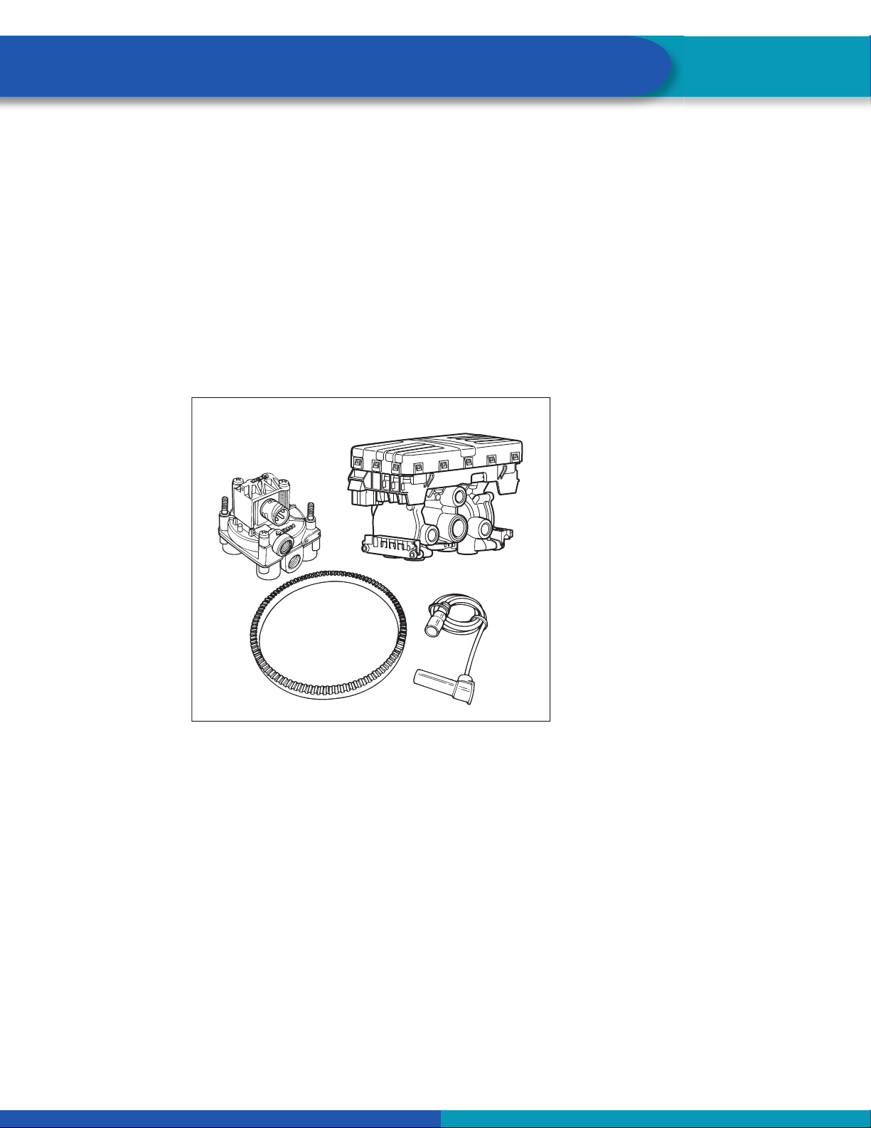
3.2 iABS Trailer ABS Parts.......................................................................................................................... 10
3.3 What Is WABCO’s iABS Trailer ABS?................................................................................................... 10
3.4 System Configuration............................................................................................................................ 10
3.5 How Trailer ABS Works......................................................................................................................... 11
3.6 System Components............................................................................................................................. 11
4 ABS Questions and Answers........................................................................................................................ 15
4.1 The ECU ............................................................................................................................................... 15
4.2 Power Line Carrier (PLC)...................................................................................................................... 15
4.3 ABS Indicator Lamps ............................................................................................................................ 16
4.4 Types of Faults...................................................................................................................................... 18
4.5 Frequently Asked Questions ................................................................................................................. 19
5 System Configurations.................................................................................................................................. 20
5.1 iABS Installation Diagrams ................................................................................................................... 20
5.2 Power Cable Wiring Diagrams.............................................................................................................. 29
6 Diagnostics..................................................................................................................................................... 30
6.1 Important PLC Information for Blink Code Diagnostics......................................................................... 30
6.2 TOOLBOX PLUS™ SOFTWARE ......................................................................................................... 31
6.3 Initial Power-up Check .......................................................................................................................... 37
6.4 Power and Ground Checks .................................................................................................................. 37
6.5 Blink Code Diagnostics ......................................................................................................................... 38
7 Component Replacement............................................................................................................................ 115
7.1 Wheel Speed Sensor .......................................................................................................................... 116
7.2 ABS Relay Valve (Figure 7.3) ............................................................................................................. 117
7.3 ECU/Valve Assembly .......................................................................................................................... 118

3
Table of Contents
T
able of Contents
8 Sensor Adjustment and Component Testing ............................................................................................ 123
8.1 How to Test Wheel Speed Sensors .................................................................................................... 123
8.2 Check ABS Functions ......................................................................................................................... 124
8.3 ABS External Modulator Valve............................................................................................................ 124
8.4 End of Line Testing ............................................................................................................................. 124
8.5 End of Line Testing without TOOLBOX PLUS™ Software.................................................................. 132
8.6 Inspect the Sensor and Air Line Installation (2S/2M Standard) .......................................................... 133
8.7 Trailer Identification............................................................................................................................. 138
9 Troubleshooting ........................................................................................................................................... 139
9.1 Automatic Lift Axle Troubleshooting ................................................................................................... 139
9.2 Tag Axle Troubleshooting.................................................................................................................... 152
9.3 Axle Load Monitoring Troubleshooting................................................................................................ 159
9.4 Tire Inflation Communication System Troubleshooting....................................................................... 163
9.5 Door Ajar System Troubleshooting ..................................................................................................... 168
9.6 Integrated Speed Switch System........................................................................................................ 172
10 Appendix I..................................................................................................................................................... 175
10.1 TraiIer ABS Indicator Lamp on Vehicle Dash ...................................................................................... 175
11 Appendix II.................................................................................................................................................... 177
11.1 Installing Sensors on Non-ABS-Prepped Axles .................................................................................. 177
12 Appendix III................................................................................................................................................... 179
12.1 Cable Routing Guidelines ................................................................................................................... 179
12.2 Cable Strain Relief Guidelines ............................................................................................................ 180
13 Appendix IV .................................................................................................................................................. 184
13.1 Vehicle Electrical Grounding Guidelines ............................................................................................. 184
14 Appendix V .................................................................................................................................................. 185
14.1 Parts and Variant List.......................................................................................................................... 185
Edition 1
Version 1 (05.2020)
MM19001 (en)
This publication is not subject to any update service. Information contained in this
publication was in effect at the time the publication was approved for printing and is
subject to change without notice or liability. WABCO reserves the right to revise the
information presented or to discontinue the production of parts described at any time.

4
General Information
1 General Information
Symbols used in this document
DANGER
Description of an immediate situation which will result in irreversible injury or death if the warning is
ignored.
WARNING
Description of a possible situation which may result in irreversible injury or death if the warning is
ignored.
CAUTION
Description of a possible situation which may result in irreversible injury if the warning is ignored.
NOTICE
Description of a possible situation which may result in material damage if the warning is ignored.
Important information, notes and/or tips
Reference to information on the internet
1. Action step
- Action step
Consequence of an action
List
•List
Note on the use of a tool/WABCO tool
How to Obtain Additional Maintenance, Service and Product Information
If you have any questions about the material covered in this publication, or for more information about
the WABCO product line, please contact WABCO Customer Care Center at 855-228-3203, by email at

5
General Information
How to Obtain Additional Maintenance, Service and Product Information
If you have any questions about the material covered in this publication, or for more information about
the WABCO product line, please contact WABCO Customer Care Center at 855-228-3203, by email at
Refer to the Society of Automotive Engineers (SAE) website to find all current SAE documents and
standards applicable to WABCO products (such as SAE J447 and SAE J908 at www.sae.org).
Refer to the National Highway Traffic Safety Administration (NHTSA) website to find all current documents
referenced in the manual at www.nhtsa.gov.
WABCO TOOLBOX PLUS™Software
The TOOLBOX PLUS™ Software provides PC diagnostics for WABCO products and can be purchased
and downloaded from https://wabco.snapon.com. For complete instructions for using TOOLBOX™
Software version 12, refer to the TOOLBOX™ Quick Start Guide TP99102. For TOOLBOX PLUS™ refer to
User's Guide MM19047. To obtain this literature, visit www.wabco-na.com/literature.
WABCO Academy
https://www.wabco-academy.com/home/
WABCO Online product catalog
http://www.wabco-customercenter.com/
Your direct contact to WABCO
WABCO North America LLC
WABCO USA LLC
1220 Pacific Drive
Auburn Hills, MI 48326
Customer Care Center: (855) 228-3203
www.wabco-na.com

6
Safety Information
2 Safety Information
Provisions for a safe work environment
Only trained and qualified automotive technicians and auto mechanics may carry out work on the
vehicle.
Read this publication carefully.
Follow all warnings, notices and instructions to avoid personal injury and property damage.
Always abide by the vehicle and trailer manufacturer’s specifications and instructions.
Observe all accident regulations of the respective company as well as regional and national regulations.
The workplace should be dry, sufficiently lit and ventilated.
Use personal protective equipment if required (safety shoes, protective goggles, respiratory protection
and ear protectors).
Read and observe all Danger, Warning and Caution hazard alert messages in this publication. They provide
information that can help prevent serious personal injury, damage to components, or both.
WARNING
To prevent serious eye injury, always wear safe eye protection when you perform vehicle maintenance or
service.
WARNING
Park the vehicle on a level surface. Block the wheels to prevent the vehicle from moving. Support the
vehicle with safety stands. Do not work under a vehicle supported only by jacks. Jacks can slip or fall
over. Serious personal injury and damage to components can result.
WARNING
It is also recommended to disable or lower any lift axle or tag axle system on the trailer before working
on it. Otherwise, the user has to be aware of possible sudden motion of trailer vehicle body that can lead
to injuries.
CAUTION
Unintended voltages induced into the ECU can damage the electronic control unit (ECU). Disconnect
all connectors from the ECU before you perform any welding, electrostatic painting, or any other activity
that applies high voltage to the vehicle frame. Refer to the equipment manufacturer‘s recommended
instructions for correct procedures.
This manual contains maintenance procedures for WABCO’s iABS™Trailer ABS system with PLC and
CAN. Before you begin procedures:
1. Read and understand all instructions and procedures before you begin to service components.
2. Read and observe all Caution and Warning safety alerts that precede instructions or procedures you
will perform. These alerts help to avoid damage to components, serious personal injury, or both.
3. Follow your company’s maintenance and service, installation, and diagnostics guidelines.
4. Use special tools when required to help avoid serious personal injury and damage to components.

7
Safety Information
2.1 Trailer Grounding and Protection from Electrostatic Discharge
2.1.1 Note During Servicing the Trailer
Prevent potential resistance differences in grounding between components (such as axles) and the vehicle
frame (chassis).
Make sure that the resistance between metallic parts of the components connected to the trailer frame is
less than 10 Ohm (< 10 ).
Connect moving or insulated vehicle parts (such as axles) in a electrically conductive manner with the
frame.
Ensure a secure and adequate chassis ground at the J560 seven way connector ground pin on the trailer.
Use electrically conductive bolted connections when fastening the ECUs to the trailer frame.
2.1.2 Welding Work on the Trailer
Disconnect power to the trailer.
Disconnect all cable connections to devices and components and protect the plug-ins and connections from
contamination and humidity.
Always connect the grounding electrode directly with the metal next to the welding position when welding,
to prevent magnetic fields and current flow via the cable or components.
Make sure that grounding connections are robust by removing paint or rust at the connection points.
Prevent heat influences from the welding activity on devices and cabling when welding.
2.1.3 Note During Electrostatic Painting the Trailer Frame or Bogie
Disconnect all cable connections to devices and components and protect the plug-ins and connections from
contamination and humidity.
2.2 Vehicle Electrical Grounding Guidelines
Consult your trailer manufacturer (OEM) for further instructions on how to perform this task. This ensures
that the trailer OE warranty is not voided.
Ensure that the vehicle includes a correct common chassis ground point. A common chassis ground point
connects the trailer frame/chassis to the ground pin of the J560 seven-way connector and will protect the
vehicle electrical system from unwanted electrical noise.
Common chassis ground can be verified by measuring the resistance between the J560 ground pin and the
vehicle chassis (or frame) and confirming that the resistance is less than 10 ohm (< 10 ). If this is not the
case, the electrical contact at the common chassis ground point is not sufficient or not present. If a common
chassis ground point is present, but not sufficient, ensure that there is no paint or debris inhibiting electrical
contact at the ground point. If a common chassis ground point is not present, WABCO requires adding one.
Do not add more than one common chassis ground point (connecting the J560 ground pin to
the chassis) to avoid potential ground shifts within the vehicle electrical system. This could
potentially cause damage to the ABS ECU and other electric components on the trailer.

8
Safety Information
Additionally, all standard trailer components, such as axles, should also be electrically connected to the
common chassis ground. If the axles are not correctly grounded to the chassis, a ground strap electrically
connecting the axle to the chassis must be added to ensure adequate protection from unwanted electrical
noise. This can be verified by measuring the maximum resistance between the vehicle chassis/frame and
the other trailer component, then confirming that the resistance is less than 10 ohm (< 10 ).
For more details concerning correct vehicle grounding, reference SAE standard J1908.

9
Introduction
3 Introduction
This manual contains service and diagnostic information for WABCO iABS Trailer ABS system with Power
Line Carrier (PLC) and CAN capability.
3.1 Identifying iABS
To identify the iABS system, check the identification tag on the Electronic Control Unit (ECU). Figure 3.1.
The part numbers for iABS systems are:
400 500 320 0 (2S/1M Standard)
400 500 420 0 (2S/2M, 4S/2M Standard)
400 500 425 0 (4S/2M Standard for Pull Trailers)
400 500 430 0 (2S/2M, 4S/2M and 4S/3M Premium)
400 500 350 0 (2S/1M Premium)
Fig. 3.1
Cntry of Origin
Last Two Digits=Build Year
4017190a
WABCO ID No.
Data Coding
PRI
Optional
0701
400 500 102 0
Date of Manufacture Code
First Two Digits=Build Week
If you are not able to identify the version and need to request service literature, please visit
wabco-na.com. Otherwise, contact WABCO Customer Care at 855-228-3203.
This manual covers servicing and repair information for a trailer already equipped with an iABS valve
assembly. If performing a new installation, refer to the following documents:
iABS 2S/1M Install Guide: TP18007
iABS 2S/2M, 4S/2M and 4S/3M Install Guide: TP18006

10
Introduction
3.2 iABS Trailer ABS Parts
Parts book PB-8857AS lists WABCO iABS replacement parts. To obtain a copy, go to wabco-auto.com.
For warranty information refer to SP-1375 which can be found at www.wabco-auto.com. For further
information, contact the WABCO Customer Care Center at 855-228-3203.
3.3 What Is WABCO’s iABS Trailer ABS?
WABCO’s iABS Trailer ABS is an electronic, self-monitoring system that works with standard air brakes. In
addition, iABS includes Power Line Carrier (PLC) capability and CAN capability. PLC information is included
in the ABS Q & A Section of this manual. The major components of the system are the Electronic Control
Unit (ECU)/Valve Assembly, External ABS Modulator Valve (for 3M systems), tooth wheel and wheel
speed sensor. Figure 3.2.
Fig. 3.2
4015787a
EXTERNAL ABS
MODULATOR VALVE
(FOR 3M
CONFIGURATIONS)
ECU/VALVE
ASSEMBLY
WHEEL SPEED
SENSOR
TOOTH
WHEEL
3.4 System Configuration
The ABS configuration defines the number of wheel speed sensors and ABS modulator valves used in a
system. For example, a 2S/1M configuration includes two wheel sensors and one ABS modulator valve.
A 2S/2M configuration includes two wheel sensors and two ABS modulator valves. A 4S/2M configuration
includes four wheel sensors and two ABS modulator valves.
There is a specific ECU/valve assembly for each configuration:
For 2S/1M Standard, the assembly consists of an ECU and a single modulator valve assembly
For 2S/2M Standard and 4S/2M, the assembly consists of an ECU and a dual modulator valve
assembly (one valve that combines the function of two modulator valves).
A 4S/3M premium configuration consists of an ECU/dual modulator valve assembly and one external
ABS modulator valve.

11
Introduction
3.5 How Trailer ABS Works
WABCO ABS is an electronic system that monitors and controls wheel speed during braking. The system
works with standard air brake systems.
ABS monitors wheel speeds at all times and controls braking during wheel lock situations. The system
improves vehicle stability and control by reducing wheel lock during braking.
The ECU receives and processes signals from the wheel speed sensors. When the ECU detects a wheel
lockup, the unit activates the appropriate modulator valve, and the air pressure is controlled to the wheel
ends.
In the event of a malfunction in the system, the ABS in the affected wheel(s) is disabled; that wheel still has
normal brakes. The other wheels keep the ABS function.
Two ABS indicator lamps (one on the dash of the tractor and one on the side of the trailer) let drivers know
the status of the system.
3.6 System Components
3.6.1 ECU/Valve Assembly (Figure 3.3)
12 volt for Standard and 8-32 volt for Premium units.
Integrated ECU and ABS relay valve.
•ECU and valve assembly are serviceable items.
The ECU/Valve Assembly may be mounted with the control port facing either the front or rear of the
trailer.
Fig. 3.3 2S/2M, 4S/2M STANDARD
2S/2M, 4S/2M AND
4S/3M PREMIUM
2S/1M STANDARD
4015795b
3.6.2 ABS External Modulator Valve (Figure 3.4)
Controls air pressure to the brake chambers where it is plumbed.
During ABS operation, the valve adjusts air pressure to the brake chambers to control braking and
prevent wheel lock.
Used in conjunction with ECU/Valve Assembly for 3M systems.

12
Introduction
3.6.3 Sensor with Molded Socket (Figure 3.5)
Measures the speed of a tooth wheel rotating with the vehicle wheel.
Produces an output voltage proportional to wheel speed.
3.6.4 Sensor Clip (Figure 3.6)
Holds the wheel speed sensor in close proximity to the tooth wheel.
3.6.5 Tooth Wheel (Figure 3.7)
A machined ring mounted to the machined surface on the hub of each ABS-monitored wheel.
Fig. 3.4
1002073c
Fig. 3.5
1002074a
Fig. 3.6
1002075a
Fig. 3.7
1002085a

13
Introduction
3.6.6 Cables for iABS (Figure 3.8)
Fig. 3.8
4015788b
POWER CABLE WITH
WEATHERPACK CONNECTION
ABS SENSOR EXTENSION CABLE
3.6.7 iABS Trailer ABS Indicator
Provides information about the operation of the ABS indicator lamp.
Label is self-adhesive and is mounted on the trailer near the ABS indicator lamp.
If there is no warning label on your trailer, let your supervisor know. Labels are available from WABCO.
Ask for Part Number TP95172.
3.6.8 TOOLBOX PLUS™ Software (Figure 3.9)
TOOLBOX PLUS™ Software is a PC-based diagnostics program that can display fault codes, wheel speed
data, test individual components, verify installation wiring and is required to perform a sign-off for the iABS
system.
WABCO TOOLBOX PLUS™ Software supports the iABS system. TOOLBOX PLUS™ Software is
available for purchase via download at the wabco.snapon.com website.
Fig. 3.9
4017189a

14
Introduction
3.6.9 Noregon DLA + PLC Adapter (Figure 3.10)
Simulates the trailer ABS lamp, ensuring that the tractor is capable of “lighting the light.”
Use as a trailer/tractor tester to ensure that PLC is functioning correctly.
Currently replaced by the heavy duty trailer diagnostic adapter.
Fig. 3.10
4017175a
Available from Noregon, not provided by WABCO.
3.6.10 Noregon Heavy Duty Trailer Diagnostic Adapter (Figure 3.11)
Simulates the trailer ABS lamp, ensuring that the tractor is capable of “lighting the light.”
Use as a trailer only tester to ensure that PLC is functioning correctly.
Fig. 3.11
4017176a
Available from Noregon, not provided by WABCO.

15
ABS Questions and Answers
4 ABS Questions and Answers
This section contains ABS questions and answers.
4.1 The ECU
How do you activate the ECU?
In a constant-powered system, the ECU activates and then begins a self-diagnostic check of the system
when you turn the ignition ON. In a stoplight-powered system, the ECU activates when you apply the
brakes. All trailers manufactured on or after March 1, 1998 are equipped with ABS that has constant power
capability with stoplight power as back-up.
How does the ECU respond to a wheel approaching lock-up?
The ECU directs the ABS relay valve to function as a modulator valve and adjust air pressure to the
chambers up to five times a second. This pressure adjustment allows a wheel (or wheels) to rotate without
locking.
4.2 Power Line Carrier (PLC)
What is PLC communications?
PLC stands for Power Line Carrier, which is a method used to communicate information by multiplexing
data on the same wire used for the ABS electrical power. PLC communications convert signal message
data to a radio frequency (RF) signal on top of the +12V power line providing electrical power to the trailer.
What is multiplexing?
Multiplexing means communicating multiple signals or messages on the same transmission media. This
provides an efficient and cost effective means by decreasing the number of wires and connectors which
otherwise would be needed. Without multiplexing, it could take several wires and connections in order to
transmit several different signals to various locations on a vehicle, but with multiplexing these wires and
connectors can be significantly reduced.
Why add PLC technology to tractor and trailer ABS?
By adding PLC technology to the tractor and trailer ABS the industry is able to have the most cost effective
means to meet the March 1, 2001 FMVSS-121 in-cab trailer indicator lamp mandate with no additional
external hardware, harnesses or connectors. Additionally, this capability of communicating other information
between tractor and trailers provides many more opportunities to further improve productivity and safety.
How does it work?
The trailer ABS with PLC takes message information to be sent to the tractor and converts it to an RF
signal. The signal is then sent over the trailer ABS power line (blue wire) and the tractor ABS with PLC
receives the signal. Messages can also be sent from the tractor to the trailer via PLC.
What if a tractor is equipped with PLC technology and the trailer is not, or viceversa? Can you drive
the combination safely in that situation?
Absolutely. If the tractor is equipped with PLC and the trailer is not, or vice-versa, your ABS in-cab trailer
indicator lamp will not illuminate, but your ABS will continue to function as normal. To ensure that the trailer
ABS is functioning correctly, the trailer ABS indicator lamp mounted on the trailer should be utilized.

16
ABS Questions and Answers
What if a tractor has one manufacturer’s ABS with PLC and the trailer has another manufacturer’s
ABS with PLC? Will the two systems be compatible and operate the trailer ABS lamp as expected?
Yes. ABS with PLC from different manufacturers are designed to be compatible by controlling the trailer
ABS lamp according to the FMVSS-121 standard, even when systems from different manufacturers are
connected to each other. However, certain features beyond the control of the trailer ABS indicator lamp may
or may not be supported by all devices communicating via PLC. SAE task forces continue to standardize
common messages so that maximum compatibility may exist in the future.
How do I diagnose PLC?
PLC can be diagnosed anywhere you can connect to the main power wire on the trailer, typically tools are
designed to be plugged into the J560 connection at the nose of the trailer.
Can I use blink code diagnostics on iABS to diagnose PLC?
Yes. Section 5 of this manual describes the method of performing a blink code check using Constant Power
(ignition activation). Blink Code 17 indicates a PLC failure.
If PLC does not seem to be operating correctly, but I don’t get a Blink Code 17 when I run a blink
code check, what else could be wrong?
If there is no Blink Code 17, the ECU is functioning correctly and does not need to be replaced; however,
there could be a problem in the trailer’s wiring harness. Check the wiring system and make the necessary
repairs. If the problem persists, contact the WABCO Customer Care Center at 855-228-3203.
4.3 ABS Indicator Lamps
When replacing the bulb, to ensure correct lamp operation use an incandescent type DOT-
approved lamp, or a LED with integral load resistor.
4.3.1 ABS Indicator Lamp (on Dash)
With iABS, there are two ABS indicator lamps; one on the vehicle dash and one on the side of the trailer.
Refer to Appendix I for information about the operation of this lamp.
4.3.2 ABS Indicator Lamp (on Trailer)
What is the function of the ABS indicator lamp?
The indicator lamp enables a driver to monitor the ABS at all times. Refer to the DOT requirements for the
mounting location of the indicator lamp.
How does the indicator lamp operate?
How the indicator lamp operates depends on whether the ABS is powered by stoplight or constant power:
If the trailer was manufactured prior to February 28, 1998, or was manufactured outside of the United
States, the ABS may be either stoplight or constant powered.
If the trailer was manufactured March 1, 1998 or later — and was manufactured in the United States
— it will have constant power capability. This is mandated by Federal Motor Vehicle Safety Standard
(FMVSS) 121.
Check your trailer specification sheet to determine the type of ABS power. Table B in this section illustrate
indicator lamp operation on stoplight and constant powered ABS systems.

17
ABS Questions and Answers
Most trailers manufactured prior to February 1998 require that the brakes be applied to operate the ABS
indicator lamp. If the indicator lamp stays on when the brakes are applied to a moving vehicle, service the
ABS system.
What does the trailer ABS indicator lamp mean to service personnel?
The trailer ABS indicator lamp on the side of the trailer indicates the status of the trailer ABS. If it comes ON
and stays ON when you apply the brakes to a moving vehicle, there is an ABS malfunction. It is normal for
the lamp to come ON and go OFF to perform a bulb check, but it should not stay ON when the vehicle is
moving above 4 mph. As with any safety system, it is important not to ignore this indicator. If the indicator
lamp indicates a malfunction, the vehicle can be operated to complete the trip, but it is important to have
it serviced as soon as possible using the appropriate maintenance manual to ensure correct braking
performance and that the benefits of ABS remain available to your drivers. Typical ABS indicator lamp
mounting locations are illustrated in Figure 4.1.
Fig. 4.1
1003294d
Typical ABS Indicator Lamp Mounting Location on Side of Trailer
Can you continue to operate a vehicle when the indicator lamp indicates a fault?
Yes. When a fault exists in the ABS, standard braking returns to the affected wheel, and the ABS still
controls other monitored wheels. This lets you complete the trip. You should not ignore the indicator lamp
and should have the vehicle serviced as soon as possible after the lamp comes ON and stays ON.

18
ABS Questions and Answers
TABLE A: CONSTANT POWER
System is Ignition Powered
Brakes Ignition Fault in
System Vehicle Speed Indicator Lamps (Trailer and Dash)
Released OFF N.A. N.A. OFF
ON NO Less than 4 mph ON for 3 seconds, then go OFF.
ON NO Greater than 4 mph OFF
ON YES N.A. ON
Applied
OFF NO Less than 4 mph ON for 3 seconds, then go OFF.
OFF YES N.A. ON
ON NO Less than 4 mph OFF
ON NO Greater than 4 mph OFF
ON YES N.A. ON
TABLE B: STOPLIGHT POWER
Stoplight power is designed to be for backup only for the ABS, so if the light is not functioning per
the Constant Power table, the power and ground should be checked on the system.
System Power Comes from Activating the Stoplight Circuit.
Brakes Fault in System Vehicle Speed Indicator Lamp
Released N.A. N.A. OFF
Applied NO Less than 4 mph ON for 3 seconds, then goes OFF.
Applied NO Greater than 4 mph Flashes once, then stays OFF for remainder
of the brake application.
Applied YES N.A. ON
4.4 Types of Faults
What is a fault in the system?
A fault in the system is a problem that can exist in the ABS or in the system’s components. Faults can be
either existing faults or intermittent stored faults.
What is an existing fault?
An existing fault is a problem that exists currently in the system. For example, a damaged sensor cable is
an existing fault that the ECU will detect and store into memory until you identify the cause, repair the cable
and clear the fault from the ECU.

19
ABS Questions and Answers
What is an intermittent fault?
An intermittent fault is a problem that usually occurs only under certain driving conditions. For example,
the ECU may detect a loose cable or wire or receive an erratic signal from a wheel sensor. Since
intermittent faults can be unpredictable and may only happen periodically, you can use information stored in
ECU memory to find and correct the loose cable or wire. An intermittent fault cannot be retrieved using blink
codes.
Is an intermittent fault difficult to locate and repair?
It can be, because you may not be able to easily find the cause of the problem. WABCO recommends that
you write down intermittent faults to help you isolate a fault that recurs over a period of time.
Can the ECU store more than one fault in memory?
Yes. The ECU retains existing and intermittent faults in memory even when you turn OFF the power to the
ECU.
What if the ECU finds a fault in an ABS component during normal operation?
If the ECU senses a fault in the system (with an ABS valve, for example), the ECU turns the trailer ABS
indicator lamp on and returns the wheel controlled by that valve to standard braking. Or, if the ECU finds
a fault with one wheel speed sensor in a system that has four sensors on a tandem axle, the ECU uses
information from the other sensor on the same side of the tandem to ensure continuous ABS function. The
ECU continues to provide full ABS function to the wheels unaffected by system faults. However, the ECU
will turn the trailer ABS indicator lamp on to tell the driver a fault has been detected in the system.
4.5 Frequently Asked Questions
What is the crack pressure of the ABS valve?
The pressure at which the ABS valve opens to allow air pressure to the wheel ends is 3 to 5 psi on the
signal port of the valve.
What can cause the trailer to bounce up and down when the service brakes are applied?
It is possible the ABS is getting signal from the sensor and tone ring that it is going into an ABS event. If
the issue is more noticeable when the trailer is unloaded, it is possible the trailer has worn suspension
components that can cause the ABS to react and go into an ABS event. Review with the trailer suspension
manufacturer.
Why are my brake lights on dimly any time the trailer is powered up?
If the trailer is equipped with LED brake lights and there is no resistor in the circuit, you will get unwanted
illumination of the lights all the time. The 12v LED or circuit must have a resistor installed to prevent them
from illuminating all the time.

20
System Configurations
5 System Configurations
5.1 iABS Installation Diagrams
With iABS, the 2S/1M, 2S/2M, 4S/2M and 4S/3M sensor location designations will change depending on
how the ECU/dual modulator valve assembly is mounted. It may be mounted facing either the front or
the rear of the trailer. It is important that you identify the location of these sensors before beginning any
diagnostics. Sensor locations for both front and rear-facing installations are depicted in Figures 5.1 through
5.8.
Sensor locations for the 2S/1M Standard will not change.
Configuration Figure
2S/1M Standard Figure 5.1
2S/2M Standard Mounted with Control Port Facing Front of Trailer Figure 5.2
2S/2M Standard Mounted with Control Port Facing Rear of Trailer Figure 5.3
2S/2M Standard Mounted with Control Port Facing Front of Trailer
Figure 5.4
2S/2M Standard Mounted with Control Port Facing Rear of Trailer
4S/2M Standard Mounted with Control Port Facing Front of Trailer
Figure 5.5
4S/2M Standard Mounted with Control Port Facing Rear of Trailer
4S/2M Standard - Typical Tri-Axle - Mounted with Control Port Facing Front of Trailer
Figure 5.6
4S/2M Standard - Typical Tri-Axle - Mounted with Control Port Facing Rear of Trailer
4S/2M Standard - Typical Axle Control Installation - Mounted with Control Port Facing
Front of Trailer Figure 5.7
4S/2M Standard - Typical Axle Control Installation - Mounted with Control Port Facing
Rear of Trailer
4S/3M Premium - Typical Tri-Axle with Front Lift - Mounted with Control Port Facing
Front of Trailer Figure 5.8
4S/3M Premium - Typical Tri-Axle with Front Lift - Mounted with Control Port Facing
Rear of Trailer
This manual suits for next models
12
Table of contents
Other WABCO Automobile Accessories manuals
Popular Automobile Accessories manuals by other brands

Hirschmann
Hirschmann AUTA 4000 F 420 L installation instructions

Blueant
Blueant S4 quick start guide

Alpine
Alpine HCE-C115 owner's manual

BUSHWACKER
BUSHWACKER POCKET STYLE 20072-02 installation guide

Metra Electronics
Metra Electronics 95-7419 installation instructions

Body Armor 4x4
Body Armor 4x4 AMBUSH Series installation instructions