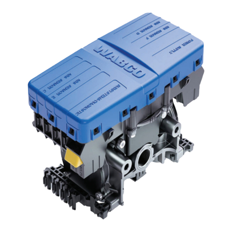
WABCO TP0735 User manual

INSTALLING TIRE INFLATION
SYSTEMS COMPATIBLE
WITH WABCO TRAILER ABS
INSTALLATION INSTRUCTIONS
TP0735


3
Table of Contents
Table of Contents
1 General Information. ...................................................................................................................................................5
1.1 Symbols Used in this Document ........................................................................................................................5
1.2 How to Obtain Additional Maintenance, Service and Product Information.........................................................6
1.3 How to Obtain Parts and Kits.............................................................................................................................6
1.4 WABCO TOOLBOX PLUS™ Software ..............................................................................................................6
1.5 WABCO Academy..............................................................................................................................................6
1.6 WABCO Online Product Catalog .......................................................................................................................6
1.7 Your Direct Contact to ZF CVS ..........................................................................................................................7
2 Safety Information.......................................................................................................................................................8
2.1 Provisions for a safe work environment .............................................................................................................8
3 Introduction. ................................................................................................................................................................9
4 Installation. ................................................................................................................................................................10
4.1 InstallationofMeritorTireInationSystem ......................................................................................................10
4.2 InstallationofCompatibleTireInationSystems(HendricksonTiremaaxTireInationSystem
andSTEMCOAerisTireInationSystem).......................................................................................................13
4.3 ActivatingtheTireInationSystemwithTOOLBOX™Software .....................................................................15
5 TireInationCommunicationSystemTroubleshooting. ......................................................................................17
6 Appendix I..................................................................................................................................................................19
6.1 InstallingSensorsonNon-ABS-PreppedAxles ...............................................................................................19
7 Appendix II.................................................................................................................................................................21
7.1 Cable Strain Relief Guidelines .........................................................................................................................21
8 Appendix III................................................................................................................................................................26
8.1 Vehicle Electrical Grounding Guidelines..........................................................................................................26

Edition 1
Version 2 (03.2022)
TP0735 (en)
This publication is not subject to any update service. Information contained in this
publication was in effect at the time the publication was approved for printing and is
subject to change without notice or liability. ZF CV Systems North America LLC reserves
the right to revise the information presented or to discontinue the production of parts
described at any time.
Youwillndthecurrenteditionat:https://zf.com/cvliterature

1 General Information
1.1 SymbolsUsedinthisDocument
DANGER
Description of an immediate situation which will result in irreversible injury or death if the warning is
ignored.
WARNING
Description of a possible situation which may result in irreversible injury or death if the warning is
ignored.
CAUTION
Description of a possible situation which may result in irreversible injury if the warning is ignored.
NOTICE
Description of a possible situation which may result in material damage if the warning is ignored.
Importantinformation,noticesand/ortips
Reference to information on the Internet
Descriptivetext
– Action step
1. Actionstep1(inascendingorder)
2. Actionstep2(inascendingorder)
ÖResult of an action
• Listing
Indicatingtheuseofatool/WABCOtool
5
General Information

6
General Information
1.2 How to Obtain Additional Maintenance, Service and Product
Information
If you have any questions about the material covered in this publication, or for more
information about the WABCO product line, please contact WABCO Customer Care
Centerat855-228-3203,byemailat[email protected],orvisitourwebsite:
www.zf.com/cv.
Refer to the Society of Automotive Engineers (SAE) website to nd all current SAE
documentsandstandardsapplicabletoWABCOproducts(suchasSAEJ447andSAE
J908atwww.sae.org).
Referto theNationalHighwayTrafcSafetyAdministration(NHTSA) websitetond all
current documents referenced in the manual at www.nhtsa.gov.
1.3 How to Obtain Parts and Kits
ContacttheWABCOCustomerCareCenterat855-228-3203(UnitedStatesandCanada);
800-953-0248(Mexico).Email:[email protected].
1.4 WABCO TOOLBOX PLUS™ Software
TOOLBOX PLUS™ Software provides PC diagnostic for WABCO products and can be
purchasedanddownloadedfromhttps://wabco.snapon.com.
The software User Guide, MM19047 can be obtained by visiting our Literature Center.
Purchase and Download TOOLBOX PLUS™
https://wabco.snapon.com
ZF Commercial Vehicle Literature Center
https://zf.com/cvliterature
1.5 WABCO Academy
www.wabco-academy.com
1.6 WABCOOnlineProductCatalog
www.wabco-customercenter.com

7
General Information
1.7 YourDirectContacttoZFCVS
ZFCVSystemsNorthAmericaLLC
1220PacicDrive
Auburn Hills, MI 48326
CustomerCareCenter:(855)228-3203
www.zf.com/cv

8
Safety Information
2 Safety Information
2.1 Provisions for a safe work environment
Onlyexperienced,trainedandqualiedautomotivetechniciansmaycarryoutworkonthevehicle.
Read this publication carefully.
Follow all warnings, notices and instructions to avoid personal injury and property damage.
Alwaysabidebythevehicle’sOriginalEquipmentManufacturer(OEM)specicationsandinstructions.
Observe all accident regulations of the repair facility as well as regional and national regulations.
Theworkplaceshouldbedry,sufcientlylitandventilated.
Usepersonalprotectiveequipmentifrequired(safetyshoes,protectivegoggles,respiratoryprotection
andearprotectors).
ReadandobserveallDanger,WarningandCautionhazardalertmessagesinthispublication.Theyprovide
information that can help prevent serious personal injury, damage to components, or both.
WARNING
To prevent serious eye injury, always wear safe eye protection when you perform vehicle
maintenance or service.
WARNING
Park the vehicle on a level surface. Block the wheels to prevent the vehicle from moving. Support
thevehiclewithsafetystands.Donotworkunderavehiclesupportedonlybyjacks.Jackscanslip
or fall over. Serious personal injury and damage to components can result.
WARNING
ThisproductcanexposeyoutochemicalsincludingNickel,whichisknowntotheStateofCalifornia
to cause cancer and birth defects or other reproductive harm. For more information, go to
www.P65Warnings.ca.gov.
WARNING
Whenyouworkonanelectricalsystem,thepossibilityofelectricalshockexists,andsparkscan
igniteammablesubstances.Youmustalwaysdisconnectthebatterygroundcablebeforeyouwork
on an electrical system to prevent serious personal injury and damage to components.

9
Introduction
3 Introduction
Tireinationsystemsusecompressedairfromthetrailertoinateanytrailertirethatfallsbelowthetireair
pressuresettingduringoperation.Airfromtheexistingtrailerairsupplyisroutedtoacontrolbox,theninto
eachaxle.
Actingasaconduit,axlescarryairthrougharotaryunionassemblyatthespindleendwhichthen
distributes air to each tire as needed.
Thistechnicalbulletincoversinstallationofthepartsnecessaryfortrailerstohavetireinationsystem
communication.
Anindicatorlightonthefrontofthetrailerinformsthedriverofanexcessiveamountofairow
through the system. If the indicator light is illuminated, appropriate maintenance or repairs to
the system should be performed.

10
Installation
4 Installation
4.1 InstallationofMeritorTireInationSystem
1. Wear safe eye protection.
2. Park the vehicle on a level surface. Block the wheels to prevent the vehicle from moving.
3. Raisethevehiclesothatthewheelstobeservicedareofftheground.Supporttheaxletobeserviced
with safety stands.
4. InstalltheMTIScontrolboxwiththeWABCOMTISpigtailcable(partnumberxxxxxxxxMW).The“MW”
attheendoftheMTISpartnumbersigniesthepigtailcableispre-installedintothecontrolbox.
Figure 1.
Fig. 1
SENSOR
EXTENSION CABLE
P/N 449 712 XXX 0
4006454d
2S/1M BASIC
P/N 400 500 106 0
2S/2M TO 4S/3M
PREMIUM
P/N 400 500 105 0
PRE-INSTALLED
WABCO MTIS
PIGTAIL CABLE
GENERIC I/O
CABLE
P/N 449 324 XXX 0
MTIS
ELECTRICAL CABLE
UNUSED
BLACK
LOCKNUT

11
Installation
5. Insert the black and white wires of the MTIS electrical cable through the unused black locknut and into
theMTISbox.Figure2.TurntheblacklocknutCLOCKWISEtofastensecurely.
Fig. 2
4006529c
12-VOLT RETURN
(BLACK WIRES)
12V
(WHITE
WIRE)
FLOW
SENSING
SWITCH
PETCOCK
DUAL MALE
TAB (BLACK
WIRE)
WABCO PIGTAIL
WIRE
Bothblackwiresmustbeconnectedtoonesideoftheowswitch(sidewiththedualmaletab)
andthewhitewiremustbeconnectedtotheoppositesideoftheowswitch.
6. Fastenthe12-volt(white)wireoftheMTISelectricalcableterminalontothetabontheoppositeside
(bottomshown)oftheowsensingswitch.Conrmthatthe+12-voltreturn(black)wireterminalofthe
WABCOMTISpigtailcableisattachedtotheowsensingswitchasshowninFigure2.
7. Fastenthe12-volt(white)wireoftheMTISelectricalcableterminalontothetabontheoppositeside
(bottomshown)oftheowsensingswitch.Figure2.
Refer to Figure 3 for more detailed assembly, installation, inspection and maintenance
information for MTIS.

12
Installation
Fig. 3
4009668a
MTIS WARNING
LIGHT
BATTERY
RETURN
GROUND
MTIS CONTROL BOX
FLOW
SWITCH
PIGTAIL
W/DIODE
12 VDC FROM
J560 CONNECTOR
CONNECTED
TO POWER
CABLE D1
MTIS STATUS DETECTION BY MW TRAILER ABS SYSTEM
8. RemovetheprotectivecapsfromtheWABCOMTISpigtailcableandthegenericinput/output(I/O)
cable.
9. ConnecttheWABCOMTISpigtailcabletothesensorextensioncable.Figure1.
10. ConnectthesensorextensioncabletothegenericI/Ocable.Figure1.
11. Secure the cable as appropriate with the correct strain relief to prevent overtightening or overstretched
condition that would damage the wire.
The MTIS indicator light must be either a load resisted LED lamp, part number 31263-20, or an
incandescent light. Refer to the Meritor part list on page 14.

13
Installation
4.2 InstallationofCompatibleTireInationSystems
(HendricksonTiremaaxTireInationSystemand
STEMCOAerisTireInationSystem)
RefertoFigure4forcorrectconnectionofthetrailerABSsystem,partnumber4005001050(4S2M)or
4005001060(2S1M),tothetireinationsystem.
Fig. 4
TRAILER ABS SYSTEM
P/N 400 500 105 0
P/N 400 500 106 0
SUPPLY/ GIO CABLE
P/N 449 324 XXX 0
4014797b
CONTROLLER
ASSEMBLY
CONNECTOR
FIVE-PIN
CONNECTOR
FIVE-PIN
POWER SUPPLY
CONNECTOR
INDICATOR
CONNECTION
TIRE INFLATION
SYSTEM
JUMPER HARNESS
TIREMAAX: P/N 449 025 XXX 0
STEMCO: P/N 449 027 XXX 0
COMPATIBLE TIRE INFLATION SYSTEMS FOR ENHANCED EASY STOP
1. Connectthesupply/GIOcable,partnumber449324XXX0,intotheECU’spowerconnectorportand
secure it with the locking tab.
2. Usingthejumperharness,eitherTIREMAAX(449025XXX0)orSTEMCO(449027XXX0),connect
thetireinationsystemtotheconnectoronthesupply/GIOcable,partnumber449324XXX0.
3. Usingthejumperharness,connecttireinationsystemtotheve-pinpowersupplyconnector.

14
Installation
WABCO Part List
DESCRIPTION LENGTH PART
NUMBER
2S/1MPremiumSystem 400 500 106 0
2S/2M-4S/3MPremiumSystem 400 500 105 0
PowerGenericI/O“Y”Cable 0.5 meter 449 324 005 0
PowerGenericI/O“Y”Cable 1.0 meter 449 324 010 0
PowerGenericI/O“Y”Cable 3.0 meters 449 324 030 0
PowerGenericI/O“Y”Cable 4.7 meters 449 324 047 0
PowerGenericI/O“Y”Cable 6.0 meters 449 324 060 0
SensorExtensionCable 0.76 meter 449 712 008 0
SensorExtensionCable 1.78 meters 449 712 018 0
SensorExtensionCable 1.90 meters 449 712 019 0
SensorExtensionCable 3.8 meters 449 712 038 0
SensorExtensionCable 5.1 meters 449 712 051 0
SensorExtensionCable 6.35 meters 449 712 064 0
SensorExtensionCable 10.0 meters 449 025 100 0
SensorExtension90° 0.8 meter 449 713 008 0
SensorExtension90° 1.8 meters 449 713 018 0
SensorExtension90° 3.0 meters 449 713 030 0
SensorExtension90° 5.0 meters 449 713 050 0
SensorExtension90° 7.0 meter 449 713 070 0
SensorExtension90° 9.0 meter 449 713 090 0
SensorExtension90° 12.0 meter 449 713 120 0
SensorExtension90° 17.0 meter 449 713 170 0
HendricksonTiremaaxJumperHarness 1.0 meter 449 025 010 0
HendricksonTiremaaxJumperHarness 2.5 meters 449 025 025 0
HendricksonTiremaaxJumperHarness 5.0 meters 449 025 050 0
StemcoAerisJumperHarness 1.0 meter 449 027 010 0
StemcoAerisJumperHarness 2.5 meters 449 027 025 0
StemcoAerisJumperHarness 5.0 meters 449 027 050 0
Meritor Part List
DESCRIPTION PART
NUMBER
LED Lamp with Resistor 31263-20 31263-20
LED Bracket 31263-21 31263-21
LED Pigtail 31263-16 31263-16
LED Kit — Includes LED lamp with
resistor, bracket, sealing grommet, label
forunderLEDtwolabels(oneforeach
sideoftherearofthetrailer)
H1263-06-MW
MTIS Cable Pigtail 31184-00 31184-00

15
Installation
4.3 ActivatingtheTireInationSystemwithTOOLBOX™Software
Oncethehardwarehasbeeninstalled,thetireinationsystemmustbeactivatedusingWABCO
TOOLBOX™Softwareversion12.4orlater.Wheninstallingtireinationsystemsoptiononnewor
replacement ECUs, the activation process is part of the normal programming procedure.
1. ClicktheTOOLBOXicononthedesktopandthenclicktheJ1708/PLCicon.Figure5.
Fig. 5
4014793a
2. Click on the Trailer ABS Diagnostics icon to initiate the ABS portion of TOOLBOX™ Software. Figure 6.
To enable trailer and TOOLBOX™ Software communication, make sure the correct adapter is
selected under Adapter Selection on TOOLBOX main screen under Utility Tab for TOOLBOX
12 or Adapter selection for TOOLBOX PLUS main screen.
Fig. 6
4014794a

16
Installation
3. Fromthetopmenubar,gototheModifypull-downmenuandselectGIOConguration.Figure7.
Fig. 7
4014795a
4. WhentheGIOCongurationscreenisdisplayed,clicktheTireInationCommunicationradialbutton.
Ensurethatacircleappearsinthebox.Then,presstheDownloadbuttonatthebottomofthescreen.
Figure 8.
Fig. 8
4014796a
5. Onceamessageisdisplayedconrmingasuccessfulsave,clickExitinthemainscreentoclosethe
TOOLBOX™ Software.
6. Cycle the power on the trailer in order to reset the ECU.

17
Tire Ination Communication System Troubleshooting
5 Tire Ination Communication System Troubleshooting
ECUs 400 500 105 0 and 400 500 106 0 are the only trailer ABS valves that have Tire Ination
Communication functionality.
The rst step taken when troubleshooting the Tire Ination Communication System is to ensure that the
system is electrically connected correctly. Refer to Figure 10.
If the Tire Ination system status lamp is not present or is not functioning, then the Tire Ination
Communication System will not function.
TIO les enable additional functionality such as tire monitoring, for the InfoLink-capable ECUs. If a TIO
needs to be replaced or removed, contact the WABCO North America Customer Care Center at
855-228-3203.
This troubleshooting section is based on the use of TOOLBOX™ Software version 12 or higher. If you have
an earlier version of TOOLBOX™ Software, visit https://wabco.snapon.com.
Fig. 9
4012497c
Condition
Experienced Action To Ta ke Tr oubleshooting Details
MTIS LED Illuminates with
a Dim Glow All the Time
Confirm the MTIS LED is an incandescent
or Meritor LED with resistor part number
31263-20.
Replace light as necessary.
Ensure light is grounded correctly.
WABCO Tire
Inflation Communication
System is not Broadcasting
a “Low Tire Pressure”
Message When There is a
Fill Event and the MTIS
Light is Illuminated
Correct installation needs to be verified.Confirm WABCO MTIS Communication System is installed per
Figures 2 and 10.
Make sure all electrical connections are fully seated.
ECU valve should audibly click during its
power-up self-test.
Ensure that 12 volts is present at pin A-3 and (Ground Pin) on the ECU
power connector.
Check continuity of the power/I/O cable.
Check diode on pre-installed MTIS cable pigtail. Place the volt/ohm meter
to “Diode”. Place red lead on single male pin. Place the black lead on the
dual tab connector. Continuity should be observed on the volt/ohm meter.
Switching the leads in the opposite direction, an “Open” should be
displayed on the volt/ohm meter. Refer to Figure 11.
Confirm part number 400 500 105 0 or
400 500 106 0 is installed.
Connect TOOLBOX™ Software 12 or higher and part number can be
viewed on the Trailer ABS main screen.
Confirm T_0109b.tio has been installed to
the ECU.
To access the Notebook section of the ECU, perform the following:
1. Select Modify on the top toolbar of the Trailer ABS TOOLBOX
application.
2. Select Notebook to confirm T_0109b.tio can be viewed in the
“Service Information” area.
3. If T_0109b.tio is not visible in the Notebook, go back to Loading TIO
Files section of this publication.
“Low Tire Pressure”
Message is Being
Broadcasted All the Time
Correct installation needs to be verified.
Make sure all electrical connections are fully seated.
Confirm the MTIS LED is an incandescent
or Meritor LED w/resistor part number
31263-20.
Replace light as necessary.
Ensure light is grounded correctly.
MTIS LED Does Not
Illuminate During a Fill
Event
Correct installation needs to be verified. Confirm MTIS system is installed per MM14P.
Confirm MTIS LED is not burned out.
Replace MTIS LED as required with Meritor part number 31263-20.
The Parameter File
T_0109b.tio Has Been
Successfully Downloaded
to the ECU, but MTIS
Message is Not Being
Broadcast
Confirm T_0109b.tio is visible in the
“Notebook” section of TOOLBOX™
Software 12 or higher.
Contact the WABCO Customer Care Center at 855-228-3203.
Check continuity for the 449 324 XXX X D1 cable from the 8-pin
connector (Pin 5) to the 2-pin sensor socket (C1). Refer to Figure 10.
Confirm WABCO MTIS communication system is installed per
illustration Figures 2 and 10.

18
Tire Ination Communication System Troubleshooting
Fig. 10
4012492a
A-4
A-3
A-2
A-1
A-8
A
A-7
A-6
A-5
C
NOT USED
NOT USED
NOT USED
B
B-D
B-A
B-B
B-E
C
C-2
C-1
A
A-1
A-2
A-3
A-4
A-5
A-6
A-7
A-8
C-2
C-1
B-A
B-B BPOWER GENERIC I/O “Y” CABLE
P/N 449 324 XXX X
B-E
B-C B-D
A
B
Fig. 11
4012493b
1 BLACK
2 NOT CONNECTED
DIODE
BLACK
1
2
WABCO TIRE INFLATION SYSTEM CABLE PIGTAIL
P/N 31184-00

19
Appendix I
6 Appendix I
6.1 InstallingSensorsonNon-ABS-PreppedAxles
Sensorlocationsvaryduetosuspensiontype.WABCOrecommendsplacingthesensorontheaxlethat
will provide the most braking performance. Contact your suspension manufacturer for further information.
1. Applyamineraloil-basedgreasethatcontainsmolydisuldetothesensorspringclip,thebodyofthe
sensor and the bore of the sensor block. The grease must be anti-corrosive and contain adhesive
propertiesthatwillcontinuouslyenduretemperaturesfrom−40°to300°F(−40°to150°C).
2. Push the spring clip into the sensor holder from the inboard side, until the spring clip tabs are against
the sensor holder. Push the sensor into the spring clip as far as possible.
UseWABCOspringclipstoensureacorrectt.
3. Push the spring clip into the sensor holder from the inboard side until the spring clip tabs are against
the sensor holder. Push the sensor into the spring clip as far as possible. Figure 12.
Fig. 12 SPRING
CLIP TAB
SENSOR
SPRING
CLIP
SENSOR
HOLDER
4003572a
4. Route the sensor cable toward the brake chamber, over the brake spider or through the pre-stamped
holededicatedtoABSsensors.Routetothebacksideoftheaxle.Securethecabletotheaxle
between the brake spider and the suspension brackets. Continue to route the sensor cable behind the
springseats.Securethecabletotheaxleoneinchfromthemoldedsensorplug.Figure13.
Do not overtighten tie wraps on a cable. Overtightening can damage the cable. Do not tie wrap
themoldedsensorplug.ThesensorextensioncablemustfollowthebrakehosetotheECU/valve
assemblytoallowforaxlejounceandrebound.
Brakehoseclipswithaprovisionforthesensorextensioncablearerecommendedasopposedtotie
wraps. WABCO does not supply this part.
Fig. 13
SENSOR
CABLE
3"
(76 MM)
4003573a

20
Appendix I
5. Install the wheel hub carefully so that the tooth wheel pushes against the sensor as the wheel bearings
are adjusted. There should be no gap between the sensor and the tooth wheel.
6. Testthesensoroutputvoltage.Useavolt/ohmmetertochecktheoutputvoltageofthesensorswhile
rotatingthewheelatapproximately1/2revolutionpersecond.Minimumoutputmustbe0.2voltAC.If
minimum output is less than 0.2 volt AC, push the sensor toward the tooth wheel. Recheck the sensor
output.
Table of contents
Other WABCO Automobile Accessories manuals

WABCO
WABCO TEBS E User manual

WABCO
WABCO OnGuard User manual

WABCO
WABCO Truck Training Model User manual

WABCO
WABCO 2S/2M User manual

WABCO
WABCO OPTIFLOW SIDEWINGS User manual

WABCO
WABCO OnGuard User manual

WABCO
WABCO TP19108 User manual

WABCO
WABCO TP19039 User manual

WABCO
WABCO OnSide MM16167 User manual

WABCO
WABCO TP2205 User manual
Popular Automobile Accessories manuals by other brands

Steren
Steren AUT-510 user manual

Skoda
Skoda FABIA II TMB PS 035 Mounting and user instructions

Kolpin Outdoors
Kolpin Outdoors 2738 Product instructions

Black Horse Off Road
Black Horse Off Road 17G80330MSS installation instructions

banks
banks Backup Camera owner's manual

Caltrend
Caltrend TY252 installation instructions