WABCO TP19039 User manual
INSTALLING AND CONFIGURING THE
WABCO iABS WITH AUTOMATIC LIFT
AXLE CONTROL OPTION
KITS 400 612 039 0, 400 612 040 0, 400 612 041 0. MUST BE USED WITH THE WABCO
PREMIUM ECU/VALVE ASSEMBLIES: 400 500 350 0 (2S/1M), 400 500 450 0 (4S/2M)
TP19039
TECHNICAL BULLETIN


3
Table of Contents
Edition 1
Version 1 (08.2020)
TP19039 (en)
This publication is not subject to any update service. Information contained in this
publication was in effect at the time the publication was approved for printing and is subject
to change without notice or liability. WABCO reserves the right to revise the information
presented or to discontinue the production of parts described at any time.
Table of Contents
1 General Information ......................................................................................................................................... 4
2 Safety Information............................................................................................................................................ 6
3 Important Information...................................................................................................................................... 6
4 Introduction ...................................................................................................................................................... 7
4.1 Configuration of Lift Axles by Functionality ............................................................................................. 7
4.2 Installation............................................................................................................................................... 8
4.3 Automatic Lift Axle Activation Procedure .............................................................................................. 14
4.4 Lift Axle Operation Check ..................................................................................................................... 20
5 Appendix I....................................................................................................................................................... 23
5.1 Installing Sensors on Non-ABS-Prepped Axles .................................................................................... 23
6 Appendix II...................................................................................................................................................... 25
6.1 Cable Strain Relief Guidelines .............................................................................................................. 25
7 Appendix III..................................................................................................................................................... 28
7.1 Vehicle Electrical Grounding Guidelines ............................................................................................... 28
8 Appendix IV ................................................................................................................................................... 29
8.1 Parts and Variant List............................................................................................................................ 29
4
General Information
1 General Information
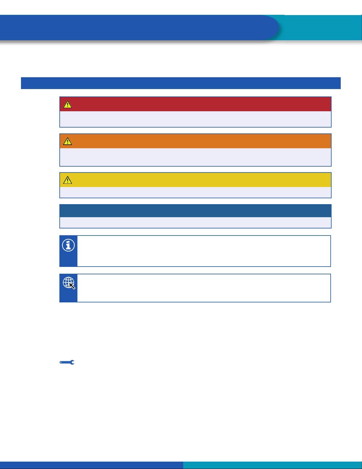
Symbols used in this document
DANGER
Description of an immediate situation which will result in irreversible injury or death if the warning is
ignored.
WARNING
Description of a possible situation which may result in irreversible injury or death if the warning is
ignored.
CAUTION
Description of a possible situation which may result in irreversible injury if the warning is ignored.
NOTICE
Description of a possible situation which may result in material damage if the warning is ignored.
Important information, notes and/or tips
Reference to information on the internet
1. Action step
- Action step
Consequence of an action
List
•List
Note on the use of a tool/WABCO tool
5
General Information
How to Obtain Additional Maintenance, Service and Product Information
If you have any questions about the material covered in this publication, or for more information about the
WABCO product line, please contact the WABCO Customer Care Center at 855-228-3203, by email at
Refer to the latest iABS Maintenance Manual MM19001. To obtain this publication, visit our website at
wabco-na.com, or call the WABCO Customer Care Center at 855-228-3203.
Refer to the Society of Automotive Engineers (SAE) website to find all current SAE documents and
standards applicable to WABCO products (such as SAE J447 and SAE J908 at www.sae.org).
Refer to the National Highway Traffic Safety Administration (NHTSA) website to find all current documents
referenced in the manual at www.nhtsa.gov.
WABCO TOOLBOX PLUS™Software
The TOOLBOX PLUS™ Software provides PC diagnostics for WABCO products and can be purchased
and downloaded from https://wabco.snapon.com. For complete instructions for using TOOLBOX PLUS™
refer to User’s Guide MM19047. To obtain this literature, visit www.wabco-na.com/literature.
WABCO Academy
https://www.wabco-academy.com/home/
WABCO Online product catalog
https://www.wabco-customercenter.com
Your direct contact to WABCO
WABCO North America LLC
WABCO USA LLC
1220 Pacific Drive
Auburn Hills, MI 48326
Customer Care Center: (855) 228-3203
www.wabco-na.com

6
Important Information
2 Safety Information
Provisions for a safe work environment
Only trained and qualified auto technicians and auto mechanics may carry out work on the vehicle.
Read this publication carefully.
Follow all warnings, notices and instructions to avoid personal injury and property damage.
Always abide by the vehicle’s Original Equipment Manufacturer (OEM) specifications and instructions.
Observe all accident regulations of the respective company as well as regional and national regulations.
The workplace should be dry, sufficiently lit and ventilated.
Use personal protective equipment if required (safety shoes, protective goggles, respiratory protection
and ear protectors).
Read and observe all Danger, Warning and Caution hazard alert messages in this publication. They provide
information that can help prevent serious personal injury, damage to components, or both.
WARNING
To prevent serious eye injury, always wear safe eye protection when you perform vehicle maintenance or
service.
WARNING
Park the vehicle on a level surface. Block the wheels to prevent the vehicle from moving. Support the
vehicle with safety stands. Do not work under a vehicle supported only by jacks. Jacks can slip or fall
over. Serious personal injury and damage to components can result.
WARNING
This product can expose you to chemicals including Nickel, which is known to the State of California to
cause cancer and birth defects or other reproductive harm. For more information, go to
www.P65Warnings.ca.gov.
3 Important Information
Use only genuine WABCO components. Other manufacturers’ parts are not designed for use with a
WABCO ABS system and may not function correctly.

7
Introduction
4 Introduction
The WABCO iABS Automatic Lift Axle Control system uses the generic I/O capability to automatically
control the lift axle function of the trailer. The Lift Axle function may be configured in three different ways.
Each method has its own specific hardware requirement and installation.
Automatic Override Kit 400 612 039 0 is a fully automatic system that uses a combination of switch input
and lifting and lowering pressures all preset by the trailer manufacturer using the WABCO TOOLBOX
PLUS™ Software. This lift axle configuration monitors axle load in order to raise or lower the lift axle
without driver intervention. The system senses the load and raises or lowers the lift axle based on preset
suspension air pressures set by the trailer manufacturer. When the lift axle control valve is activated and
raises the axle, an optional lift axle indicator on the trailer is activated to signal to the driver that the lift axle
is in the “raised” position.
Kit 400 612 039 0 contains hardware for a fully automatic feature that will keep the lift axle in the lowered
position when the parking (spring) brakes are applied. When the parking (spring) brakes are released the
lift axle will move to the load appropriate position.
Manual Override Kit 400 612 040 0 is a fully automatic system that uses a combination of switch input and
lifting and lowering pressures all preset by the trailer manufacturer using the WABCO TOOLBOX PLUS™
Software. This lift axle configuration monitors axle load in order to raise or lower the lift axle without driver
intervention. The system senses the load and raises or lowers the lift axle based on preset suspension air
pressures set by the trailer manufacturer. When the lift axle control valve is activated and raises the axle,
an optional lift axle indicator on the trailer is activated to signal to the driver that the lift axle is in the “raised”
position.
Manual Override Kit 400 612 040 0 contains the required cables for a manual override switch option that
can be activated to keep the lift axle in the lowered position regardless of vehicle load. Please refer to local
governing ordinances.
Automatic/Manual Override Kit 400 612 041 0 is a lift axle system that features both automatic and
manual override modes.
This lift axle configuration monitors axle load in order to raise or lower the lift axle without driver
intervention. The system senses the load and raises or lowers the lift axle based on preset suspension air
pressures set by the trailer manufacturer. When the lift axle control valve is activated and raises the axle,
an optional lift axle indicator on the trailer is activated to signal to the driver that the lift axle is in the “raised”
position.
This kit contains hardware for a fully automatic feature that will keep the lift axle in the lowered position
when the parking (spring) brakes are applied. When the parking (spring) brakes are released the lift axle
will move to the load appropriate position.
This kit also contains the required cables for a manual override switch option that can be activated to keep
the lift axle in the lowered position regardless of vehicle load. Please refer to local governing ordinances.
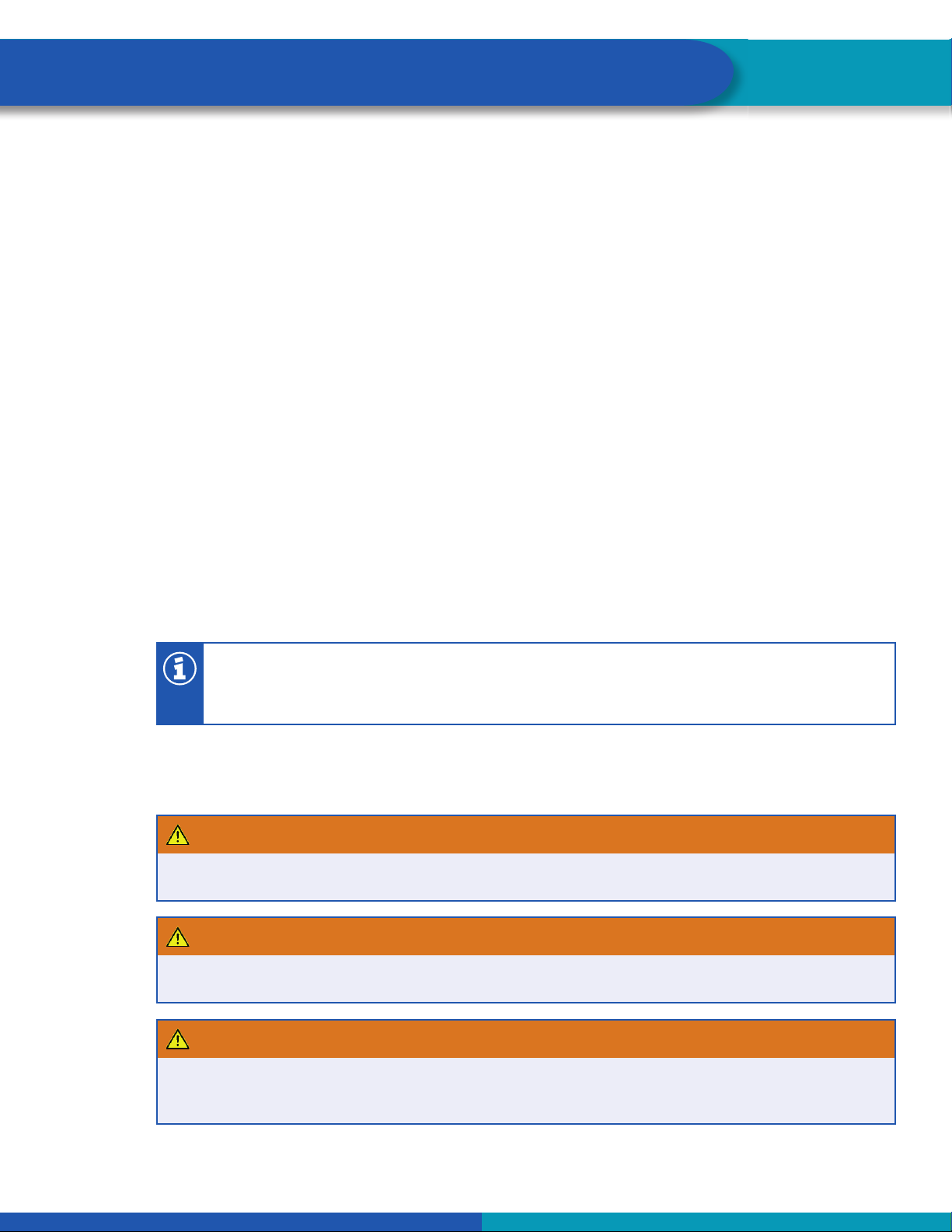
Note 400 612 039 0, 400 612 040 0 and 400 612 041 0 must be used with a WABCO iABS
Premium ECU/Valve assembly 400 500 350 (2S/1M) or 400 500 430 0 (2S/2M - 4S/2M).
Refer to the instructions in this technical bulletin for installing the WABCO Trailer iABS with Lift Axle Control
Option.
4.1 Configuration of Lift Axles by Functionality
The Lift Axle function may be configured in three different ways.
8
Introduction
Each method has its own specific hardware requirement and installation.
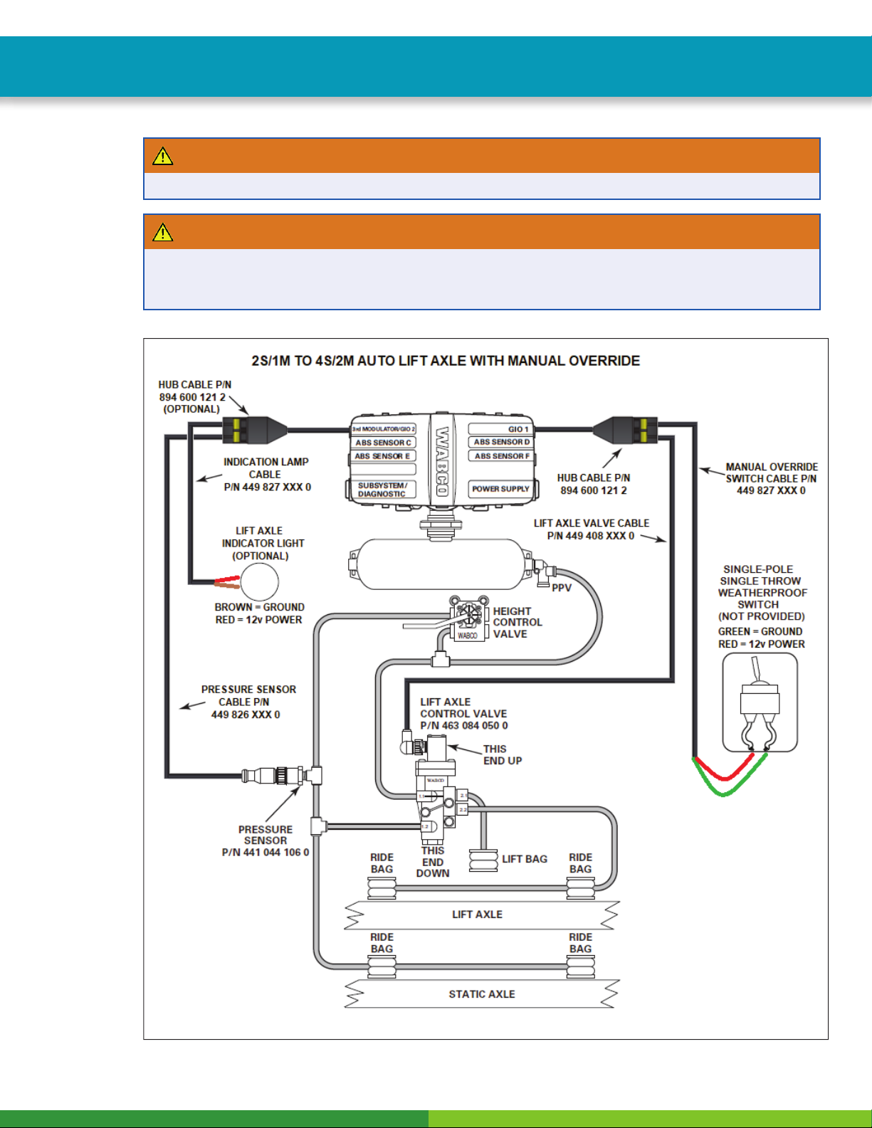
A. Automatic Lift Axle with Manual Override Switch (No spring brake delivery line pressure switch used).
Kit number 400 612 040 0.
This configuration allows the lift axle to automatically raise and lower based upon values put into TOOLBOX
PLUS™ Software which are downloaded into the ECU when it is programmed. This configuration has a
trailer-mounted manual override switch that allows the driver to disable the ECU controlled raise/lower
function and keep the lift axle in the down position. This allows the driver to keep the trailer in compliance
where local ordinances require all lift axles to be kept in the down position regardless of load carried. Refer
to Figure 1 for the Manual Override Switch option.
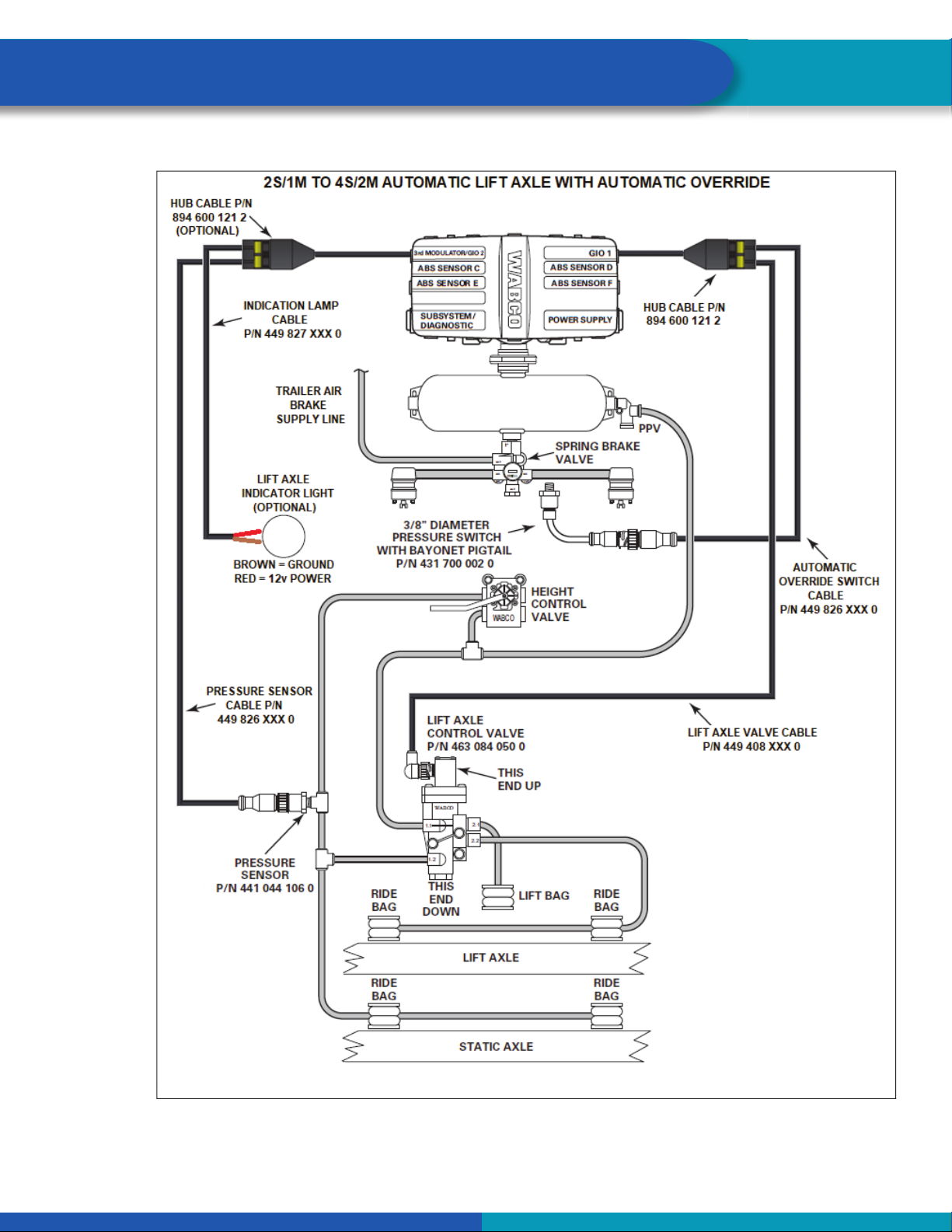
B. Automated Lift Axle with Automatic Override (Spring brake delivery line pressure switch required).
Kit number 400 612 039 0.
This configuration allows the lift axle to automatically raise and lower based upon values put into TOOLBOX
PLUS™ Software which are downloaded into the ECU when it is programmed. This configuration allows
the driver to lower the lifted axle when parked by pulling the red dash valve in the tractor to remove trailer
supply air. This feature is useful for slider positioning or fast loading operations to ensure that the lift axle
is in the down position. Specifically, when the delivery line from the trailer spring brake chamber meets
or drops below 70 psi (4.82 bar), the ECU will automatically lower the lift axle. Refer to Figure 2 for the
Automatic Override Switch option.
C. Automated Lift Axle with Both Manual and Automatic Override. Kit number 400 612 041 0.
This configuration allows the driver to lower the lifted axle by means of a toggle switch or by pulling the red
dash valve in the tractor to remove trailer supply air when the vehicle is at rest. This requires the technician
to perform the installation instructions for both manual and automatic configurations outlined in Step 10.
Refer to Figure 3 for the installation diagram.
A lift axle can be lowered by removing power to the trailer.
4.2 Installation
WARNING
To prevent serious eye injury, always wear safe eye protection when you perform vehicle maintenance or
service.
WARNING
Remove all pressure from the air system before you disconnect any component. Pressurized air can
cause serious personal injury.
WARNING
Park the vehicle on a level surface. Block the wheels to prevent the vehicle from moving. Support the
vehicle with safety stands. Do not work under a vehicle supported only by jacks. Jacks can slip or fall
over. Serious personal injury and damage to components can result.
9
Introduction
WARNING
Ensure the trailer has correct electrical grounding; refer to SAE Specification J1908.
WARNING
When you work on an electrical system, the possibility of electrical shock exists, and sparks can ignite
flammable substances. You must always disconnect the battery ground cable before you work on an
electrical system to prevent serious personal injury and damage to components.
Fig. 1
4017323a
10
Introduction
Fig. 2
4017324a
Table of contents
Other WABCO Automobile Accessories manuals

WABCO
WABCO TP2205 User manual

WABCO
WABCO OnGuard User manual

WABCO
WABCO iABS 2S/1M Standard User manual

WABCO
WABCO IVTM Guide

WABCO
WABCO TP19108 User manual

WABCO
WABCO 2S/2M User manual

WABCO
WABCO Truck Training Model User manual

WABCO
WABCO TP0735 User manual

WABCO
WABCO 971 002 923 2 User manual

WABCO
WABCO OnSide MM16167 User manual


