WAC Lighting ORB F-004 User manual

ORB
Installation Instructions
works with the
Google Assistant

Please read and review instructions
before installation

For all questions about your ceiling fan please read all
included instructions, installation procedures, trouble-
shooting guidelines and warranty information before
starting installation
For fast service have the following information below
when you call:
For missing parts or general inquiries
call our trained technical sta at:
• Model Name and Number
• Part Number and Part Description
• Date Of Purchase and Purchase Location
Email: [email protected]
Or live chat at www.waclighting.com
Email: fansupport@waclighting.com
1-800-526-2588 option 01-800-526-2588 option 3
MON-FRI 8AM-8PM EST MON-FRI 8AM-8PM EST
GENERAL INQUIRIES FAN SUPPORT
DO NOT RETURN TO STORE

For operation, maintenance, and troubleshooting information, visit waclighting.com/help.
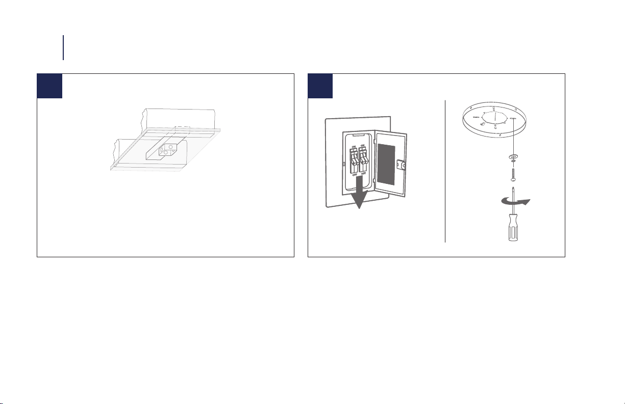
1. To reduce the risk of electric shock, ensure electricity has been turned o
at the circuit breaker before beginning.
2. All wiring must be in accordance with the National Electrical Code “ANSI/
NFPA 70”and local electrical codes. Electrical installation should be per-
formed by a licensed electrician.
3. To reduce the risk of re, electric shock, personal injury or damage to the
fan or other items, the outlet box and support structure must be securely
mounted and capable of reliably supporting a minimum of 35 Ibs (15.9
kg). Use only UL/cUL
listed outlet boxes marked“FOR FAN SUPPORT.” Use only
the screws and washers provided with the outlet box.
4. The fan must be mounted with a minimum of 7 ft. (2.1m)
clearance from the trailing edge of the fan blades to the oor
and a minimum of 1.5 ft (0.5m) from the edge of the fan blades to the
surrounding walls.
5. Never place objects in the path of the fan blades.
6. To avoid personal injury or damage to the fan and
other items, please be cautious when working around
or cleaning the fan.
7. To avoid electrical shock or damage to the motor or nish, do not use wa-
ter or chemicals when cleaning the fan or fan blades. A dry cloth or lightly
dampened cloth will be suitable for most cleaning.
8. After making electrical connections, spliced conductors should be turned
upward and pushed carefully up into the outlet box. The wires should be
spread apart with the grounded conductor and the equipment-ground-
ing conductor on one side of the outlet box, and the
ungrounded conductor on the other side of the outlet box.
9. All set screws must be checked and re-tightened where necessary before
installation.
SAFETY RULES

WARNING: Do not install or use your fan if any part(s) is/are damaged or
missing. This product is designed for use only with the supplied parts and/or
accessories designated for use with this product by WAC. Substitution of parts
or accessories not designated for use with this product by WAC could result
in personal injury or property damage and will void the warranty. Contact an
authorized dealer or the manufacturer if any parts are damaged or missing.
WARNING: To reduce the risk of electric shock, this fan must
be installed and operated with the supplied wall control, or controlled from the
WAC app or Wall Control (not included).
WARNING: Do not use power tools to assemble or install your fan. Using power
tools can result in improper assembly which can lead to noise or fan dam-
age,personal injury or property damage.
WARNING: To reduce the risk of personal injury, do not bend the
blade arms when installing the brackets, balancing the blades or cleaning the
fan.
WARNING: Do not insert foreign objects between rotating fan blades.
WARNING: Do not operate fan unless fan blades are in place.
Noise and fan damage can occur
WARNING: This appliance is not intended for use by young
children without supervision.
CAUTION: Before assembling your fan, refer to the“Making
the Electrical Connections“ section. If you feel you do not have
enough wiring knowledge or experience, have your fan installed
by a licensed electrican.
NOTE: Before servicing or cleaning the fan, switch power o at
the circuit breaker.
02 SAFETY RULES

This WAC Smart Fan is:
DC
MOTOR
The WAC app synchronizes seamlessly with smart home devices you already own
GET SMART
WALL CONTROL
WC20-WT
Optional Accessory
Sold Separately
6 fan speeds
Dims light to 1%
ON/OFF
APP DOWNLOAD
Available for purchase on
the Google Pay and App Store
Quiet, reliable, and up to 70%
more ecient than AC motor fans
Wi-Fi and Bluetooth enabled
for unlimited control
Wet/Damp location-listed to the
strictest UL/cUL safety regulations
Compatible with our WAC app
Coordinate with smart devices
for voice-activated control
REMOTE CONTROL
RC20-WT
Included with
each fan
6 fan speeds
Dims light to 1%
ON/OFF
works with the
Google Assistant

Package Contents
Mounting Options
Installing the Mounting Bracket
Attaching the Fan Blades
Hanging the Fan
Making the Electrical Connections
Installing the Optional Wall Control
Installing the Adapter Plate
Installing the Luminaire Module
Finishing the Installation
Controlling the Fan
Factory Reset
App Instructions
Accessories
Troubleshooting
9.
10.
10.
11.
12.
12.
13.
14.
15.
17.
18.
21.
22.
24.
25.
4
7
7
8
9
10
11
12
13
14
15
16
5
5
6
TABLE OF CONTENTS

F-0048
Electrical tape
Phillips screwdriver Step ladder Wire cutters
NOTE: Before discarding packaging materials, be certain all parts have been removed.
NOTE: Place the parts from the hardware bag into a small container to keep them from being lost.
MAC ID
03 TOOLS & MATERIALS REQUIRED
IMPORTANT: Please make note of the MAC ID on the receiver and keep it in a safe place.

9F-004
NOTE: ** denotes nish code of fan
33
1
8
9
2
7
12
5
4
6
10
11
Receiver
F-R3-004-044
Hardware Bag
RPL-F004-PARTS
Screw Bag
(Optional)
RPL-F004-PARTS
Fan Blade
RPL-F004-44-BD-**
LED Module
(F-004L version)
F4IN-120V-R1-30
Glass Shade Cap
(F-004L version)
RPL-F004-GLA
Metal Light Cover
RPL-F004-COVER-**
Safety Cable
5.4mm Spring
Washers (2pcs)
Safety Cable
5/32” Spring
Washers(2pc)
Safety Cable
10 x 4mm x 0.8H
Flat Washers (1pc)
Hanger Bracket
8 x 3/4” Machine Screws(2pcs)
F-004L with Light Kit
Includes
5/32*8mm Philips Head
Screw(3pcs)
Hanger Bracket
12 x 11W x 2”L Philips
Self-Tapping Screws (2pcs)
Blade Arm and Blade
3/16” x 10mm Blade
Screws(10pcs)
Blade Arm and Blade
14 x 4.4 x 2T Nylon
Washers(10pcs)
Motor Housing
Luminaire Plate
(F-004L version)
Trim Ring -
Decorative
RPL-F004-TRIM-**
Adapter Plate
Mounting Bracket
RPL-F004-HGR
PACKAGE CONTENTS 04
Remote Control
RC20-WT

F-00410
1 2
05 MOUNTING OPTIONS INSTALLING THE MOUNTING BRACKET
1. Remove 1 set screw from mounting bracket and set aside for use
in Finishing the Installation.
2. Pass supply wires through mounting bracket and secure to
outlet box.
Standard Ceiling Caution: To prevent electrical shock, ensure
electricity has been turned o at the circuit
breaker before beginning.
CAUTION: To prevent electrical shock, ensure electricity has been
turned o at the circuit breaker before beginning.
Mount to the outlet box as shown above.

11F-004
3
ATTACHING THE FAN BLADES 06
1. Place blade into motor housing.
2. Insert blades in slots, aligning with motor assembly holes.
3. Secure blades with blade attachment screws & washers.

F-00412
07 HANGING THE FAN MAKING THE ELECTRICAL CONNECTIONS
120V Wires
UL/cUL Listed
outlet box
Mounting
Bracket
Mounting screws
supplied with
outlet box
5 6 Outlet Box
Mounting Bracket
(Mounting Bracket Ground)
Motor
Trim Ring
Safety Cable
Wood Screw
1. Connect the labeled wires from fan to the corresponding wires
on the receiver.
2. Connect the labeled wires from the outlet box to the
corresponding wires on the receiver.
1. Remove 2 opposing screws and loosen the other 2.
2. Pass supply wires through mounting plate.
3. Place trim ring onto the canopy. Opening of 4 clips facing up.
4. Lift motor assemby and hang it on the hook on the mounting
plate using one of the screw holes.
5. Secure the safety cable to the building structure using a wood
screw (not included) (Fig. 9).
NOTE: Safety cable is required for all ceiling fan installations in
Canada. Safety cable is required for ceiling fan and light (combo)
installations over 35 lbs. in both ush and downrod models in the
United States.

13F-004
7
INSTALLING THE OPTIONAL WALL CONTROL 08
NOTE:Wall control not included. A Bluetooth wall control accessory can be purchased separately.
NOTE: For multi-location wiring, skip to the next step.
1. Connect the green wire marked“GROUND” from the wall control to the copper wire from the wall outlet box that
feeds back to the circuit breaker – important for proper fan function.
2. Connect the black wire marked “LINE IN”from the wall control to the black LINE VOLTAGE wire from the wall
outlet box that feeds back to the circuit breaker.
3. Connect the red wire from the wall control to the black wire from the wall outlet box that feeds up to the fan.
4. Connect the white wire from the wall control to the white (neutral) wire from the wall outlet box.
5. Carefully tuck the wire connections inside the outlet box. Secure the wall control with the two (2) wall control screws provided.
6. Attach the wall mounting plate over the wall switch and secure with the two (2) wall mounting plate screws provided.
7. Fasten the wall plate to the wall mounting plate.

F-00414
9
8
1. Remove 1 of 3 screws from the mounting ring and loosen the
others (do not remove).
2. Install the adapter plate, by screwing in the previously removed
screw and tightening the others.
09 INSTALLING THE ADAPTER PLATE / FINISHING THE INSTALLATION
1. Secure wire connectors with supplied wire ties.
2. Remove the motor from the hook on the mounting bracket. Slide
the motor up to the mounting bracket and place the key hole on
the motor over the screw on the mounting bracket. Turn motor
until it locks in place at the narrow section of the key holes.
3. Align the circular hole on canopy with the remaining hole on the
mounting bracket. Secure by tightening the two screws previously
loosened and the two screws previously removed.
4. Raise up trim ring and line up the 4 tabs with the 4 grooves on
the mounting bracket. Once lined up, slide the trim ring and secure
it to the canopy until snug.

F-004 15
10
INSTALLING THE LUMINAIRE COVER 10
NOTE: Skip to next step if you purchased the luminaire version.
1. Install metal light cover rmly without over-tightening.

11
16
12
1. Run LED wires from motor housing through the adapter and
luminaire adapter plates.
2. Connect white wire to white wire and black wire to blue wire.
NOTE: Do not screw in luminaire plate until LED wires are
connected.
10 INSTALLING THE LUMINAIRE MODULE & GLASS
(When installing F-004L)
1. Remove 1 of 3 screws from the adapter plate and loosen the
others (do not remove).
2. Using the screw from the previous step, install the luminaire
plate.
3. Secure the LED module to the luminaire plate using the 3
screws provided in the screw bag.

13 14
17
FINISHING THE INSTALLATION 11
1. Install glass shade without over-tightening.

F-00418
15 16 17
A
A
B
B
C
C
Your fan was delivered to you with the included control already
paired to your fan. You will need to remove the pull-tab to begin
using your remote control.
A: Light On/O, Bright/Dim
B: Fan On/O, Speed Up/Down
C: Season (Summer/Winter)
Air-Gap Switch: Pull tab to power o in case of emergency.
Not necessary for normal fan operation (only included with
wall control).
Air-Gap
Switch*
Pairing
Press and hold buttons
for 10-15 seconds.
Wall Control
* Air-Gap Switch only included
with wall control
Remote
Control
Unpairing
To purge, press and hold
buttons for 4 seconds.
Summer Mode
(Counter-Clockwise)
Winter Mode
(Clockwise)
NOTE: Your fan features 6 speeds. An audible tone will indicate
when the speed is increased or decreased. When the fan has
reached the minimum/maximum speed level the fan will beep
twice.
NOTE: Pairing must be completed within 3 minutes of turning
the power on to the fan receiver.
12 CONTROLLING THE FAN

19F-004
Controlling Multiple Fans with Remote or Wall Controls
Your remote and wall controls are capable of controlling
multiple fans. A remote or wall control has the ability to control
an unlimited number of fans with the only limitation being the
Bluetooth® range of the control and fan.
Pairing a remote control or wall control to an additional fan(s)
can be performed in the same manner as described in the
pairing section.
NOTE: Pairing must be completed within three (3) minutes of
powering the fan.
Synchronizing Control Across Multiple Fans
If you are controlling more than one fan with a remote control,
there is a possibility that their light state, fan state or fan
direction can get out of sync. To bring the fans/lights back
into sync please follow the instructions on the next page.
Breeze Mode
1. Breeze Mode mimics the natural ebb and flow of winds in
nature by varying the fan speed.
NOTE: Breeze Mode always rotates your fan in the Summer
(CCW) direction
2. To start Breeze Mode, press and for 4 seconds. The
LED will blink green and the fan will beep.
3. To exit Breeze Mode and return to standard fan mode,
press and for 4 seconds. The led will blink green and
the fan will beep. Your fan will return to the direction and
speed it was set to prior to entering Breeze Mode.
CONTROLLING THE FAN 12

F-00420
23
12 CONTROLLING THE FAN
Fan On/O: Press and hold button for 4 seconds. The LED on the remote will ash green and all connected fans will beep to
indicate the message has been received. All fans will turn o. This will bring all fans controlled by the remote into sync.
Light On/O: Press and hold button for 4 seconds. The LED on the remote will ash green and all connected fans will beep to
indicate the message has been received. All lights will turn o. This will bring all fans controlled by the remote into sync.
Fan Direction: Press and hold button for 4 seconds. The LED on the remote will ash green and all connected fans will beep to
indicate the message has been received. All fans will be set to summer mode (CCW rotation). This will bring all fans controlled by the
remote into sync.
Fan On/O
Press and hold
button for 4 seconds.
Light On/O
Press and hold
button for 4 seconds.
Fan Direction
Press and hold
button for 4 seconds.
Table of contents
Other WAC Lighting Fan manuals

WAC Lighting
WAC Lighting CLEAN User manual

WAC Lighting
WAC Lighting AELLA User manual

WAC Lighting
WAC Lighting Blitzen F-060L User manual

WAC Lighting
WAC Lighting San Francisco F-081L User manual

WAC Lighting
WAC Lighting GEOS F-068L User manual

WAC Lighting
WAC Lighting F-001-MW User manual

WAC Lighting
WAC Lighting MOCHA User manual

WAC Lighting
WAC Lighting Clean F-003 User manual

WAC Lighting
WAC Lighting Mocha XL F-064 User manual