WALDIS First 850 User manual

www.tresore.ch
INSTALLATION AND MAINTENANCE INSTRUCTIONS
WALDIS SAFES
RESISTANCE LEVEL IV /V
AS PER EN1143-1

Thank you
Thank you so much for putting your trust in Waldis for your security needs.
You’ve chosen to buy an EN1143-1-certified safe. A high-quality Swiss product
checked and approved by the VdS.
Please read these instructions carefully before setting up your safe!
For any questions, please contact:
WALDIS Tresore AG
Hofwisenstrasse 20
CH-8153 Rümlang
Tel: +41 43 211 12 00
Fax: +41 43 211 12 12
Email: [email protected]

Contents
1. General information ...................................................................................................................1
1.1. Safety instructions ..............................................................................................................1
1.2. Table of weights ..................................................................................................................1
1.3. Regulations and insurance ................................................................................................2
1.4. operating elements.............................................................................................................2
1.5. Set-up ...................................................................................................................................2
2. Installation....................................................................................................................................3
2.1. Positioning against the building wall ................................................................................3
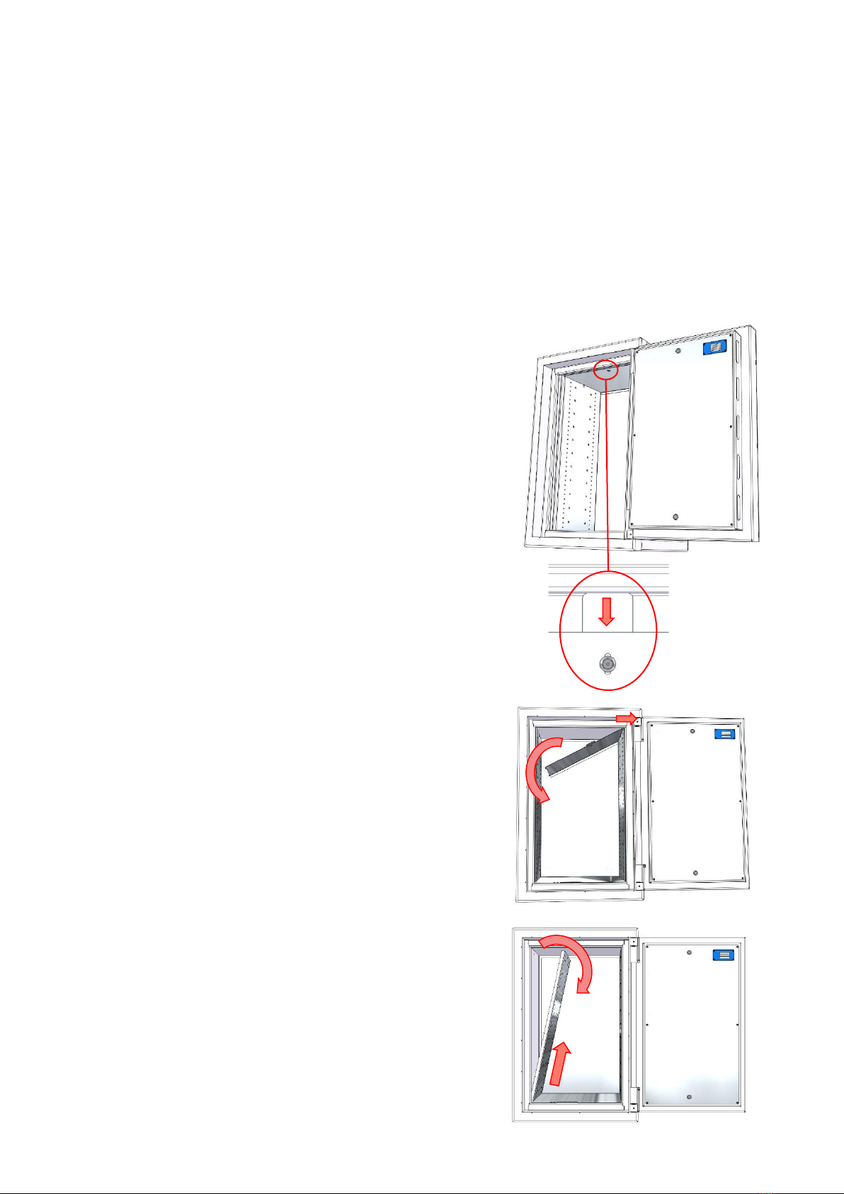
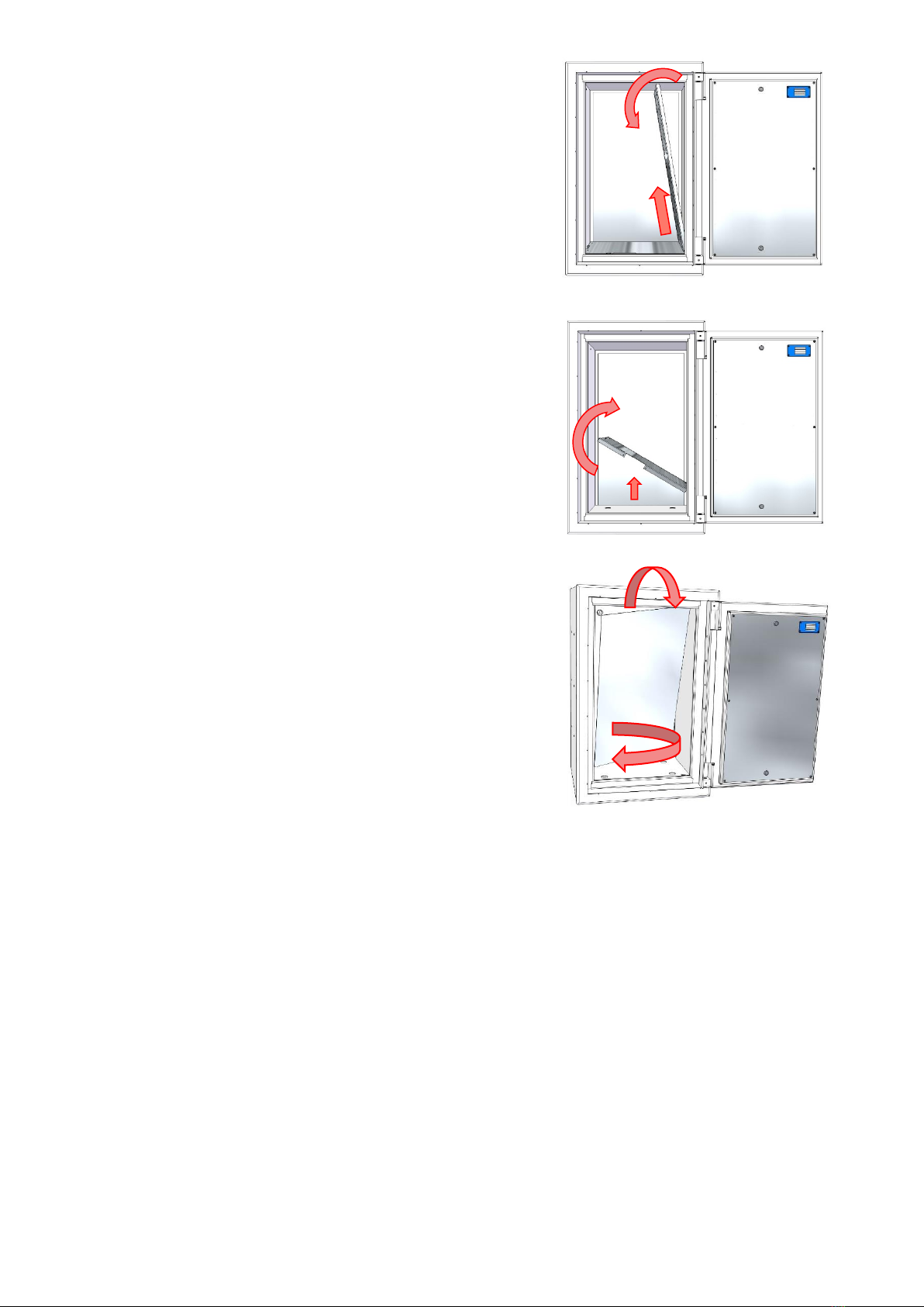
2.2. Disassembly, interior construction ...................................................................................4
2.3. Anchoring the safe..............................................................................................................6
2.3.1. Important prior clarification ........................................................................................6
2.3.2. Preparing the safe .......................................................................................................6
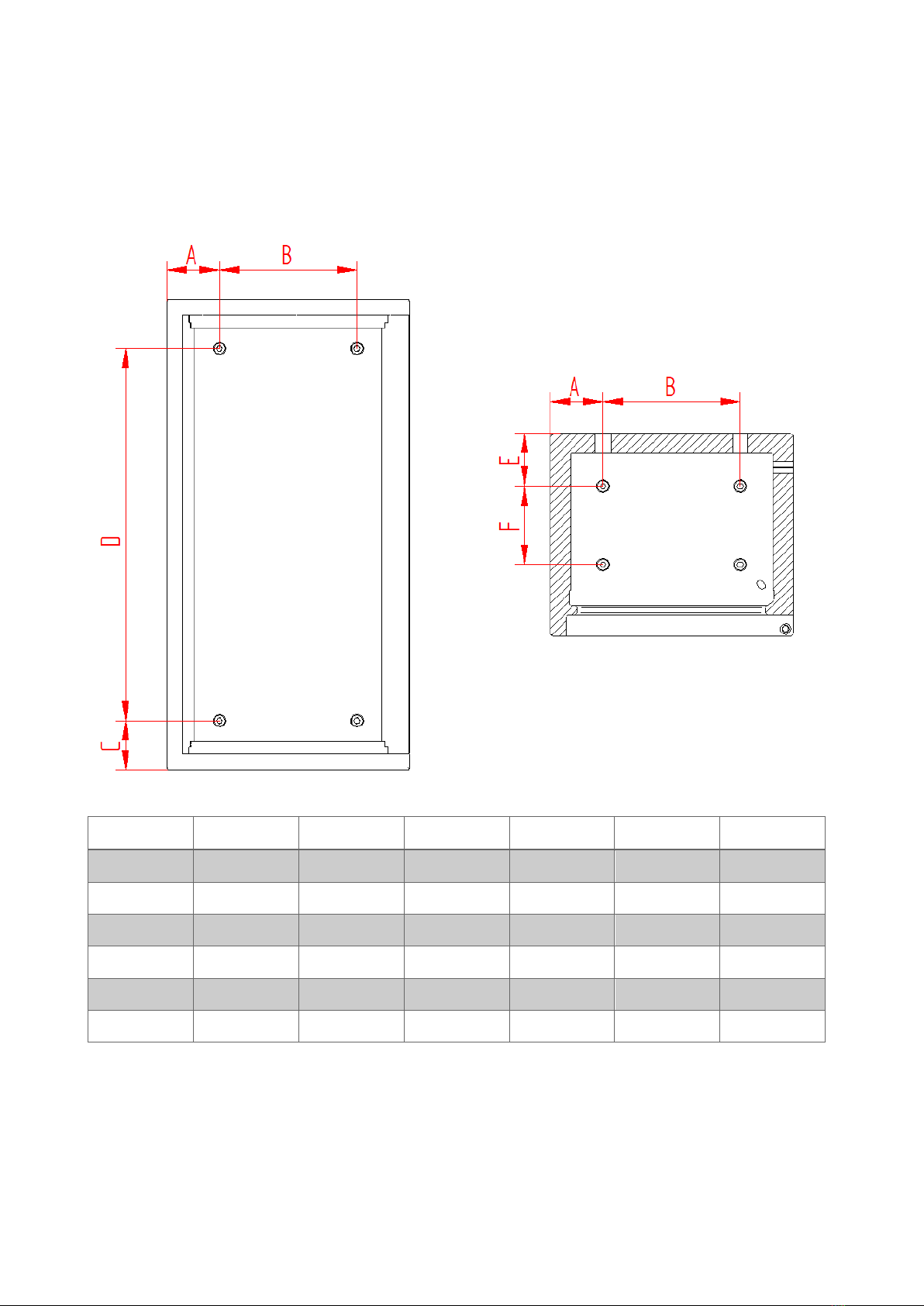
2.3.3. Table for dimensions, anchoring holes ....................................................................7
2.3.4. Procedure .....................................................................................................................8
2.4. Assembly, interior construction ........................................................................................9
2.5. Cable entry / power connection .................................................................................... 11
3. Maintenance and care instructions ...................................................................................... 12
4. Exemption from liability .......................................................................................................... 12
5. Guarantee against theft .......................................................................................................... 13

500.0030-D 1 Technical alterations reserved
1. General information
Every WALDIS First and WALDIS Premium safe is equipped with an electronic security
lock. To operate the lock, please use the 500.0024 / 500.0026 instruction manuals
enclosed. You can find the comprehensive OM_PAXOS_V005_20190222_EN
instruction manual, produced by the manufacturer, at: www.domakaba.com.
1.1. Safety instructions
PLEASE NOTE: Please make sure that no body parts get trapped between the doors and
the case when opening and closing the doors!
PLEASE NOTE: Before closing the doors, make sure that the handle is in the open
position and the bolt is retracted!
1.2. Table of weights
To transport and move the safe, please consult the following table for the weights of the
different models:
Model
Weight (kg)
First 850
560
Premium 850
595
First 1000
635
Premium 1000
675
First 1200
735
Premium 1200
785
First 1500
935
Premium 1500
1000
First 1500-XL
1215
Premium 1500-XL
1300
First 1800-XL
1420
Premium 1800-XL
1515

500.0030-D 2 Technical alterations reserved
1.3. Regulations and insurance
For all safes with a net weight of less than 1000 kg, professional anchoring either during
construction or by the client is a minimum requirement of the EN1143-1 standard. For this
reason, all safes are equipped with 8 bore holes (4 on the back wall and 4 on the base)
with a diameter of 14.5 mm. If it is not possible to anchor the safe in accordance with
current regulations, the property insurance company must be informed and an alternative
solution must be found.
PLEASE NOTE: The safe’s warranty and certification terminate after attempted break-ins,
fires and unauthorised interference with the structure!
1.4. operating elements
Input unit
Handle
PLEASE NOTE: The following instruction manual explains how to operate a safe with the
hinge on the right-hand side of the door! If you have a safe with the hinge on the left-hand
side of the door, all rotation, opening and closing movements must go in the opposite
direction!
1.5. Set-up
The safe is delivered without a battery inserted as standard, meaning it can be opened
and closed without entering a code.
If the battery is inserted and the safe is locked when delivered, please follow the 500.0024
/ 500.0026 instruction manual.

500.0030-D 3 Technical alterations reserved
2. Installation
2.1. Positioning against the building wall
When positioning the safe, please observe the minimum distance (A) from the wall in order
to be able to open the door more than 90º. If you want to be able to use the safe’s full
internal diameter, you also need to observe the minimum distance (B) from the strip side
to the wall so that the door can be opened to 130º. If the door needs to be opened 180º,
observe the minimum distance (C) from the strip side.
You can find the minimum distances to observe for your model in the table below.
Model
A for 90° (mm)
B for 130° (mm)
C for 180° (mm)
850
570
380
570
1000
570
380
570
1200
570
380
570
1500
570
380
570
1500-XL
720
480
720
1800-XL
720
480
720
B / C
A
90°
130°
Safe
Building wall
View from above with building wall
Internal
diameter
Front view (doors opened to 130º)

500.0030-D 4 Technical alterations reserved
2.2. Disassembly, interior construction
To correctly anchor the safe (Section 2.3), its complete chrome-steel interior construction
(lid, side walls, base, and rear wall) have to be completely disassembled. It is important to
remove the individual metal plates with care so as to avoid scratching them.
Follow this procedure to disassemble the safe:
CAUTION: CUTTING DANGER ON THE METAL SHEETS!
1. Open the safe as per the 500.0024 /
500.0026 instruction manual.
2. Pivot the doors as much as possible
(ideally 180º).
3. Release the countersunk screw in the lid
(3mm Allen key) and push the clamping
plate backwards. Then, tighten the
countersunk screw again so that the
clamping plate cannot slide forward any
more.
4. Raise the lid slightly and push it to the
right until the tabs of the lid can be
swivelled past the left-hand side wall.
Once the lid has been swivelled approx.
45º, the tabs can be unhooked on the
right-hand side wall, and the lid can be
pulled out of the safe diagonally.
5. Completely unscrew the cylinder-head
screw located at the top-centre of the
side wall (4mm Allen key), holding the
side wall in place with your hand to
prevent it from tipping over. Then, allow
the side wall to tilt inwards and pull it out
of the plug connection in the base. As
soon as the side wall is separated from
the base, it can be pulled out of the safe
diagonally.

500.0030-D 5 Technical alterations reserved
6. Repeat Step 5 for the right-hand side
wall.
7. Lift the base slightly and then pull it out
of the safe diagonally. Make sure to hold
the rear wall in place with your hand!
8. Allow the rear wall to tilt forwards from
the top and then turn it diagonally
forwards onto one side. Then, carefully
lift the rear wall and pull it out of the safe.
9. Set the disassembled interior
construction to one side so that it does
not get in the way of anchoring the safe
and cannot be damaged.

500.0030-D 6 Technical alterations reserved
2.3. Anchoring the safe
PLEASE NOTE: Assembly and anchoring may only be carried out by WALDIS Tresore
AG’s trained staff or by authorised specialists! WALDIS Tresore AG accepts no liability for
damage to people or property in case of incorrect assembly and anchoring.
2.3.1.Important prior clarification
Check that the building floor and building wall are suitable for installing the safe and that
there are no wires, pipes or similar in the area to be drilled!
In case of doubt, an expert report should be issued to guarantee that the intended
assembly location in the building can withstand the weight of the safe, including its
contents.
2.3.2.Preparing the safe
The four screw plugs (8mm Allen key) must be removed from the interior of the safe
before anchoring it through the rear wall or the base.
Anchoring sleeve
in the safe wall
Screw plug

500.0030-D 7 Technical alterations reserved
2.3.3.Table for dimensions, anchoring holes
In order to drive the supplied drop-in anchor into the building wall or building floor at the
assembly location in advance, please consult the following table of measurements for
drilling patterns for all WALDIS First and Premium models.
Model
A (mm)
B (mm)
C (mm)
D (mm)
E (mm)
F (mm)
850
149
350
125
600
172.5
200
1000
149
350
125
750
172.5
200
1200
149
350
125
950
172.5
200
1500
149
350
125
1250
172.5
250
1500-XL
150
500
125
1250
167.5
400
1800-XL
150
500
125
1550
167.5
400
Front view (without doors)
for rear-wall anchoring
Cross-section view from above
(without doors) for base anchoring

500.0030-D 8 Technical alterations reserved
2.3.4.Procedure
The safe is delivered with 4x cylinder screws with an M12x30 internal hex (DIN 912,
strength grade 12.9), 4x M12 washers (DIN 125 A) and 4x M12x50 drop-in anchors.
If it is not possible to use the installation material specified or it is not possible to anchor
the safe, please consult your property insurance provider to find an alternative anchoring
solution.
Follow this procedure to anchor the safe into the building wall or floor:
1. Draw the drilling pattern on the desired position and then drill the anchoring holes with
Ø15 concrete drill and an impact drill.
➔The Ø15 drill hole must be at least 54 mm (from the wall/floor) or at least 122 mm
(from the safe’s interior wall) deep.
2. The EA2 M12x50 drop-in anchor can be hammered in once all four anchoring holes
have been drilled.
➔Please consult the manufacturer’s information sheet for hammering in the Fischer
EA2 M12x50 drop-in anchor (Fischer no.: 48406).
3. Align the safe with the installation holes in the building wall or the building floor.
4. If the safe is to be anchored to the building wall, it has to be evenly hammered into the
wall evenly.
5. Level out the safe so that the door stands still in any position and does not start to
swing in one direction (open or closed) on its own.
➔To do this, place small hardboards (Pavatex) under the corners required.
6. Attach a washer to each of the cylinder screws and screw them through the anchoring
sleeve into the drop-in anchor (10mm Allen key) until they line up.
7. Tighten the cylinder screws to 35 Nm (10mm Allen key), and then tighten them again
to 35 Nm in the same order to be sure.
If the installation material supplied cannot be used owing to the quality of the floor or wall,
installation has to be adapted to the actual conditions. The dowel used must match the
type of quality of the building material to be anchored into (minimum requirements for
threaded rods, screws and dowels M12: Strength grade 12.9, DIN 975 with ISO 7089
discs). Please observe the manufacturer’s instructions.
Safe wall
Anchoring sleeve
Cylinder-head screw
with washer
Building wall /
Building floor
Drop-in anchor

500.0030-D 9 Technical alterations reserved
2.4. Assembly, interior construction
After anchoring the safe, its chrome-steel interior construction (lid, side walls, base, and
rear wall) has to be completely assembled again. It is important to assemble the individual
metal plates with care so as to avoid scratching them.
CAUTION: CUTTING DANGER ON THE METAL SHEETS!
1. Allow the rear wall to tilt forwards
from the top and then turn it
diagonally onto one side. Then, lift
the rear wall and carefully push it
into the safe.
Push the rear wall evenly backwards
towards the interior rear wall of the
safe.
2. Push the base into the safe
diagonally and carefully set it down
on the interior floor while holding
back the rear wall.
Caution: Make sure that no wires
get caught when setting the base
down!
3. Guide the right-hand side wall into
the safe diagonally and plug it into
the plug connection in the base. As
soon as the side wall is plugged into
the base, it can be stood upright on
the right-hand side and screwed in
(4mm Allen key) at the centre of the
safe using the cylinder screw.
Caution: Only screw in lightly!

500.0030-D 10 Technical alterations reserved
4. Guide the left-hand side wall into the
safe diagonally and plug it into the
plug connection in the base. As soon
as the side wall is plugged into the
base, it can be stood upright on the
left-hand side and screwed in (4mm
Allen key) at the centre of the safe
using the cylinder screw.
Caution: Only screw in lightly!
5. Guide the lid into the safe at an
approx. 45º angle. Clip the tabs of
the lid onto the top of the right-hand
side wall and slowly pivot the lid
upwards. Push the lid slightly to the
right while doing this so that it does
not align to the left-hand side wall
when swivelled up. As soon as the
left-hand tabs of the lid have been
swivelled past the left-hand side wall,
the lid can be pushed slightly to the
left, and the tabs can be clipped onto
the left-hand side wall.
6. Once the lid is laid on both side
walls, it can be pushed backwards
against the rear wall. Pull the
clamping plate forwards and secure
over the countersunk screw (3mm
Allen key) at the same time.

500.0030-D 11 Technical alterations reserved
2.5. Cable entry / power connection
As standard, each safe is equipped with three cable entry openings. These are
located on the right-hand side, in the lower rear area of the safe. If none of the
options listed below have been ordered, they are closed.
1. Mains connection Paxos Advance / Axessor
230V plug-in power supply with approx. 5m cable
length.
2. Alarm preparation
Alarm control cable 12x 0.14mm2 with approx. 5m cable
length.
3. LED illumination
Connection for LED power supply 230V with hollow plug
up to size WA-1200 from size WA-1450
Dimensions (HxWxD) 48x32x76mm Dimensions (HxWxD) 32x50x125mm
4. Power cable pull-in
The power cable for additional interior ttings is "just
pulled" into the safe. The supplied plugs T12 & T13
must be connected by an electrician.
To ensure that no cable breakage or other damage occurs to the cable or the power supply
unit, a lateral distance of at least 5-10cm from the nearest object, furniture, wall, etc. must
be planned.

500.0030-D 12 Technical alterations reserved
3. Maintenance and care instructions
Your safe is essentially maintenance-free. However, we still recommend carrying out a
lubricating and servicing interval as follows, depending on frequency of use but at least
every 12 months:
●Lightly oil the hinges using penetrating oil (e.g. Brunox Turbo Spray).
●Open the door and extend the bolt using the handle, then grease lightly using a
multi-purpose grease (e.g. Motorex 176 GP).
●The chrome-steel interior construction can be cleaned using a standard chrome-
steel cleaner (e.g. Dr. Weigert neoblank spray).
●The varnished surfaces can be wiped down with a damp cloth.
WARNING: Do not clean with household chemical products!
Should any mechanical problems or electrical issues occur, please consult your trusted
specialist dealer or contact WALDIS Tresore AG directly.
4. Exemption from liability
The above guarantee and the theft guarantee include a final provision with regard to the
delivery of the item purchased. Any further liability is completely excluded. As for services
by WALDIS that are to be arranged separately, such as transportation, packaging,
insurance, assembly and installation, WALDIS’ liability is limited to damage caused by
gross negligence or deliberate intent (Art. 100, Para. 1 OR). The customer also recognises
WALDIS’ right to use external companies to fulfil the additional services listed. In this case,
WALDIS’ liability is limited to selecting and instructing the external companies with care
(Art. 399, Para. 2 OR).

500.0030-D 13 Technical alterations reserved
5. Guarantee against theft
WALDIS provides a guarantee against theft from the secure storage unit for safes starting
from resistance level 2 to cover the duration stated in the order confirmation, as per
European standard EN 1143-1. In particularly vulnerable locations, WALDIS may limit this
guarantee or make it subject to additional measures, e.g. an alarm system. In these cases,
the alarm system has to have been functional and activated at the time the theft took place
and the alarm has to have been triggered and relayed. Otherwise, the theft guarantee
terminates immediately.
The guarantee against theft means that, in the event of theft of the secure storage box
anchored by WALDIS at that location, WALDIS is obliged to replace the secure storage
box concerned, but not to cover damages resulting from the theft, or additional costs such
as transportation and assembly of the new secure storage box, or disassembly or disposal
of the old secure storage box. The customer is not entitled to any kind of compensation or
replacement of the contents of the secure storage box. The guarantee against theft only
applies to theft at the location where the secure storage box was positioned and anchored
at least four times in accordance with the current instruction manual either by WALDIS or
an authorised partner company. If the secure storage box is not positioned, anchored or
moved by WALDIS or an authorised partner company, the theft guarantee terminates
immediately.
The safe’s warranty and certification terminate after attempted break-ins, fires and
authorised interference with the structure.
This manual suits for next models
11
Table of contents
Other WALDIS Safe manuals
Popular Safe manuals by other brands

Orbita
Orbita 2043MD user manual

SPORTS AFIELD
SPORTS AFIELD PRESERVE BIOMETRIC Series instruction manual

Phoenix
Phoenix KS0030E Series operating instructions

Hayman
Hayman Ozarks Operation guide

Hard Head
Hard Head 006046 operating instructions

Securikey
Securikey MINI VAULT/FR series Operations & installation guide