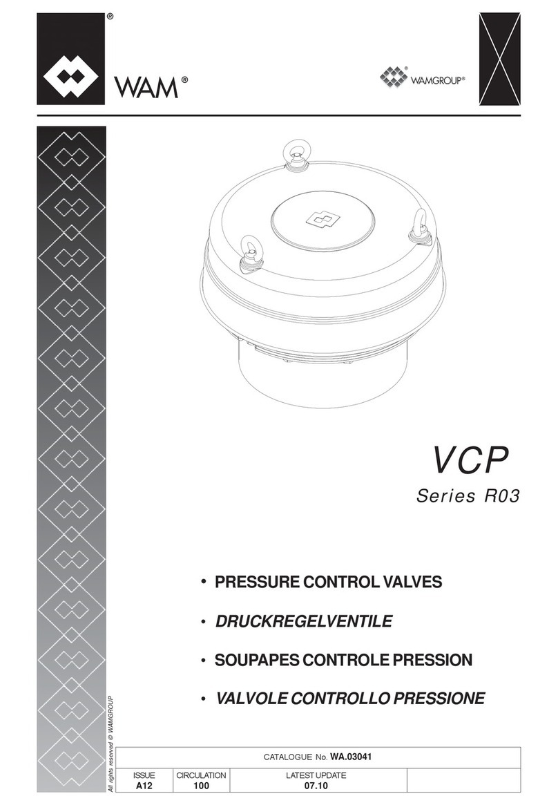
WAMGROUP VCP R03 Series User guide

2
fax
e-mail
internet
+ 39 / 0535 / 618111
+ 39 / 0535 / 618226
www.wamgroup.com
WAMGROUP S.p.A.
Via Cavour, 338
41030 Ponte Motta
Cavezzo (MO) - ITALY
Manual No. VAL.VCP.--.M.A5.1017.EN Issue: A5
Latest Update: October 2017
ORIGINAL INSTRUCTIONS IN ENGLISH
EN VCP
Series R03
SPRING-LOADED PRESSURE
RELIEF VALVES
ASSEMBLY AND
MAIN INSTRUCTIONS
FOR USE AND
MAINTENANCE

All the products described in this catalogue are manufactured according to WAMGROUP S.p.A. Quality System procedures.
The Company’s Quality System, certied in July 1994 according to International Standards UNI EN ISO 9002 and extended to
the latest release of UNI EN ISO 9001, ensures that the entire production process, starting from the processing of the order to the
technical service after delivery, is carried out in a controlled manner that guarantees the quality standard of the product.
This publication cancels and replaces any previous edition and revision.
We reserve the right to implement modications without notice.
This catalogue cannot be reproduced, even partially, without prior written consent by the Manufacturer.

INDEX
VCP
2
VAL.VCP.--.M.A5.1017.EN Issue: A5
10.17
III
1.0 GENERAL INFORMATION ...................................................................................................................... 1
1.1 Scope of the Manual ......................................................................................................................... 1
1.2 Symbols ............................................................................................................................................ 2
1.3 Glossary and terminology ................................................................................................................. 4
1.4 Manufacturer’s data and identication of the valve........................................................................... 5
1.5 Request for assistance...................................................................................................................... 5
1.6 Warranty............................................................................................................................................ 5
1.7 Exclusion of responsibility ................................................................................................................. 6
2.0 INFORMATION REGARDING SAFETY................................................................................................... 7
2.1 General safety prescriptions ............................................................................................................. 7
2.2 Safety prescriptions for transport and handling................................................................................. 7
2.3 Safety prescriptions for installation ................................................................................................... 8
2.4 Safety prescriptions for use and operation........................................................................................ 8
2.5 Safety prescriptions for maintenance and replacement of components ........................................... 8
3.0 TECHNICAL INFORMATION ................................................................................................................. 10
3.1 General description of the valve...................................................................................................... 10
3.2 Main components............................................................................................................................ 10
3.3 Operating principle ...........................................................................................................................11
3.4 Permitted use ...................................................................................................................................11
3.5 Improper use not permitted ............................................................................................................. 12
3.6 Noise level....................................................................................................................................... 14
3.7 Environmental operating limits ........................................................................................................ 14
3.8 Overall dimensions and technical features ..................................................................................... 14
3.9 Safety and information signs........................................................................................................... 15
3.10 Safety devices................................................................................................................................ 15
4.0 INFORMATION REGARDING HANDLING AND TRANSPORT............................................................. 16
4.1 Type of packaging ........................................................................................................................... 16
4.2 Reception of goods ......................................................................................................................... 17
4.3 Lifting and unloading methods ........................................................................................................ 18
5.0 INSTALLATION AND FIXING................................................................................................................. 19
5.1 Recommendations for installation, maintenance and cleaning ....................................................... 19
5.2 Storage............................................................................................................................................ 20
5.3 Supply ............................................................................................................................................. 20
5.4 Calibration ....................................................................................................................................... 20
5.5 Positioning the valve ....................................................................................................................... 25
5.6 Installation and xing of the valve ................................................................................................... 26
5.7 Electrical connection ....................................................................................................................... 28
5.8 Inductive proximity switch ............................................................................................................... 29
5.9 Compressed air connection ............................................................................................................ 30
5.10 Inspection...................................................................................................................................... 31
SUMMARY

INDEX
VCP
2
VAL.VCP.--.M.A5.1017.EN Issue: A5
10.17
IV
6.0 INFORMATION REGARDING USE ....................................................................................................... 32
6.1 Production Start-up ......................................................................................................................... 32
6.2 Shuttdown of the valve at the end of the work cycle ....................................................................... 32
6.3 Long shutdowns of the valve........................................................................................................... 33
6.4 Reuse.............................................................................................................................................. 33
7.0 INFORMATION REGARDING MAINTENANCE .................................................................................... 35
7.1 Cleaning the valve........................................................................................................................... 35
7.2 Lubrication....................................................................................................................................... 35
8.0 REPLACEMENT OF PARTS.................................................................................................................. 36
8.1 Safety recommendations for replacement ...................................................................................... 36
8.2 Returning the valve ......................................................................................................................... 36
8.3 Dismantling and disposal ................................................................................................................ 36
9.0 INFORMATION REGARDING FAULTS ................................................................................................. 37
9.1 Trouble-shooting ............................................................................................................................. 37
9.2 Check-list in case of fault ................................................................................................................ 37
10.0 TECHNICAL DATA ................................................................................................................................. 39
AATTACHMENTS..................................................................................................................................... 40
A1 Nuts and bolts tightening torque Table ............................................................................................ 40

1.0 GENERAL INFORMATION
VCP
2
VAL.VCP.--.M.A5.1017.EN Issue: A5
10.17
1
This Manual has been prepared by the Manufacturer to provide the operating technical information for instal-
lation, operation and maintenance of the valve concerned.
The Manual, which is an integral part of the valve concerned, must be preserved throughout the life of the valve
in a known easily accessible place, available for consultation whenever required.
If the Manual is lost, damaged or becomes illegible, contact the Manufacturer for a copy specifying the serial
number of the valve.
If the valve concerned changes ownership, the Manual has to be handed over to the new owner as part of the
valve supply.
The Manual is meant for specialist technical personnel appointed and authorized by the Manufacturer, owner
and installer to act on the valve concerned for which specic technical skills in the sector concerned are neces-
sary (electrical, mechanical, etc.).
The illustrations may dier from the actual structure of the valve concerned but do not interfere with the expla-
nation of the operations.
In case of doubt, contact the Manufacturer for explanations.
The Manufacturer reserves the right to make changes to the Manual without the obligation to provide prior
notication, except in case of modications concerning the safety level.
The technical information included in this Instruction Manual is the property of the Manufacturer and therefore
has to be considered as condential.
It is forbidden to use the Manual for purposes other than those strictly linked to the operation and maintenance
of the valve concerned.
This information is provided by the Manufacturer in the original language (English) and can be translated into
other languages to satisfy legislative and/or commercial requirements.
1.1 Scope of the Manual

1.0 GENERAL INFORMATION
VCP
2
VAL.VCP.--.M.A5.1017.EN Issue: A5
10.17
2
To highlight certain parts of the text, for purposes of safety, or to indicate important information, certain symbols
are used, the meaning of which is described below.
It is important to comply with and scrupulously follow the information highlighted by the symbols.
Danger - Warning
Indicates situations of serious danger which, if ignored, can be risky for the health and safety of per-
sons.
Caution
Indicates that appropriate behaviour must be adopted to avoid posing risk for the health and safety of
persons and avoid causing economic damage.
Important
Indicates particularly important technical information which must not be ignored.
1.2 Symbols

1.0 GENERAL INFORMATION
VCP
2
VAL.VCP.--.M.A5.1017.EN Issue: A5
10.17
3
Symbol
representation
Symbol description
Danger sign: indicates danger of electric shock caused by the presence of powered
components inside the junction box or control panel.
Obligation: read this Manual before carrying out any action on the valve concerned.
Forbidden: indicates that it is forbidden to lubricate or adjust moving parts.
Danger: indicates danger of serious injury to limbs if the internal moving parts of the
valve are exposed. Before carrying out inspection operations, isolate the valve con-
cerned from the electrical energy sources.
Information: indicates the direction of rotation of the electric motor.
Obligation: indicates the hooking points for lifting of the valve concerned.
Forbidden: indicates it is forbidden to introduce hands into the valve.
List of safety and information symbols

1.0 GENERAL INFORMATION
VCP
2
VAL.VCP.--.M.A5.1017.EN Issue: A5
10.17
4
Operator: person appropriately trained and authorized by the Production Manager for setting up the valve
concerned and carrying out routine maintenance.
Installer: organization with specialized technicians and appropriate equipment for carrying out risk-free instal-
lation and extraordinary maintenance.
Specialist technician: person responsible for and authorized by the Manufacturer, owner or installer to act on
the valve; must have specic technical skills depending on the sector concerned (electrical, mechanical etc.).
The specialist technician, in addition to being familiar with the working of the valve concerned, must be familiar
with the working of the plant or equipment on which the valve concerned is installed.
Routine maintenance: includes all the actions necessary to keep the valve in good working conditions, to
ensure greater operating durability and to keep the safety requisites constant.
Extraordinary maintenance: all the actions meant to keep the valve in perfect working order.
Setting in safety conditions: all the precautions the authorized personnel must adopt before acting on
the valve concerned.
The precautions are listed below.
- Ensure that the valve concerned is disconnected from all the mains and appropriate devices are
used to prevent these from being reconnected accidentally.
- Ensure that all the moving parts of the valve have come to a complete stop.
- Ensure the temperature of the valve concerned is such that it does not burn.
- Provide appropriate lighting in the area around the operations.
- Wait for the material to be handled inside the valve concerned to settle down completely.
1.3 Glossary and terminology

1.0 GENERAL INFORMATION
VCP
2
VAL.VCP.--.M.A5.1017.EN Issue: A5
10.17
5
1.4 Manufacturer’s data and identication of the valve
Important
Do not change the data on the identication plate.
Keep the ID plates clean, intact and legible as regards the data they contain.
If the ID plate is damaged or is no longer legible (even just one informative element on it) contact the
Manufacturer for a new ID plate and replace it.
The ID plates shown identify the valve concerned and its main components.
The plates show the reference necessary for operating safety.
1) Type of valve
2) Serial No.
3) Code
4) Factory setting
5) Standard setting
6) Characteristic colours of springs for standard
settings
7) Manufacturer’s name and address
8) Year of manufacture
For all technical assistance, contact the Manufacturer’s service network.
For all requests, provide the valve identication data, the type of problem encountered and all other information
which could be useful for identifying the problem.
The conditions for validity and applicability of the warranty are specied in the sales contract.
1.5 Request for assistance
1.6 Warranty
WAM S.p.A. via Cavour 338-Ponte Motta / Cavezzo (MO) - ITALY
WAMGROUP
Serial N0.:
TYPE:
Year
COD: 063001722
Factory Setting
+500 mmH2O
-50 mmH2O
Different setting
+300 mmH2O
+800 mmH2O
Spring colour
Green
Red
-100 mmH2O Yellow
7
6
2
1
5
43
8
ID plate is placed on the Excess Pressure Lid, under the Weather Protection Cover.

1.0 GENERAL INFORMATION
VCP
2
VAL.VCP.--.M.A5.1017.EN Issue: A5
10.17
6
The valve is delivered according to the specications indicated by the Buyer in the order and the conditions
valid at the time of purchase.
The Manufacturer shall not accept responsibility for safety of persons or objects and operation failure of the
valve if the loading/unloading operations from trucks, transport, positioning at the site, use, repairs, mainte-
nance etc. have not been carried out in compliance with the warnings described in this Manual, and in accord-
ance with the national legislation in force.
Likewise, the Manufacturer shall not accept any responsibility if the valve concerned is used:
- improperly;
- by unauthorized persons and/or persons not suciently trained for installation, operation and maintenance;
- with modications made to the original conguration without the Manufacturer’s permission;
- with spare parts that are not original or are not specic for the model;
- without maintenance;
- non-pursuant to the regulatory standards and national or local legislation on the matter of occupational
safety;
- non-pursuant to the recommendations in this Manual or on the warning and danger plates applied on the
valve.
1.7 Exclusion of responsibility

2.0 INFORMATION REGARDING SAFETY
VCP
2
VAL.VCP.--.M.A5.1017.EN Issue: A5
10.17
7
Read the Instruction Manual carefully and strictly follow the instructions it includes, especially those
regarding safety.
Most accidents at the workplace are caused by negligence, failure to follow the most elementary safety
regulations and incorrect or improper use of tools and equipment.
Accidents can be prevented and avoided by taking due care, using suitable equipment and adopting
adequate preventive measures.
Apply and comply with the standards in force regarding workplace hygiene and safety.
The personnel trained for and authorized for the operations has to have the psychological/physical
requisites, experience in the sector concerned and the necessary technical skills for carrying out the
operations assigned to them.
All workers involved in any kind of operation must be prepared, trained and informed as regards the
risks and the behaviour to be adopted.
Pay attention to the meaning of the notices applied on the valve, keep these legible and respect the
information indicated.
Use instruments, equipment and tools that have been approved and are intrinsically safe, and cannot
alter the safety level of the operations or damage the valve during installation, use and maintenance.
Modications to the valve components should not be made for any reason whatsoever, without the
Manufacturer’s permission.
Carry out all the handling and transport operations in accordance with the procedures and instruc-
tions shown on the packaging and in the Manual supplied.
All the operations must be performed by qualied authorized personnel.
Those authorized to carry out the handling operations must have the capabilities and experience re-
quired to adopt all the necessary measures to guarantee one’s safety and the safety of persons di-
rectly involved in the operations.
The chosen features of the lifting and handling means (crane, bridge crane, forklift truck etc.) must
take into account the weight to be handled, the dimensions and the gripping points.
During lifting use only accessories such as eyebolts, hooks, shackles, spring hooks, belts, slings,
chains, ropes etc., that have been certied and are suitable for the weight to be lifted.
During handling respect the prescriptions applicable for handling loads.
Keep the position of the valve concerned and the loose components horizontal, keep the load low and
make all the necessary movements gently.
Avoid sudden manoeuvres, dangerous oscillations and rotations, accompanying the movements man-
ually and place the load gently on the ground.
2.1 General safety prescriptions
2.2 Safety prescriptions for transport and handling

2.0 INFORMATION REGARDING SAFETY
VCP
2
VAL.VCP.--.M.A5.1017.EN Issue: A5
10.17
8
Before starting with installation, a “Safety Plan” must be implemented to safeguard the personnel di-
rectly involved and those who carry out operations in the surrounding area.
All the laws must be strictly applied, especially those concerning workplace safety.
Before proceeding with installation operations, mark o the work area to prevent access by unauthor-
ized persons.
The electrical connections must be made in compliance with the standards and laws in force.
The person in charge of making the electrical connections has to ensure that the required standards
and laws are respected before testing.
Do not tamper with the valve concerned by using any kind of device to obtain performances dierent
from those designed.
All unauthorized changes can aect the health of people and the integrity of the valve.
The operators have to exclusively wear protective clothing and have to be equipped with appropriate
individual protection devices for carrying out the operations and as required by the safety and work
accident prevention standards.
Before use, ensure that all the safety devices are installed and that they are working properly.
During operations, prevent access to the work area by unauthorized persons.
Remove all obstacles or sources of danger from the work area.
It is strictly forbidden placing any improper load on the valve.
Danger - Warning
Before carrying out any operation on the valve concerned, ensure it is switched o and disconnected
from all mains and use suitable devices to prevent the possibility of the power sources being activated
accidentally.
Maintain the valve concerned in the conditions of utmost eciency compliant with the maintenance
plan provided by the Manufacturer.
Good maintenance apart from preserving the functional features and essential safety features over
time, will also allow extending the working life of the valve concerned and achieving the best possible
performance.
Strictly follow the procedures indicated in the Manual, especially those concerning safety.
Ensure that all the safety devices are active and working properly.
Mark o the work area in such a manner as to prevent the access of unauthorized persons.
Replace the worn and damaged components exclusively with original spare parts, whose safety, reli-
ability and interchangeability have been undoubtedly established.
2.3 Safety prescriptions for installation
2.4 Safety prescriptions for use and operation
2.5 Safety prescriptions for maintenance and replacement of components

2.0 INFORMATION REGARDING SAFETY
VCP
2
VAL.VCP.--.M.A5.1017.EN Issue: A5
10.17
9
Apart from invalidation of the warranty, the Manufacturer declines all responsibility for damage to
objects and harm to persons deriving from the use of non-original spare parts or due to modications
made during repairs without express written authorization.
Use the oil and lubricants recommended by the Manufacturer.
Do not dump polluting material (oil, grease, paint, plastic etc.) in the environment, but carry out waste
separation disposal depending on the chemical composition of the various products in compliance
with the legislation in force.
On completion of maintenance or replacement operations, before resuming production, check that no
foreign bodies (rags, tools etc.) have been left inside the valve concerned.

VCP
3.0 TECHNICAL INFORMATION 2
VAL.VCP.--.M.A5.1017.EN Issue: A5
10.17
10
VCP Pressure Relief Valves consist of a cylindrical casing with a bottom ange to be connected with a spigot
welded on the silo roof, a disc shape inner steel lid for negative pressure operation held in position by a cen-
tral spring rod, an outside steel ring for excess pressure kept in position by three spring rods, gaskets, and a
weather protection cover.
In the VCP Pressure Relief Valve, helical springs keep the valve lids closed when the pressure value remains
within the preset limits. The three outside spring rods keep the external ring-shaped lid rmly closed as long
as the force generated by the pressure inside the silo does not overcome the spring force. Once the pressure
exceeds the preset value the lid is pushed up and the pressure can escape. The smaller lid covers the central
circular opening of the external lid from below. It is held in the middle by a single spring rod and is pressed
onto the external lid by the normal air pressure inside the silo. In the event of suction pressure, the spring is
compressed and allows the lid to drop. The air entering the silo from outside ensures rapid pressure balance
and pushes the central lid back up into the “closed” position
Important
The terms “equipment” and “valve” used in this manual refer to the same machine.
As components meant for installation in a plant, the valves - not fully provided with safety means -
have to be considered “partly completed machinery”. Therefore, they do not bear an EC marking.
It is forbidden to start the valve unless the machine/plant in which it is to be installed has been de-
clared compliant with the Directive 2006/42/EC and further modications.
3.1 General description of the valve
3.2 Main components
A) Negative pressure Lid
B) Adjustment kit (Springs)
C) Equipped for inductive proximity sensors
D) Excess pressure lid
E) Weather protection cove
F) Weld-on spigot
A
B
C
D
E
F

VCP
3.0 TECHNICAL INFORMATION 2
VAL.VCP.--.M.A5.1017.EN Issue: A5
10.17
11
3.4 Permitted use
These valves are specially designed for use with powder material and granules. The Manufacturer shall not
be liable for any other use.
The valve is designed and manufactured so as to avoid abnormal overheating during operation. The valve
must be installed with enough space around it to allow assembly/disassembly, cleaning and maintenance
operations.
If the valve is to be used with very hot materials, such that the surface temperature exceeds 60°, the installer
must provide for insulating of the valve or installing mechanical barriers to prevent access to very hot parts;
there have to also be applied on the valve the necessary warning signs or pictograms that indicate these risks.
The VCP valve has the following features:
- The valve body can withstand an overpressure P=1bar (10000 mm H20, 100Kpa)
- The paint coating of the valve disc (if present) is < 200 micron thick.
- The valve body is provided with a ange and it can be connected directly to the silo.
- However, a spigot is provided to be welded to the silo, where the valve will then get bolted.
Once assembled, the valve ensures sealing against dust.
The use of valves in the presence of dust with features more severe to what previously indicated or in areas
with dierent classication, is directly and exclusively under the liability of the user.
The VCP Pressure relief valve food version (model GF), compliant to EC 1935/2004, are suitable for applica-
tion with E simulant, max. temperature of 80 °C and 3 days constant in-contact time.
3.3 Operating principle
The Spring-Loaded Pressure Relief Valve are used in all plants where it is required to control excess pressures
or negative pressures, if any, that may be created inside the containers, thereby preventing their breakage or
deformation.
The VCP valve is not controlled by an external device.
It starts working automatically whenever there is a pressure imbalance within the silo due to lling or emptying
of the silo by means of any system. (UNI ISO 8456 5.1.1.4.2 and 5.1.1.4.3).
Size 375 complies to HSE (0- 9540853-0-2).
NOTE: Appropriate maintenance as described in the relevant section of this Manual will considerably increase
the life duration of the valve. This is particularly important when the material handled tends to harden
or get compacted due to shut downs for a certain period of time.

3.5 Improper use not permitted
VCP
3.0 TECHNICAL INFORMATION 2
VAL.VCP.--.M.A5.1017.EN Issue: A5
10.17
12
Danger - Warning
Uses not permitted: the valve must be used only for the specic purpose envisaged by the Manufac-
turer.
Specically:
- do not use the valves if they have not been installed correctly in accordance with the standards in force.
- do not use the valves if the gaskets are not intact.
- do not use the valve as a support even if it is not in operation. In addition to falling, there is risk of damage
to the valve.
The plant installer/installation technician is responsible for providing and installing all the safety devices to
avoid damage to objects or persons in case of breakage and falling of pieces.
WARNINGS
1) The Manufacturer shall not accept liabilities related to the safety of the personnel or damages to objects or
valve failure unless if the operations involving loading/unloading from trucks, transport, positioning at the
site, use, repairs, maintenance, etc. have be carried out in compliance with the warnings described in this
Manual. Likewise, the Manufacturer shall not accept any responsibility if the valve is used:
- improperly;
- by unauthorized persons or those not suitable trained for the job;
- with modications to the original conguration;
- with spare parts that are not original or are not specic for the model;
- non conforming to the standard and legislation currently in force;
- not conforming to the recommendations in this Manual.
2) Before carrying out any operation, the user must make sure the work area is clear of obstacles (persons or
machines) which represent potential sources of danger.
3) Operations involving lifting, transport, installation at the site, commissioning, checking the stability and
working, routine and extraordinary maintenance, etc. must be performed by qualied, authorized personnel
who must operate in accordance with the indications given in this Manual and in compliance with the safety
regulations in force.
4) When installing the valve, it must be connected to the earth wire.
5) It is forbidden to carry out maintenance, repairs or modications while the valve is running. Before carrying
out any operation, disconnect all the electrical and compressed air supplies that may be connected directly
or indirectly to the valve.
6) Before installation of the VCP valve, the plant technician/installer must check the pressure and negative
pressure for which the VCP valve has been calibrated (values indicated on the rating plate) to make sure
these suit the limits tolerated by the container on which the valve is to be applied.
7) Installation of the VCP valve by the installer/plant technician must be done according to the indications given
in this Manual. The installer/plant technician must carry out the functional check as well as the adjustment
and checking of the correct positioning.
8) Disassembly/assembly operations, if any, of the valve are only performed for maintenance and/or cleaning
and they must be carried out only by authorized persons qualied for such operations: the indications nec-
essary for disassembly of some parts of the valve are enclosed to the User manual.

VCP
3.0 TECHNICAL INFORMATION 2
VAL.VCP.--.M.A5.1017.EN Issue: A5
10.17
13
9) Every time the calibrated pressure value is exceeded, the valve will open and release an air-dust mixture (a
dust cloud) to the outside, but only during the activation phase due to overpressure. The VCP valve is suit-
able for use on pressurized or vacuum containers not subjected to special testing or legislation.
The only function of the valve is to safeguard containers, lters and other equipmets from overpressures or
negative pressure outside the tolerance limits.
Specic type of valves are required to safeguard the operator or the environment impact.
10) Make sure the material handled inside the container is not hazardous: according to standard UNI-EN
626-1 § 3.2, any chemical or biological agent that endangers the health is classied as being a hazardous
substance, because:
- highly toxic;
- toxic;
- harmful;
- corrosive;
- irritant;
- sensitizing;
- carcinogenic;
- mutagens;
- teratogenic;
- pathogens;
- asphyxiating.
The user/plant technician must provide the necessary measures while using the VCP with hazardous sub-
stances to reduce atmospheric emissions in accordance with standard UNI-EN 626-1 Appendix A.2. This situ-
ation occurs rarely; however, the installer/plant technician must delimit an area around which personnel is not
allowed during pressurized loading of the silo.
11) This Manual requires setting the entire plant in safety condition before acting on the VCP valve.
NOTE: Remember that, to avoid or reduce futile activation of the valve:
- The permitted pressures must be followed during silos loading phase. The recommended pressure
values must stay lower than 1.5 bar, according to the standards in force.
- The valve maintenance shall be carried out as indicated in the User Manual.
- Install properly sized lters.
- The lters must be submitted to maintenance according to the indications given by the manufacturer.
- The VCP valve must be installed at the top of the silo.
For assembly, maintenance and cleaning, the operator/maintenance personnel must use suitable means, for
example: overhead work platforms, fall preventing devices for personal protection, etc., meant to carry out the
operations required in complete safety.
The VCP valves are not suitable for applications with liquids or uid dierent from atmospheric air.

3.6 Noise level
3.8 Overall dimensions and technical features
VCP
3.0 TECHNICAL INFORMATION 2
VAL.VCP.--.M.A5.1017.EN Issue: A5
10.17
14
For the exact identication of the valve concerned, see the identication plate.
The shipping document shows the diameter of the Spring-Loaded Pressure Relief in addition to the serial
number and identication codes.
Information regarding the technical features of the VCP Spring-Loaded Pressure Reliefs, such as diameter and
seal and disc characteristics is given in Chapter 10.
The only source of noise on the valve is due to the air that passes through during operation.
The VCP valve is usually installed on the top of silos, i.e. in places where exposure of operators is limited. Dur-
ing maintenance, the plant must remain stationary, so there is no noise from the valve. Because of the limited
frequency (occasional) of valve operation and the distance of the operators, risks due to noise are excluded.
Danger - Warning
Depending on the installation site, the installer must adopt suitable systems (barriers, etc.), if neces-
sary, to maintain the noise levels within the legally permitted limits.
3.7 Environmental operating limits
Unless otherwise specied, the valve concerned may be used only within the limits indicated.
- Altitude: less than 1,000 m at sea level
- Environmental temperature: between - 20 °C and + 40 °C
- Cold climates: with temperature less than 5 °C use oil and lubricants suitable to the operating temperature.

3.9 Safety and information signs
VCP
3.0 TECHNICAL INFORMATION 2
VAL.VCP.--.M.A5.1017.EN Issue: A5
10.17
15
Danger - Warning
Follow the signs on the plates.
The plates have to be readable; if they are not, clean them, replace the damaged ones and place them
in their original position.
NB: See page 2, 1.2 Symbols
3.10 Safety devices
The access to the internal parts of the valve is forbidden during operation.
Extraordinary access is provided for removing foreign bodies and material deposits from inside the valve or for
extraordinary maintenance.
For accident prevention it is essential to keep the valve out of personnel reach during operation. To this pur-
pose, the customer has to provide suitable safety devices such as grids, as well as protective inlet and outlet
joints (either robust exible sleeves or rigid pipe unions). However, the installer has to avoid that, even inad-
vertently, a person remains harmed (by employing suitable hopper, safety grilles,...).
When using movable safety devices, provide protection limit switches, which stop the valve instantaneously
if the protection is opened or removed. Restarting of the valve must only be possible when the protection is
eective again (according to EN 1088).

4.0 INFORMATION REGARDING HANDLING
AND TRANSPORT
VCP
2
VAL.VCP.--.M.A5.1017.EN Issue: A5
10.17
16
The type of packaging is selected according to the type of valve supplied, the transport means used, the quan-
tity of goods shipped and the destination.
To facilitate shipment, the valves may be divided into separate packages that are suitably protected. Nuts and
bolts and gaskets necessary for the correct assembly are not included and supplied together with the valves.
The packages can be loaded separately on the vehicle or xed to a pallet, protected properly, or inside a con-
tainer for shipment to a far destination or for sea or air transportation.
The signs for safe lifting and handling are shown on all the packages.
The list bellow provides the description and symbols envisaged on the packaging.
The packaging material has to be disposed o or recycled in compliance with the standards in force. The op-
eration is in charge of the customer.
A) Fragile: indicates that the package must be handled and lifted carefully to avoid
damage.
B) Centre of gravity: indicates the position of the centre of gravity of the package.
C) Harness: indicates the correct position of the harness for lifting the package.
D) Stacking limit: indicates the maximum stacking load of the packages.
E) Weight: indicates the maximum weight of the package.
Kg
4.1 Type of packaging
Other manuals for VCP R03 Series
1
Table of contents
Other WAMGROUP Control Unit manuals
Popular Control Unit manuals by other brands

Joy-it
Joy-it StromPi 3 Firmware manual

Allen-Bradley
Allen-Bradley 1770-KFDG installation instructions

Siemens
Siemens RUGGEDCOM RS400 installation guide

Evenlite
Evenlite ELCD Installation & operation manual

Digital deep sea
Digital deep sea DSE5220 operating manual

National Instruments
National Instruments SCXI SCXI-1102 user manual