WAREMA WMS plus User manual

1
warema_2018151_alhb_en_v4•2021-01-01 We reserve the right to make technical modifications
General information
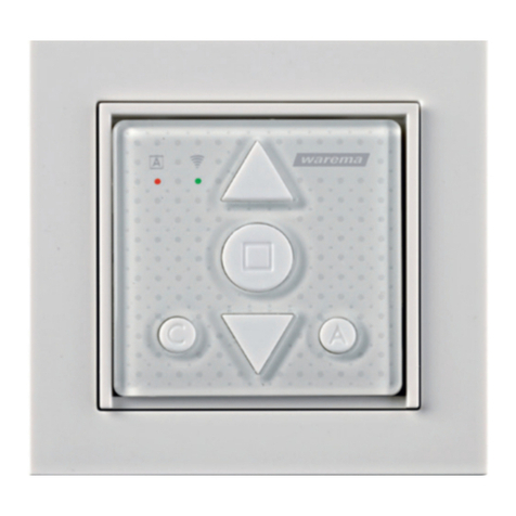
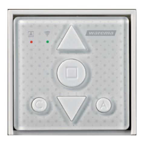
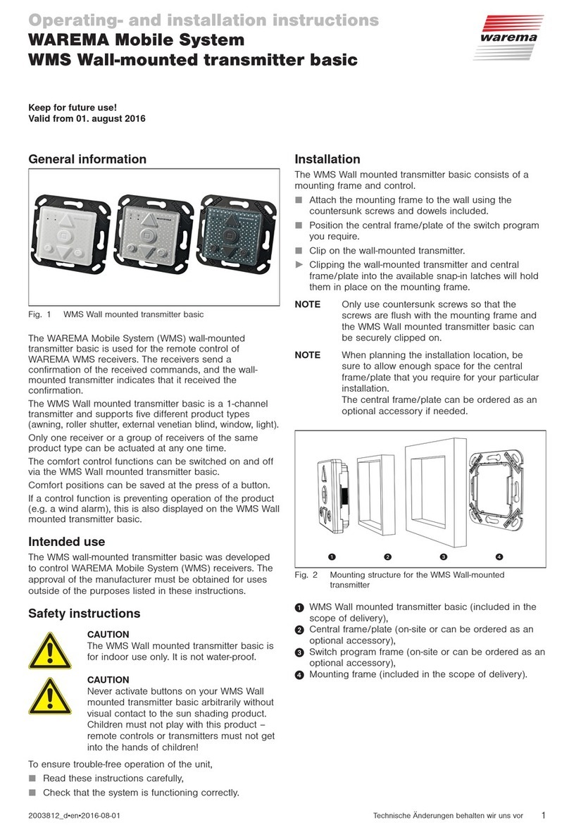
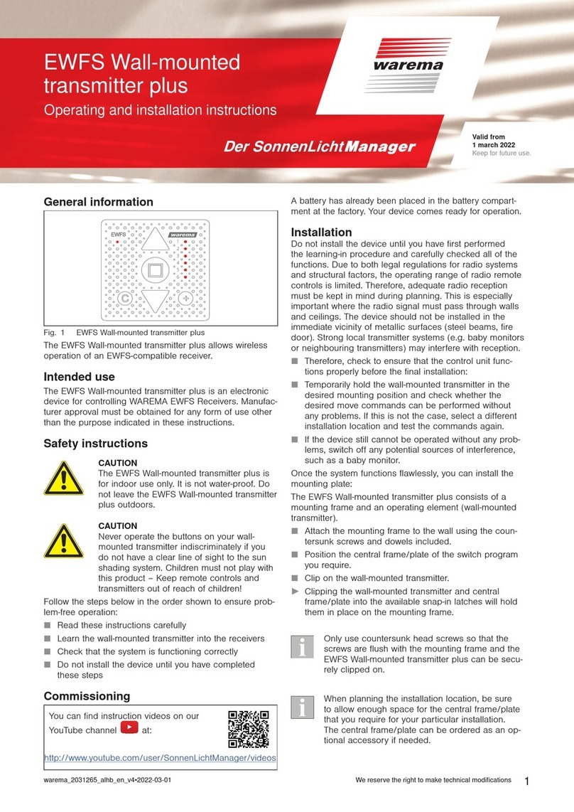
Fig. 1 WMS Wall-mounted transmitter plus
The WMS Wall-mounted transmitter plus is used for
remotely controlling WAREMA WMS receivers for awning,
roller shutter, external venetian blind, window and light
products.
Safety instructions
Intended use
This WMS Wall-mounted transmitter plus is an electronic
device developed to control WMS receivers. Any use other
than the purpose described in these instructions requires
approval from the manufacturer.
AUTIONC
The wall-mounted transmitter plus is for
indoor use only. It is not water-proof. Do
not leave the wall-mounted transmitter plus
outdoors!
AUTIONC
Never activate buttons on your WMS Wall-
mounted transmitter plus arbitrarily without
a line of sight to the sun shading system.
Children must not play with this product –
keep remote controls and transmitters out of
the reach of children!
You can find instruction videos on our
YouTube channel at:
http://www.youtube.com/user/SonnenLichtManager/videos
Learn the WMS Wall-mounted transmitter plus into the
receiver (see also the WMS Practical handbook
art. no. 2031186).
Commissioning can also be carried out using the
WMS studio pro or homee PC software.
Installation
Fig. 2 Mounting structure for the WMS Wall-mounted transmitter
plus
WMS Wall-mounted transmitter plus (included in the
scope of delivery),
Central frame/plate (on-site or can be ordered as an
optional accessory),
Switch program frame (on-site or can be ordered as an
optional accessory),
Mounting frame (included in the scope of delivery).
Attach the mounting frame to the wall using the
countersunk head screws and screw anchors included.
Position the central frame/plate of the switch program
you require.
Clip on the wall-mounted transmitter.
Clipping the wall-mounted transmitter and central
frame/plate into the available snap-in latches will hold
them in place on the mounting frame.
Only use countersunk head screws so that the
screws are flush with the mounting frame and the
WMS Wall-mounted transmitter plus can be secure-
ly clipped on.
Operating and installation instructions
WMS Wall-mounted
transmitter plus
Valid from
1 January 2021
Keep for future use.

warema_2018151_alhb_en_v4•2021-01-01We reserve the right to make technical modifications
2
Operating elements and displays
➊
➌
➍
➐
➎
➑➋
➏
Fig. 3 Operating panel of the WMS Wall-mounted transmitter
plus
+
C
R
2
0
3
2
Fig. 4 Back of the WMS Wall-mounted transmitter plus
Pos. Function Result
Front
AControl button
+
+
Switch the comfort control modes on or off by briefly pressing the
+
and
buttons at the same time (this is the control button on other WMS Hand-held
transmitters).
Comfort button Saving and recalling comfort positions
buttons Send move or switch commands to the selected receiver
Transmission LED
Flashes green = The wall-mounted transmitter plus is transmitting
Flashes red = The wall-mounted transmitter plus has not received a response
from the receiver
Flashes orange: = Change the batteries
Control mode LED
Lights up green = Comfort control modes activated
Lights up red = Comfort control modes deactivated
Flashes red = Operation disabled
Control mode LED and
transmission LED flash
Flashes orange = The wall-mounted transmitter plus has the factory settings
Flashes red =Load factory mode
To leave this mode again, briefly press the Learn button
LED display channel 1 to 6
1
2
3
4
5
6
Selected channel lights up red (here 2)
Change channels button
+
Toggles between channels 1-6
The display skips any unassigned channels and goes to the next assigned channel
(e.g. from channel 1 to channel 3).
Back
Batteries The wall-mounted transmitter plus requires a coin cell CR2032 battery
Learn button Activates or closes learn mode
L LED Lights up green = Learn mode active
Learning in receivers
The first receiver to be learned into the wall-mounted transmitter defines the channel type.
If an external venetian blind is the first receiver to be learned in, the channel type is defined as an external vene-
tian blind channel and only external venetian blinds can be learned in.
To assign a new channel, press the change channel button
+
for 5 s.

3
warema_2018151_alhb_en_v4•2021-01-01 We reserve the right to make technical modifications
Learning in receivers
Wake up
transmitter
Briefly press the stop button Transmission LED lights up
Select
channel
+
Press change channel button, select channel.
1
2
3
4
5
6
Selected channel lights up red (here 2)
Start scan process
5s
Press the L button for approx. 5s
Transmission LED lights up green for 2 s = Target device
(receiver, transmitter or sensor) found, receiver detected, scan
continues
Transmission LED lights up orange for 2 s = no target device
found,
scan complete
Transmission LED lights up red for 2 s = Target device found,
but not yet learnt in, new receiver found
Identify receiver
+
+
Briefly press the buttons
+
+ (= control button)
at the same time
Product waves
Control mode LED flashes green with a receiver for which the
product type can be adjusted.
The type of product displayed depends on the flashing
frequency:
1 x green: Awning 2 x green: Roller shutter
3 x green: External venetian blind 4 x green: Light
5 x green: Window
Set
product type
Briefly press the up or down arrow button
Select receiver / product type
Press Up
Flashing increases by one
Press Down
Flashing decreases by one
Save
allocation
Briefly press the stop button
Transmission LED lights up green for 2s = Confirms the
allocation
Scan process
continues
The scan process is repeated automatically until no
more new devices are found Transmission LED flashes green
Scan stops
Transmission LED lights up orange for 2s
Complete
process
Briefly press the L button Process is completed

warema_2018151_alhb_en_v4•2021-01-01We reserve the right to make technical modifications
4
Operating products
When the button is pressed again while the sun shading product is being lowered, it always moves to 100%
(lower limit position) and the “Position DOWN” value is ignored.
Operating products
Select
channel
+
Press change channel button, select channel.
1
2
3
4
5
6
Selected channel lights up red (here 2)
External venetian blind
Press and briefly hold the up or down arrow button
The external venetian blind moves in the selected direction e.g.
up
Briefly press the up or down arrow button
The external venetian blind turns in the selected direction e.g.
slats tilt up
Press stop button
or keystroke in opposite direction Product stops
Roller shutter
Press the up or down arrow button The roller shutter moves in the selected direction e.g. up
Press stop button
or keystroke in opposite direction Product stops
Awning
Press the up or down arrow button
The awning moves in the selected direction e.g. up
Press stop button
or keystroke in opposite direction Product stops

5
warema_2018151_alhb_en_v4•2021-01-01 We reserve the right to make technical modifications
Operating products
Awning with valance roller blind
Briefly press the up or down arrow button once
The awning moves in the selected direction e.g. up
Press and briefly hold the up or down arrow button
once
The valance roller blind moves in the selected direction e.g. up
Awning position does not change
Briefly press the up arrow button twice
Valance roller blind moves up , then the awning moves up
Briefly press the down arrow button twice
Awning moves down , then the valance roller blind moves
down
Press stop button
or keystroke in opposite direction Product stops
Window
Press the up or down arrow button
Window moves in the selected direction
Press stop button
or keystroke in opposite direction Product stops
Light
Press the up or down arrow button
Light is switched On ( ) or Off ( )
Press stop button
or keystroke in opposite direction
Switch product
(ON→OFF, OFF→ON)

warema_2018151_alhb_en_v4•2021-01-01We reserve the right to make technical modifications
6
Comfort position
If a product is already in the comfort position or if a comfort position has not been stored, the selected product
does not respond when the comfort button is pressed.
If the unit does not move to the comfort position correctly, the run time in the receiver has to be adjusted.
Comfort position
Learn
Press the up or down arrow button
Move to desired position (in this case, e.g. external venetian
blind up)
5s
Press the comfort button for 5 s
Transmission LED lights up green for 2s = Comfort position
saved
Transmission LED lights up red for 2s = Command not
confirmed
Repeat process
Move
Press the comfort button briefly
The unit moves to the comfort position (e.g. up)
Comfort control modes
Channel
selection
+
Press change channel button, select channel.
1
2
3
4
5
6
Selected channel lights up red (here 2)
Switch on / off
+
+
Briefly press the buttons
+
+ (= control but-
ton) at the same time
The control mode LED lights up green = Control modes On
The control mode LED lights up red = Control modes Off

7
warema_2018151_alhb_en_v4•2021-01-01 We reserve the right to make technical modifications
Deleting learned-in products from the WMS wall-mounted transmitter plus and the
network
Devices that do not need to be deleted must be de-energised.
If you delete a receiver from the network, it can no longer be operated via other transmitters. It must be learned
into a network again.
Deleting receivers
Wake up
wall-mounted transmitter
Briefly press the stop button
Transmission LED lights up
Select
channel
+
Press change channel button, select channel.
1
2
3
4
5
6
Selected channel lights up red (here 2)
Start
scan process
5s
Press the L button for approx. 5s
or
Transmission LED lights up permanently (orange or red) = Scan
is complete
Send
delete command
+
Briefly press the stop and C buttons at the same
time Product waves = Delete command carried out
Resend
delete command
Repeatedly press the stop button until all products to be deleted have waved.
Complete
process
Briefly press the L button Process is completed

warema_2018151_alhb_en_v4•2021-01-01We reserve the right to make technical modifications
8
Maintenance
Dismantling
To remove the WMS Wall-mounted transmitter plus (e.g.
to replace the battery), carefully pull the clipped wall-
mounted transmitter off the frame.
Hold onto the central frame/plate, as it comes loose
when the wall-mounted transmitter is removed.
Replacing the battery
Remove the old battery from the compartment by
carefully sliding a screwdriver (slotted, 2 - 3 mm) at the
notch in the housing below the edge of the battery and
prising the battery out.
When inserting the new battery, make sure that the
polarity matches: the positive terminal (+) of the battery
should face up (visible) and the negative terminal (-)
should face down.
Only touch the battery at the edge.
When inserting the battery, be sure to push it below
the gold clasp first (see Fig. 6).
Use a high-grade battery – inexpensive batteries may
leak and damage the device. If you do not intend to
use the device for an extended period of time, please
remove the battery.
Fig. 5 Removing the battery
Fig. 6 Inserting the new battery
To spare the coin cell of the WMS Wall-mounted
transmitter plus during the learning process, the
waking time of the WMS Wall-mounted transmitter
plus has been reduced to 1minute. If your device
stops responding, simply wake it up by pressing
the Stop button, for example
Cleaning
Clean the housing with a soft, damp cloth. Do not use
detergents, cleaning agents, solvents, abrasive substances
or steam cleaners!
Liability
The liability for consequential damage to persons or
property is excluded if the device is used for any purpose
other than those described in these instructions. Observe
the information in the operating instructions for your sun
shading system. Liability is also excluded for damage to
the sun shading system resulting from operation under icy
conditions.
Disposal
After use, the device and the batteries must be disposed
of according to legal regulations or brought to your local
recycling centre.
Technical data
WMS Wall-mounted
transmitter plus min. typ. max. Unit
Supply
Battery type 1 x coin cell CR 2032
Operating voltage 1.8 3.0 3.2 V DC
RF transceiver
Transmission frequency 2.40 2.48 GHz
Transmission power 0 dBm
Reception sensitivity -101 dBm
Operating range
(environment without
interference)
30 m
Housing
WMS Wall-mounted
transmitter plus
(L×W×H in mm)
50 × 50 × 10.5
Mounting frame
(L×W×H in mm)
70 × 70 × 5
Degree of protection IP30
Safety class III
Miscellaneous
Conformity
Available at www.warema.de/ce
This device complies with the EMC directives for use in
residential and commercial areas.
WAREMA Renkhoff SE declares herewith that this radio
system type [WMS Wall-mounted transmitter plus] is in
compliance with the current guidelines.
Ambient conditions
Operating temperature 0 50 °C
Storage temperature 0 70 °C
Humidity
(non-condensing)
10 40 85 %Hrel
Degree of soiling 2
article numbers
WMS Wall-mounted transmitter
plus, white
(6 channel)
2016 193
Optional accessories
White frame* 2004 341
* consisting of a central frame/plate and switch program frame
WAREMA Renkhoff SE
Hans-Wilhelm-Renkhoff-Strasse 2
97828 Marktheidenfeld
Germany
Table of contents
Other WAREMA Transmitter manuals

WAREMA
WAREMA WMS User manual

WAREMA
WAREMA EWFS User manual

WAREMA
WAREMA EWFS User manual

WAREMA
WAREMA WMS User manual

WAREMA
WAREMA EWFS Wall-mounted transmitter plus User manual

WAREMA
WAREMA WMS User manual

WAREMA
WAREMA WMS Hand-held transmitter comfort User manual

WAREMA
WAREMA WMS User manual

WAREMA
WAREMA WMS Wall-mounted transmitter plus User manual

WAREMA
WAREMA WMS User manual