WAREMA EWFS User manual

Operating and installation instructions
EWFS Wall-mounted transmitter basic
Keep for future use!
Valid from 1 august 2019
2031261_0•en•2019-08-01 We reserve the right to make technical changes 1
General information
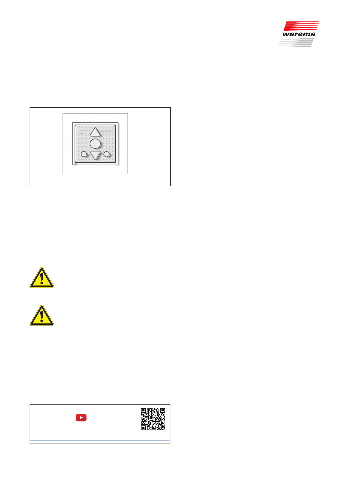
Fig. 1 EWFS Wall-mounted transmitter basic
The EWFS Wall-mounted transmitter basic allows wireless
operation of an EWFS-compatible receiver.
Intended use
The EWFS Wall-mounted transmitter basic is an electronic
device for WAREMA EWFS Receivers. Manufacturer ap-
proval must be obtained for any form of use other than the
purpose indicated in these instructions.
Safety instructions
AUTIONC
The EWFS Wall-mounted transmitter basic is
for indoor use only. It is not water-proof. Do
not leave the EWFS Wall-mounted transmitter
basic outdoors.
AUTIONC
Never operate the buttons on your wall-
mounted transmitter indiscriminately if you
do not have a clear line of sight to the sun
shading system. Children must not play with
this product – Keep remote controls and
transmitters out of reach of children!
Follow the steps below in the order shown to ensure prob-
lem-free operation:
Read these instructions carefully
Learn the EWFS wall-mounted transmitter basic into the
receivers
Check that the system is functioning correctly
Commissioning
You can find instruction videos on our
YouTube channel at:
http://www.youtube.com/user/SonnenLichtManager/videos
A battery has already been placed in the battery compart-
ment at the factory. Your device comes ready for operation.
Installation
Do not install the device until you have first performed
the learning-in procedure and carefully checked all of the
functions. Due to both legal regulations for radio systems
and structural factors, the operating range of radio remote
controls is limited. Therefore, adequate radio reception
must be kept in mind during planning. This is especially
important where the radio signal must pass through walls
and ceilings. The device should not be installed in the
immediate vicinity of metallic surfaces (steel beams, fire
door). Strong local transmitter systems (e.g. baby monitors
or neighbouring transmitters) may interfere with reception.
Therefore, check to ensure that the control unit func-
tions properly before the final installation:
Temporarily hold the wall-mounted transmitter in the
desired mounting position and check whether the
desired move commands can be performed without
any problems. If this is not the case, select a different
installation location and test the commands again.
If the device still cannot be operated without any prob-
lems, switch off any potential sources of interference,
such as a baby monitor.
Once the system functions flawlessly, you can install the
mounting plate:
The EWFS Wall-mounted transmitter basic consists of a
mounting frame and an operating element (wall-mounted
transmitter).
Attach the mounting frame to the wall using the coun-
tersunk screws and dowels included.
Position the central frame/plate of the switch program
you require.
Clip on the EWFS Wall-mounted transmitter basic.
Clipping the EWFS wall-mounted transmitter basic and
central frame/plate into the available snap-in latches
will hold them in place on the mounting frame.
OTICEN Only use countersunk head screws so that the
screws are flush with the mounting frame and
the EWFS Wall-mounted transmitter basic can
be securely clipped on.
OTICEN When planning the installation location, be sure
to allow enough space for the central frame/
plate that you require for your particular instal-
lation.
The central frame/plate can be ordered as an
optional accessory if needed.

2031261_0•en•2019-08-01We reserve the right to make technical changes
2
Fig. 2 Mounting structure for the EWFS Wall-mounted transmit-
ter basic
EWFS Wall-mounted transmitter basic (included in the
scope of delivery),
Central frame/plate (on-site or can be ordered as an
optional accessory),
Switch program frame (on-site or can be ordered as an
optional accessory),
Mounting frame (included in the scope of delivery).
Back operating elements
C
R
2
0
3
2
ON OFF
12 345
Fig. 3 Back of EWFS Wall-mounted transmitter basic
Pos. Fig. Function
Mode button
Learn button
Activates or closes the learn mode of the EWFS
Wall-mounted transmitter basic
Batteries
The EWFS Wall-mounted transmitter basic requires
a coin cell CR2032 battery.
Store button
Used to save wind or brightness limit values, de-
pending on the receiver's range of functions.
5Sliding switch
Switches the sun control off permanently ("ON" /
"OFF").
Front operating elements
EWFS
EWFS
1
2
3
4
5
6
Fig. 4 EWFS Wall-mounted transmitter basic
Pos. Fig. Function EWFS Wall-mounted transmitter basic
Transmission LED lights up red:
The EWFS Wall-mounted transmitter basic is
transmitting.
②UP Button
Raises the sun shading system
③STOP Button
Stops a move command
(or pressing the button of the opposite direction)
④DOWN Button
Lowers the sun shading system.
Comfort button
This button can be used to store and call up
comfort positions.
Button "Automatic" ON/OFF
Press the button briefly
This switches the comfort control funkctions of all
learned in receivers on or off.

3
2031261_0•en•2019-08-01 We reserve the right to make technical changes
Operation
OTICEN A receiver and connected sun shading system
cannot be operated until a transmitter has been
learned in successfully.
Operating the EWFS Wall-mounted transmitter basic:
After the "Up" or "Down" button has been pressed, the
transmission LED lights up briefly and the sun shad-
ing system moves in the corresponding direction. The
system can be stopped by pressing either the other
directional button or the stop button.
Switching sun control on or off
The sun control automatic mode can be switched on or off
permanently using the sliding switch (see Fig. 3).
After inserting the battery, use a pointed object (pa-
perclip, ballpoint pen) to slide the switch to the "OFF"
position (see Fig. 3).
Press and hold the "S" button. The LED on the front
briefly lights up red, and the move command is sent.
Release the button again when the sun shading sys-
tem waves.
Sun control is now permanently switched off.
Symbols used
When the receiver is delivered, it does not "know" any
transmitters initially and therefore must first learn which
transmitters it should respond to. We refer to this process
as "learning-in".
Explanation of symbols:
Power-up: In order to learn in a transmitter, you
must de-energise a receiver or a group of receiv-
ers, either at the upstream in-line circuit breaker
or at the corresponding plug-in connector, and
then energise it again after approx. 5 seconds.
(Power-up procedure.) Always perform a power-up
procedure when you see the in-line circuit breaker
symbol.
Here, the receiver is in the learn mode for approx.
one minute. The learn button on the transmitter
must be pressed during this time interval or the
receiver will exit the learn mode. Press the learn
button on your transmitter whenever you see the
learn button symbol.
Wave: After you press the learn button on the
transmitter, the connected sun shading system
carries out several movements in a waving motion.
In these instructions, we use the adjacent symbol
to denote waving. Single wave: Press the learn
button on the transmitter, wait until the connected
sun shading system moves, and then release the
button immediately.
Learning in a master channel
In this section, a channel will be learned into a receiver
(shown using the example of an EWFS Plug receiver).
When you perform a power-up procedure on the receiver,
the receiver learns in the first channel it receives as the
master channel:
= Master channel
?
Fig. 5 The receiver does not "know" any channels yet (left).
A new channel is learned in and becomes the master
channel (right).
Perform the steps below in the order shown:
Put receiver in learn
mode: Perform the pow-
er-up procedure on the
receiver.
Learn in master channel:
On the wall-mounted
transmitter, press and
hold the learn button.
When the sun shading
system waves once, re-
lease the button.
Receiver automatically
exits learn mode. The
wall-mounted transmitter
is now the master channel
on the receiver.
Result: The receiver now knows a master channel.
OTICENAll channels learned into the receiver after the
first channel are learned as auxiliary channels. If
the receiver already knows a master channel, the
power must not be cut off to enter the learn mode
again for the auxiliary channels, since this master
channel must be used to start the learn mode.

2031261_0•en•2019-08-01We reserve the right to make technical changes
4
Learning in an auxiliary channel
Now an auxiliary channel will also be learned into the
receiver. Auxiliary channels can be used for the following
purposes:
To allow multiple people to operate the sun shading
system with their own wall-mounted or hand-held trans-
mitters.
To enable operation of the sun shading system using
different transmitters, e.g. manual operation with a
wall-mounted or hand-held transmitter, automatic con-
trol mode with a time switch.
An important feature of auxiliary channels is that they
can be used to build groups.
1
ΙΙ
Ι
= Master channel = Auxiliary channel
Fig. 6 Operating a receiver with a master channel (I) and
auxiliary channel (II). To enter the learn mode, use the
wall-mounted or hand-held transmitter on the master
channel.
Perform the steps below in the order shown:
Put receiver in learn
mode: On the wall-mount-
ed or hand-held transmit-
ter that was just used to
learn in the master chan-
nel (I), press and hold the
learn button. When the
sun shading system
waves once, release the
button.
Learn in wall-mounted
transmitter (II) as an aux-
iliary channel: Using the
wall-mounted transmitter
(II), press and hold the
learn button. When the
sun shading system
waves once, release the
button.
Exit learn mode: Using the
wall-mounted or hand-held
transmitter on the master
channel (I), press the UP
or DOWN button. When
the sun shading system
moves, the learn mode is
no longer active.
Result: The sun shading system can now be operated
using both wall-mounted transmitters (or one
wall-mounted and one hand-held transmitter.
The wall-mounted transmitter (II) is the auxiliary
channel.
Ι
ΙΙ
Ι
OTICEN Only the receiver is capable of learning, not the
transmitter. Learning in auxiliary channels is the
first step to building groups. When you wish to
learn in an auxiliary channel, do not perform
the power-up procedure, as you will need to
start the learn mode using the master channel.
OTICENAn auxiliary channel can be a 1-channel trans-
mitter, one channel of an 8-channel transmitter, a
channel of the EWFS Timer or a weather station.
OTICENIMPORTANT! A receiver can manage one
master channel and up to 15 additional auxiliary
channels, for a total of 16 different channels.
Any attempt to learn in a greater number of
channels will fail.
OTICEN For learning transmitters into other products,
as well as additional information on the topic
of learning-in, please refer to the operating and
installation instructions for the receivers.

5
2031261_0•en•2019-08-01 We reserve the right to make technical changes
Maintenance
Replacing the batteries
When inserting the new battery, make sure that the po-
larity matches (see Fig. 3 on page 2: the positive
terminal (+) of the battery should face up (visible) and
the negative terminal (-) should face down (see Fig. 3).
Only touch the battery on its edge.
When inserting the batteries, make sure that they are
pushed to one side under the contacts.
Use a high-quality battery – inexpensive batteries may
leak and damage the device. If the device will be out of
use for an extended period of time, remove the battery.
Dismantling
To remove the wall-mounted transmitter (e.g. to replace
the battery), carefully pull the clipped wall-mounted
transmitter off of the frame.
Hold onto the central frame/plate as it comes loose
automatically when the wall-mounted transmitter is
removed.
Liability
In the event of the failure to comply with the product
information contained in these instructions, or if the
device is used in any manner other than its designated
or intended use, the manufacturer may refuse to honour
warranty claims for product damage. In this case, liability
for consequential damage to persons or property will also
be excluded. In addition, be sure to observe the informa-
tion contained in the operating instructions for your sun
shading system. Automatic or manual operation of the sun
shading system while it is iced over or the use of the sun
shading system during severe weather may cause dam-
age, which the user is responsible for preventing by taking
suitable precautions.
Disposal
After use, the device and the batteries must be disposed
off in accordance with legal regulations or returned to your
local recycling centre.
Technical data
EWFS Wall-mounted
transmitter basic Min. Typ. Max. Unit
Supply
Battery type 1 x coin cell CR 2032
Operating voltage 2.1 3 3.1 V DC
Battery durability 2 years
Current consumption,
active 16 mA
RF transmitter
Transmission frequency 433.92 MHz
Transmission power 10 dBm
Operating range
(environment w/o interfer-
ence)
30 m
Enclosure
Dimensions in mm
(WxHxD) 50 x 50 x 10
Degree of protection IP30
Safety class III
Miscellaneous
Conformity available at www.warema.de/ce
This device meets the requirements on electromagnetic immu-
nity and electromagnetic interference for use in residential and
commercial environments.
WAREMA Renkhoff SE declares herewith that this radio system
type [EWFS Wall-mounted transmitter basic] is in compliance
with the current guidelines.
Ambient conditions
Operating temperature 0 20 70 °C
Storage temperature -25 70 °C
Humidity
(not condensing) 10 40 85 %RH
Degree of soiling 2
Article numbers
EWFS Wall-mounted trans-
mitter basic 2031 244
Optional accessories
Frame for EWFS / WMS
Wall-mounted transmitter,
white
(consisting of a central
frame/plate and switch
program frame)
2004 341
WAREMA Renkhoff SE
Hans-Wilhelm-Renkhoff-Strasse 2
97828 Marktheidenfeld
Germany

2031261_0•en•2019-08-01We reserve the right to make technical changes
6
Troubleshooting
EWFS Wall-mounted transmitter basic Help with malfunctions
Type of malfunction Possible cause Remedy
Transmission LED does not light up Battery inserted with wrong polarity or
depleted
Insert batteries correctly; insert new
batteries
Transmission LED lights up, but move com-
mand is not carried out
Wall-mounted transmitter has not been
learned into the receiver
Learn in the transmitter as described in the
receiver instructions
Interfering ambient influences Reduce the distance between the transmit-
ter and receiver
Receiver is not supplied with mains voltage Switch on the power supply
Switch commands are only carried out
sporadically
Interference caused by an outside trans-
mitter
Deactivate the outside transmitter
(e.g. baby monitor)
Rechargeable batteries were inserted in
the device
Do not use rechargeable batteries; use
only high-quality coin cell batteries (type
CR 2032)
Too much distance between transmitter
and receiver
Reduce the distance to the receiver
Reinforced concrete ceilings or walls are lo-
cated between the transmitter and receiver
Reduce the distance to the receiver or
choose a different installation location
Table of contents
Other WAREMA Transmitter manuals

WAREMA
WAREMA WMS User manual

WAREMA
WAREMA WMS User manual

WAREMA
WAREMA WMS Hand-held transmitter comfort User manual

WAREMA
WAREMA WMS User manual

WAREMA
WAREMA EWFS User manual

WAREMA
WAREMA WMS User manual

WAREMA
WAREMA WMS User manual

WAREMA
WAREMA EWFS Wall-mounted transmitter plus User manual

WAREMA
WAREMA WMS Wall-mounted transmitter plus User manual

WAREMA
WAREMA WMS plus User manual
Popular Transmitter manuals by other brands

Novus
Novus TxRail Installation and operating manual

AMG
AMG AMG4783R-SF-CWDMn-C instruction manual

Kramer
Kramer SID-X3N user manual

Status Instruments
Status Instruments SEM210X User instruction

GALAXIS SHOWTECHNIK
GALAXIS SHOWTECHNIK PYROTEC PFS Pocket user manual

Multi-code
Multi-code 4140 installation instructions