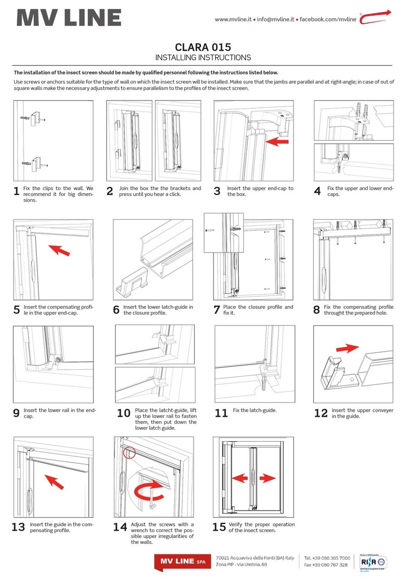
WAREMA External venetian blind User manual

WAREMA external venetian blind
with auxiliary motor and battery-operated
emergency retraction set
cable guidance
Installation instructions
For qualified technicians only
Valid from 22 June 2012
Document no. [M2001452_0] – EN

Table of contents
[M2001452_0] - EN / 22.06.12 Page 2 of 20 Subject to change without notice
Table of contents
1Introduction ....................................................................................................................... 3
1.1Information on safety....................................................................................................................................... 3
1.2Explanation of symbols and signs ................................................................................................................... 3
1.3Important safety information............................................................................................................................ 4
1.4Information on the target group and application of these instructions.............................................................. 5
2Product information ........................................................................................................... 6
2.1Parts description.............................................................................................................................................. 6
2.2Technical data/accessories ............................................................................................................................. 6
2.3Intended use.................................................................................................................................................... 7
2.4Wind speed limits ............................................................................................................................................ 8
2.5CE conformity.................................................................................................................................................. 8
3Installation ......................................................................................................................... 9
3.1Tools ............................................................................................................................................................... 9
3.2Unpacking the external venetian blind........................................................................................................... 10
3.3Scope of delivery........................................................................................................................................... 10
3.4Marking the position of the external venetian blind........................................................................................ 10
3.5Mounting the bracket/top rail bracket ............................................................................................................ 11
3.6Preparing the feedthrough for the power line ................................................................................................ 13
3.7Attaching and centring the top rail ................................................................................................................. 14
3.8Securing the top rail ...................................................................................................................................... 14
3.9Overview of the fixation possibilities of the tension cable (optional).............................................................. 15
3.10Attaching the tension cable using the tension cable bracket/tension cable holder ........................................ 15
3.11Attaching the tension cable with the plastic spring tension device ................................................................ 17
3.12Performing a functional check with the external venetian blind ..................................................................... 18
3.13Final tasks ..................................................................................................................................................... 19

Introduction
[M2001452_0] - EN / 22.06.12 Page 3 of 20 Subject to change without notice
1 Introduction
1.1 Information on safety
It is important to follow these instructions in the inte-
rests of personal safety. Failure to comply with these
instructions when operating the product may result in
personal injury and/or property damage. Failure to
comply with these instructions relieves WAREMA of liabili-
ty.
Warnings are marked with these symbols in
the instructions.
Read the instructions carefully before
starting with the installation.
Read and observe all warnings.
Please observe all safety, installation,
operating and setting instructions.
Observe all warnings on the product.
1.2 Explanation of symbols and signs
Safety information and symbols are contained in the ap-
propriate parts of the text.
Symbol Use/explanation
DANGER
Identifies an imminent danger that may
result in death or serious injury if not pre-
vented.
WARNING
Identifies a potential danger that may result
in death or serious injury if not prevented.
CAUTION
Identifies a potential danger that may result
in minor injury or property damage if not
prevented.
Read the installation instructions.
)
Note
Important information on how to proceed
and on the content of these instructions.
Activity/step
`
List

Introduction
[M2001452_0] - EN / 22.06.12 Page 4 of 20 Subject to change without notice
1.3 Important safety information
The safety instructions and warnings described here are
intended to safeguard your health as well as protect the
product. Please read the following points carefully.
Damage resulting from inappropriate use or the failure to
observe these instructions or safety information is not
covered by the guarantee. Liability will not be accepted
for secondary damage.
General conditions
If the external venetian blind with auxiliary motor and bat-
tery-operated emergency retraction set is used at escape
doors and emergency windows to protect against sum-
mer heat and glare and to provide privacy, the battery-
operated emergency retraction set is activated in case of
an emergency to clear the escape route.
Correct functioning of the external veneti-
an blind with auxiliary motor and battery-
operated emergency retraction set and,
therefore, unblocking of the escape doors
and emergency windows in case of an
emergency are only ensured if you follow
our safety instructions closely.
Danger to life and limb if the WAREMA
control is not used!
It must be ensured that the external venetian
blind is only activated by the associated
electronic battery-operated control. Mani-
pulations by third parties must be
excluded. It is important that the external
venetian blind is not blocked by dirt or
obstacles.
Danger to life and product damage from
incorrect procedure during commission-
ing! If the following points are not followed,
no warranty can be granted for functional
problems, soiling and damage.
The external venetian blind must remain
out of service until the commissioning has
been released.
Raise the external venetian blind fully to
clear the escape route. The external ve-
netian blind is sufficiently raised if the ex-
ternal venetian blind disappears into the
cover panel (if present), or if the escape
door or emergency window can be ope-
ned.
Installation preparations
Danger to life from restrictions of the escape
route while during installation of the external
venetian blind with auxiliary motor and bat-
tery-operated emergency retraction set! Befo-
re beginning installation, inform the safety
officer that the escape route is available only
to a limited extent. It must be ensured that the
building can be evacuated along a different
escape route.
Risk of injury and damage to the product
from incorrect installation!
Comply with the specified installation
steps and instructions.
Install the product only if it is in technically
perfect condition.
Before installation, check the mounting
substructure to make sure it can bear the
loads.
Widely cordon off the installation site and
the projection area of the external veneti-
an blind.
Packaging
Risk of suffocation! Do not leave the packa-
ging material lying around, and keep children
away from small parts. Plastic film, polystyre-
ne, small parts, etc., can be very dangerous
for children to play with.
Electrical connection
Electric shock from incorrect installation!
The electrical installation must be performed
by a certified electrician in accordance with
the electrical installation regulations published
by the Association of German Electrical Engi-
neers (VDE 0100) or the standards and regu-
lations of the country in which the product is
being installed. The specialist must observe
the installation instructions included with the
electrical appliances. Before commissioning
the product, remove all lines that are not re-
quired. Disconnect any devices that are not
needed for operation.


Introduction
[M2001452_0] - EN / 22.06.12 Page 5 of 20 Subject to change without notice
Risks posed by the product
Risk of crushing and injury! When raising
and lowering the product and when making
the electrical connection of the system, do not
reach into movable parts (e.g. between the
bottom rails and/or slats).
Risk of damage to the product
Risk of injury from unmonitored or impro-
per operation of the external venetian
blind. Install the operating elements of the
product and the emergency push button of the
external venetian blind with auxiliary motor
and battery-operated emergency retraction
set outside of the projection area but within
view of the product at a height that meets the
national regulations for the disabled. Instruct
customers on how to use the product.
Product damage and property damage
from carelessness during operation! The
projection area of the external venetian blind
must be kept clear of fixed and movable
obstacles.
Transport
Risk of injury and product damage from
inappropriate transport! The gross axle
weight rating and gross weight rating of the
transport vehicle must not be exceeded. A
loaded vehicle may handle differently.
Secure the transported goods appropriately and safely.
Protect the packaging of the product against moisture.
Soaked packaging may work loose and cause accidents.
1.4 Information on the target group and ap-
plication of these instructions
Target group
These installation instructions are intended for quali-
fied fitters. Knowledge of safety at work, accident pre-
vention regulations, working with ladders and scaffolding,
handling and transporting long and heavy items, using
fixation materials, assessment of the building fabric,
commissioning and operation of the product is required. If
any of these qualifications are unavailable, the work must
be carried out by a specialist fitting company.
The electrical installation must be performed by a certified
electrician in accordance with the electrical installation
regulations published by the Association of German
Electrical Engineers (VDE 0100) or the standards and
regulations of the country in which the product is being
installed.
Contents
These instructions are part of the operating manual and
are an integral part of this product. These instructions
contain important information on transport, handling, in-
stallation and commissioning of this item. They describe
the basic installation of the WAREMA external venetian
blind with auxiliary motor and battery-operated emergency
retraction set and rail guidance. Other versions or special
solutions are not dealt with.
Permissible activities
Aside from the activities described for the product in these
installation instructions, alterations, additions and mainte-
nance work on the product are not permitted without the
written approval of WAREMA.

Product information
[M2001452_0] - EN / 22.06.12 Page 6 of 20 Subject to change without notice
2 Product information
2.1 Parts description
dd200005240
1 Top rail 6 Bottom rail
2 External venetian blind
drive (motor)
7Tilting tape
3 Auxiliary motor 8 Emergency push but-
ton*
4 Tension cable 9 Battery-operated con-
trol*
5 Slat 10 Lifting tape
Fig. 1: Parts overview for the external venetian blind with
auxiliary motor and battery-operated emergency re-
traction set and cable guidance
* The emergency push button and the battery-
operated control together make up the emergency
retraction set
2.2 Technical data/accessories
Weight Value
Flat slat Approx. 2.7 kg/m²
Beaded slat Approx. 3.1 kg/m²
Dim-out slat Approx. 3.2 kg/m²
Tab. 1: Weights for external venetian blind
Data for electric drive (external venetian blind drive)
Parameter D339
Rated torque 9 Nm
Power 131 W
Current consumption 0.57 A
Rated speed 26 rpm
Rated voltage 230 V AC
Frequency 50 Hz
Degree of protection IP 54
Short-term operation (S2) 4 minutes
Limit switch range 97 revolutions
Tab. 2: Details on the external venetian blind drive
)NOTE
The technical data on the control can be found in
the associated installation instructions.
Accessories
A wide range of control devices is available for the sun
shading system to give you optimum control of the pro-
duct. These controls can be combined with the
emergency retraction system. However, this must be
clarified on a case by case basis.
Do not use the external venetian blinds in icy or frosty
weather. Liability cannot be accepted for damage to the
sun shading system resulting from the operation under icy
conditions. We recommend using an ice monitoring sys-
tem.

Product information
[M2001452_0] - EN / 22.06.12 Page 7 of 20 Subject to change without notice
2.3 Intended use
The external venetian blind with auxiliary motor and bat-
tery-operated emergency retraction set is an external sun
shading system used at escape doors and emergency
windows to protect against summer heat and glare and to
provide privacy. In the projection area of the external
venetian blind, there must be no obstacles/protruding
parts (for example, door stop), especially on the door
leaf, that would prevent raising of the external veneti-
an blind while also opening the escape door at the
same time. If this cannot be prevented, other technical
measures must ensure that the closure on the door leaf
can be opened before the escape route is cleared by the
external venetian blind with auxiliary motor and battery-
operated emergency retraction set. However, this must
always be planned and approved by the architect/planner
or the local building authority. Inappropriate use may
result in significant danger.
All external venetian blinds for external use are designed
for a wind load of 1.1 kN/m² (DIN 1055). The directive
entitled "Wind loads for construction of closures and aw-
nings when retracted – Section 5.1.1"1defines the positi-
ons at which these products can be installed without
requiring special precautions.
To ensure that the external venetian blind with auxiliary
motor and battery-operated emergency retraction set can
be activated reliably, the external venetian blind must
always be operated via the associated electronic bat-
tery-operated control.
Additional loads on the external venetian blind with auxili-
ary motor and battery-operated emergency retraction set,
such as from suspended objects, could damage the pro-
duct or cause it to fall (for example, tearing of the lifting
tapes), or cause the external venetian blind with auxiliary
motor and battery-operated emergency retraction set to
fail, and are therefore also not permitted.
The intended use also includes observing these instruc-
tions and the installation conditions.
1Published by the Bundesverband Rollladen + Son-
nenschutz e.V. and Bundesverband Konfektion
Technischer Textilien e.V. - BKTex
)NOTE
Compliance with legal provisions and country-
specific regulations on site is the responsibility of
the ordering party/building owner. There may be
regional regulations and conditions that prohibit
use of the external venetian blind with auxiliary
motor and battery-operated emergency retraction
set. However, each and every case cannot be
investigated by WAREMA.
)NOTE
Use of the battery-operated control for external
venetian blinds with auxiliary motor and battery-
operated emergency retraction set is only permis-
sible in normal room climates. The intended use
only applies in the specified temperature range (as
per the technical data in the installation instruc-
tions). Use in damp locations (such as swimming
pools) is not permissible.
The heating from outside influences must be less
than the intrinsic warmth.

Product information
[M2001452_0] - EN / 22.06.12 Page 8 of 20 Subject to change without notice
2.4 Wind speed limits
For external venetian blinds, the use of wind speed limits
(see Tab. 3) depends on the particular product type. If the
wind speed limits are reached, the external venetian blind
must be retracted. It is recommended that the wind sen-
sors be set to the lowest value, e.g. to 13.5 m/s for Beau-
fort 7.
Basis of Table 3:
Slat facade distance: ≤ 100 mm
Slat thickness: ≥ 0.4 mm
Order height: < 2400 mm
Order width Beaded slat with
cable guidance
Flat slat with cable
guidance
Width up to
1500 mm
13.5 – 17.4 m/s
(7 Bft.)
13.5 – 17.4 m/s
(7 Bft.)
Width up to
2000 mm
13.5 – 17.4 m/s
(7 Bft.)
10.5 – 13.4 m/s
(6 Bft.)
Width up to
2500 mm
10.5 – 13.4 m/s
(6 Bft.)
10.5 – 13.4 m/s
(6 Bft.)
Width up to
3000 mm
10.5 – 13.4 m/s
(6 Bft.)
10.5 – 13.4 m/s
(6 Bft.)
Width up to
3500 mm
10.5 – 13.4 m/s
(6 Bft.)
7.5 – 10.4 m/s
(5 Bft.)
Tab. 3: Recommended wind speed limits (details in m/s
and Beaufort number)
The table values (Beaufort number) should be modified in
the following cases:
1. Facade distance
> 100 to 300 mm: Reduce value by 1
> 300 to 500 mm: Reduce value by 2
> 500 mm: Table not applicable
2. Material thickness
< 0.4 mm: Reduce value by 1
3. Height-dependent with cable guidance
2400 to 4000 mm: Reduce value by 1
The external venetian blinds will only meet the require-
ments of the stated wind speed limits when mounted if:
the recommended number of brackets, holders and
guides are mounted
the instructions from the manufacturers for the dowels
are followed
When mounting on wood, a wind speed limit cannot be
given due to the variability of this building material.
2.5 CE conformity
CE conformity is certified, and the corresponding EC dec-
laration of conformity is part of these product-specific
operating and maintenance instructions. To maintain this
state and to ensure that the product can be safely instal-
led and commissioned, you must adhere to the installation
instructions.
The CE declaration of conformity of the battery-operated
control is contained in the separate installation instruc-
tions.
Name: WAREMA Renkhoff SE
Year of declaration of conformity: 2011
Head
office:
Hans-Wilhelm-Renkhoff-Straße 2
97828 Marktheidenfeld
Germany
Standard: DIN EN 13659
Product: External venetian blinds
Intended use For outdoor installation
Wind class: 0
2
Noise emission level: < 70 dB (A)
3
2
Specification of wind class 0, since standard test
stands cannot be used in the applicable test stan-
dard due to mechanical inadequacies of the test
description. Depending on the model and the instal-
lation location, the product can be used up to the
wind speed limit specified above (see Tab. 3).
3
In a standard installation of the product on a test
stand, the noise emission level is <70 dB(A). This
value may vary depending on the installation.

Installation
[M2001452_0] - EN / 22.06.12 Page 9 of 20 Subject to change without notice
3 Installation
)NOTE
The installation tasks may only be performed by a
qualified specialist (for example, roller shutter and
venetian blind builder/roller shutter and sun sha-
ding system mechatronics technician); this means
that the authorised qualified specialist described
below must have these special qualifications.
)NOTE
The method of installation depends on the particu-
lar installation situation.
Installation into a cover panel
Installation of the top rail bracket directly on
the mounting substructure
The following installation steps are not contained
in these installation instructions and are described
in the installation instructions that accompany the
respective product.
Installation of the cover panel.
CAUTION
Product damage and malfunctions from incor-
rect installation!
In case of a later installation of the cover
panel, the top rail must be protected from
penetrating water.
At least two people are required for the instal-
lation.
)NOTE
Application drawings must be followed.
WARNING
Risk of injury and falling!
Climbing aids must be positioned securely,
provide enough support and have a suffi-
ciently high load-bearing capacity.
When working at great heights, the approp-
riate provisions must be made to protect
against falling.
Under no circumstances should persons
use the external venetian blind as a means
of support.
3.1 Tools
Tool/aid Size Use
Tape mea-
sure/spirit level
Pencil/pointed ob-
ject
Pencilling in of fixing
points
Power drill Fixing holes
Drill bits (collection) Drilled holes (depen-
ding on substructure)
Drill bits (depending
on the substruc-
ture)
10 Power line
feedthrough
Drill bits (depending
on the substructure)
20 Power line
feedthrough
Hex key Size
2.5
Hex key Size 4 Turning the sprea-
ding wedge
Ratchet with
nut/open-end
spanner
Size
10
Combination pliers,
needle-nosed pliers
Cutting the tension
cable
Test cable Trial run of external
venetian blind
Tab. 4: Tools and their use

Installation
[M2001452_0] - EN / 22.06.12 Page 10 of 20 Subject to change without notice
3.2 Unpacking the external venetian blind
)NOTE
Find another use for the discarded packaging
material or take it to your local recycling centre.
CAUTION
Risk of product damage from failure to exer-
cise care when unpacking!
Be careful not to damage the lifting and
tilting tapes when removing the packaging
material.
Remove the packaging material (plastic
film) of the blind at the top rail.
Carefully unpack the external venetian blind and
individual parts.
)NOTE
Remove the spacers between the top rail and the
slats.
Dispose of the packaging material correctly.
3.3 Scope of delivery
Check the scope of delivery.
)
NOTE
Check the scope of delivery using the delivery
note.
Check the parts to make sure they are not
damaged.
If any items are damaged or not as specified in
the order, stop the installation and contact
WAREMA.
External venetian blind with auxiliary motor
Tension cable bracket
Instructions/handover report
Battery pack
Fixing material
Parts description
n x
Top rail bracket
(number depends on the width, see
Tab. 7/p. 12)
1 x
Emergency push button
1 x
Battery-operated control
Tab. 5: Overview of additional parts delivered for external
venetian blind with auxiliary motor and battery-
operated emergency retraction set
3.4 Marking the position of the external ve-
netian blind
dd200005241
H External venetian blind
height
Fig. 2: Dimensional drawing for external venetian blind
with auxiliary motor and battery-operated
emergency retraction set (all dimensions in mm)

Installation
[M2001452_0] - EN / 22.06.12 Page 11 of 20 Subject to change without notice
dd200003907
L Slat size = order di-
mension
Fig. 3: Position of tension cable bracket (all dimensions in
mm)
Transfer the position of the external venetian blind to
the mounting substructure.
3.5 Mounting the bracket/top rail bracket
DANGER
Risk of injury from falling blind!
Select fixing material that is suitable for
the substructure.
Observe the listed weights when planning
the fixing material.
You must use the specified number of top
rail brackets.
The tensile force per tension cable must
be adhered to.
The fitter is responsible for the correct selection of fixing
materials and adhering to the installation specifications of
the fixing material manufacturer.
Mounting sub-
structure
Fixation suggestion
Concrete ≥ B15 Screw DIN 571-A2 6 x 60
Washer DIN 9021-A2 A6.4
Dowel S8
Aluminium/PVC
with steel core
Screw DIN 7976-A2 6.3 x 38*
Washer DIN 9021-A2 A6.4
Wood Screw DIN 571-A2 6 x 40*
Washer DIN 9021-A2 A6.4
Transom and
mullion facade
Threaded bolt M 8
EPDM sealing washer
Stop nut DIN 934 M 8
Washer DIN 9021 A 8.4
Nut DIN 934 M 8
Tab. 6: Fixation suggestions for brackets/top rail brackets
(selected mounting substructures)
* Screw with seal coating prevents water from penet-
rating into the screw connection.

Installation
[M2001452_0] - EN / 22.06.12 Page 12 of 20 Subject to change without notice
Position of brackets/top rail brackets
)NOTE
Note the following points when positioning the
brackets/top rail brackets:
Routing of the tension cables
Swivelling range of top rail brackets
Position of the bearings and motors
Top rail bracket plan (if available)
Dimensional drawing (if available)
dd200006006
1 Auxiliary motor L Slat size
2 Top rail bra-
cket/bracket
XEnd distance =
250 mm
3 Tilting tape/lifting tape
4 External venetian blind
drive (motor)
Fig. 4: Dimensional drawing for top rail bracket/bracket
(all dimension in mm)
Slat size L Number of top rail bra-
ckets/brackets
To 1300 mm 2 pieces
To 2500 mm 3 pieces
To 3500 mm 4 pieces
Tab. 7: Number of top rail brackets/brackets depending on
slat size
)NOTE
For cover panels that will later be plastered on the
front side, we recommend additional brackets for
stiffening.
Installing the brackets
)NOTE
Only necessary for the attachment of a top rail
bracket using a bracket.
Mark the position of the
bracket on the substruc-
ture (see Fig. 4/p. 12)
Hold the brackets pro-
perly aligned at the
markings in the vertical
and horizontal direc-
tions.
Transfer the fixing
template of the brackets
to the mounting sub-
structure.
)
NOTE
Pencil in the fixing
positions centrally to
permit corrections
later on.
Drill the fixing holes
depending on the sub-
structure.

Installation
[M2001452_0] - EN / 22.06.12 Page 13 of 20 Subject to change without notice
)NOTE
Check that the substructure is even by holding a
suitable tool (e.g. a spirit level) against it and cor-
rect any unevenness.
Attach the brackets to
the substructure using
suitable fixing materials.
Mounting the top rail brackets
Mark the position of the
top rail brackets on the
substructure (see
Fig. 4/p. 12).
Hold the top rail bra-
ckets properly aligned
at the markings in the
vertical and horizontal
directions.
Transfer the fixing
template of the top rail
brackets to the
mounting substructure.
)
NOTE
Pencil in the fixing
positions centrally to
permit corrections
later on.
Drill the fixing holes
depending on the sub-
structure.
)NOTE
Check that the substructure is even by holding a
suitable tool (e.g. a spirit level) against it and cor-
rect any unevenness.
Open the top rail bra-
ckets.
Attach the top rail bra-
cket to the substruc-
ture/bracket using
suitable fixing materials.
3.6 Preparing the feedthrough for the power
line
WARNING
Short circuit due to damage to the power line
from unclean feedthrough.
Avoid or remove sharp edges around the
feedthrough.
Execute the on-site feedthrough according
to the applicable standards and regulati-
ons (e.g. use of plug-in grommets).
)NOTE
The VDE (German Association for Electrical,
Electronic & Information Technologies) regulations
and the legal requirements and standards of each
country for sealing line feedthroughs must be
followed.
CAUTION
Product damage!
When drilling, take any electrical cables,
water pipes, and so on into consideration.

Installation
[M2001452_0] - EN / 22.06.12 Page 14 of 20 Subject to change without notice
Measure and pencil in
the feedthrough.
Predrill the feedthrough
with a 10 mm drill bit.
Drill the feedthrough to
its full width with a
20 mm drill bit.
3.7 Attaching and centring the top rail
)
NOTE
Check every position in which the external venetian
blind with auxiliary motor and battery-operated
emergency retraction set is mounted to ensure that
the right top rail brackets (for the emergency ret-
raction set) were installed (see Fig. 5).
dd200003218 1
1 Top rail 3 Screw DIN 7985
M5 x 16
2 Top rail bracket 4 Screw DIN 7985
M4 x 10
Fig. 5: Attaching the top rail to the top rail brackets
WARNING
Risk of injury from falling blind!
Do not release the external venetian blind
until the top rail brackets have been
closed.
Lower the external venetian blind with the program-
ming cable by approx. 600 mm.
Attach the top rail (1) to the top rail brackets (2). The
order number on the top rail must face the facade.
Close the top rail brackets (2).
Centre the top rail (1) between the top rail brackets
(2) as shown in Fig. 4.
3.8 Securing the top rail
dd200003218 2
1 Screw DIN 7985
M5 x 16
Fig. 6: Securing the top rail
Tighten the screws (1).
Raise the external venetian blind to the upper limit
position.

Installation
[M2001452_0] - EN / 22.06.12 Page 15 of 20 Subject to change without notice
3.9 Overview of the fixation possibilities of
the tension cable (optional)
)NOTE
At an order dimension of 3000 mm, a third tension
cable becomes mandatory as otherwise the wind
can cause damage to the parts behind the external
venetian blind.
The tension cable must be positioned outside of
the escape route.
)NOTE
The tension cable can be installed either with a
tension cable bracket/tension cable holder (see
Chapter 3.10) or optionally with a spring tension
device (see Chapter 3.11).
Tension cable bracket Tension cable holder
dd200003865
dd200003864
Tension cable bracket with spring tension device (of
plastic)
dd200003867
Tab. 8: Overview of tension cable fixation (examples)
3.10 Attaching the tension cable using the
tension cable bracket/tension cable hol-
der
Marking the fixing points
)NOTE
The tension cable must be perpendicular to the top
rail.
The lower edge of the tension cable brackets must
be approx. 40 mm below the lower edge of the
bottom rail when the external venetian blind is fully
extended.
Slat size L Number of cable
guidances
To 3000 mm 2 pieces
To 3500 mm 3 pieces
Tab. 9: Number of cable guidances depending on order
width
Lower the external venetian blind completely.
Align the tension cable perpendicular to the top rail
and mark its position on the substructure.
Pencil the bottom edge of the bottom rail (plus
40 mm) onto the mounting substructure.
Hold the tension cable
bracket against the mar-
king, properly aligned
both vertically and hori-
zontally.
Transfer the fixing temp-
late of the tension cable
bracket onto the
mounting substructure.
)
NOTE
Pencil in the fixing
positions centrally to
permit corrections
later on.
Drill the fixing holes
depending on the sub-
structure.

Installation
[M2001452_0] - EN / 22.06.12 Page 16 of 20 Subject to change without notice
Attaching the tension cable brackets
)NOTE
Check that the substructure is even by holding a
suitable tool (e.g. a spirit level) against it and cor-
rect any unevenness.
Mounting sub-
structure
Fixation suggestion
Aluminium Screw DIN 7982 4.2 x 13
Masonry Screw DIN 7997 4 x 40
Dowel S5
Wood Screw DIN 7997 4 x 20
Thread Screw DIN 965 M 4 x 8
Tab. 10: Fixation suggestions for tension cable brackets
(selected mounting substructures)
Attach the tension cable
bracket to the substruc-
ture with suitable fixing
material.
Aligning the tension cable
Check the tension cable
brackets to ensure they
have the same height
(B) and are parallel
(X1 = X2 ± 1 mm).
Measure diagonals "D1"
and "D2". If D1 = D2,
the tension cables are
parallel and at right
angles.
Attaching the tension cable brackets
)NOTE
Check whether the tension cable is conducted
through the punched cable holes on all slats and
on the bottom rail.
Mount the adjusting
screw on the tension
cable bracket by tighten-
ing the nut.
Guide the tension cable
through the adjusting
screw.
Manually tighten the
tension cable and make
a marking below the ad-
justing screw.
Tighten the tension
cable to the mark and
tension by an additional
4 mm. At the same time,
tighten the clamping
screw using a cross-
head screw driver.
Cut off the tension cable
approx. 20 mm below
the tension cable bra-
cket and deburr it.

Installation
[M2001452_0] - EN / 22.06.12 Page 17 of 20 Subject to change without notice
3.11 Attaching the tension cable with the
plastic spring tension device
Marking the fixing points
)NOTE
The tension cable must be perpendicular to the top
rail.
The lower edge of the tension cable brackets must
be approx. 40 mm below the lower edge of the
bottom rail when the external venetian blind is fully
extended.
Slat size L Number of cable
guidances
To 3000 mm 2 pieces
To 3500 mm 3 pieces
Tab. 11: Number of cable guidances depending on order
width
Lower the external venetian blind completely.
Align the tension cable perpendicular to the top rail
and mark its position on the substructure.
Pencil the bottom edge of the bottom rail (plus
40 mm) onto the mounting substructure.
Hold the tension cable
bracket against the mar-
king, properly aligned
both vertically and hori-
zontally.
Transfer the fixing temp-
late of the tension cable
bracket onto the
mounting substructure.
)
NOTE
Pencil in the fixing
positions centrally to
permit corrections
later on.
Drill the fixing holes
depending on the sub-
structure.
Attaching the tension cable brackets
)NOTE
Check that the substructure is even by holding a
suitable tool (e.g. a spirit level) against it and cor-
rect any unevenness.
Mounting sub-
structure
Fixation suggestion
Aluminium Screw DIN 7982 4.2 x 13
Masonry Screw DIN 7997 4 x 40
Dowel S5
Wood Screw DIN 7997 4 x 20
Thread Screw DIN 965 M 4 x 8
Tab. 12: Fixation suggestions for tension cable brackets
(selected mounting substructures)
Attach the tension cable
bracket to the substruc-
ture with suitable fixing
material.
Aligning the tension cable
Check the tension cable
brackets to ensure they
have the same height
(B) and are parallel
(X1 = X2 ± 1 mm).
Measure diagonals "D1"
and "D2". If D1 = D2,
the tension cables are
parallel and at right
angles.

Installation
[M2001452_0] - EN / 22.06.12 Page 18 of 20 Subject to change without notice
Attaching the tension cable
)NOTE
Check whether the tension cable is conducted
through the punched cable holes on all slats and on
the bottom rail.
Attach the thread end
piece to the tension cab-
le bracket by tightening
the nut. Hand-tighten
the tension cable.
Screw on two nuts.
Slide the spring tension
device, spring and ad-
justing ring onto the ten-
sion cable.
When the adjusting ring
is located below the
spring tension device,
tighten the clamping
screw.
Turn the second nut
downward by 6 rotati-
ons. The pretension is
then at approx. 250 N.
3.12 Performing a functional check with the
external venetian blind
)NOTE
The motors are preset at the factory. It is not per-
missible to set the upper limit position.
DANGER
Danger to life and product damage from incor-
rectly set limit positions!
Do not adjust the upper limit position of the
motor. It is not permitted to change the fac-
tory setting.
The escape door could be blocked if it
becomes impossible to raise the sun sha-
ding system.
Connect the programming cable to the plug-in
connector of the external venetian blind drive.
Check the limit positions of the external venetian
blind by lowering and raising it multiple times.
)NOTE
In the lower limit position, the bottom rail should not
rest on an object. The blind must hang freely in the
lifting tapes.
Raise the external venetian blind with auxiliary motor
and battery-operated emergency retraction set fully to
the upper limit position to clear the escape route. The
external venetian blind is sufficiently raised if the ex-
ternal venetian blind disappears into the cover panel
(if present), or if the escape door or emergency
window can be opened.
Remove the test cable.
)NOTE
Do not use the external venetian blind with auxiliary
motor and battery-operated emergency retraction
set until the battery-operated control has been ta-
ken into service.

Installation
[M2001452_0] - EN / 22.06.12 Page 19 of 20 Subject to change without notice
DANGER
Danger to life and short circuit from damage
to motor line! Damage can lead to a short
circuit and/or the required emergency retrac-
tion time is not reached.
Keep the motor line away from all moving
parts. To secure the motor line, press it
into the line clamps on the top rail.
3.13 Final tasks
DANGER
Danger to life from unintended use (see p. 7)!
The installation location and installation
situation have been checked for suitability.
If Section 2.3 is not met in its full scope,
the safety officer must be informed.
DANGER
Danger to life from functional problems due to
incorrect implementation of the installation
steps.
Check the installation steps (checklist).
Improve on the installation steps if neces-
sary.
Check the implementation of the installation steps
that are needed for the reliable functioning of the ex-
ternal venetian blind with auxiliary motor and battery-
operated emergency retraction set against the follo-
wing checklists.
Installation step ... performed (from these
installation instructions)
P.
The motor lines are secured in such a
way that they cannot come into contact
with moving parts.
19
A functional check of the external veneti-
an blind was performed and the external
venetian blind exhibited smooth running
behaviour without a jerking motion.
18
The upper limit position of the motor was
not set 18
To ensure reliable operation, follow all of the other points
in the instructions as well.
Hand over to the customer the operating and
maintenance instructions with the inspection log
for checking the external venetian blind with au-
xiliary motor and battery-operated emergency ret-
raction set (one instruction manual per external
venetian blind).

Installation
WAREMA Renkhoff SE Hans-Wilhelm-Renkhoff-Straße 2 97828 Marktheidenfeld, Germany
DANGER
Functional problems and product damage due
to incorrect operation in frosty conditions! The
external venetian blind can freeze when tem-
peratures drop below the specified tempera-
ture (+ 3 °C).
Do not operate the external venetian blind
if it is frozen.
Avoid applying force to the external ve-
netian blind if it is frozen. The external ve-
netian blind can become damaged.
In wintry temperatures, retract the product
to the upper limit position and change to
winter operation. If the external venetian
blind is controlled by a higher level control
without ice monitoring, the control can op-
tionally be set in such a way that the ex-
ternal venetian blind stays in the upper
limit position and can no longer be lowered
by the control or local operating elements.
We recommend the use of an ice monito-
ring system.
dd200001045
Fig. 7: Attaching the label
Notify the operator that the label should be applied in
the area of the operating element.
Install and connect the battery-operated control
and other components according to the installati-
on instruction.
Connect the external venetian blind drive accord-
ing to the included setting instructions and wiring
diagram.
Train the operator in how to operate the external
venetian blind with auxiliary motor and battery-
operated emergency retraction set. This is only
possible after the battery-operated control has
been installed.
Hand over the installation instructions of the bat-
tery-operated control to the operator.
Table of contents
Other WAREMA Window Blind manuals

WAREMA
WAREMA PB Parts list manual

WAREMA
WAREMA WG.F.08 Specification sheet

WAREMA
WAREMA Lamaxa L60 User manual

WAREMA
WAREMA FS Parts list manual

WAREMA
WAREMA P2.Q Series Operation manual

WAREMA
WAREMA 100 Specification sheet

WAREMA
WAREMA VS 01 Parts list manual

WAREMA
WAREMA Venetian 2.25/35.17 Manual

WAREMA
WAREMA 3.16/25.04 Manual

WAREMA
WAREMA VDA 13 User manual