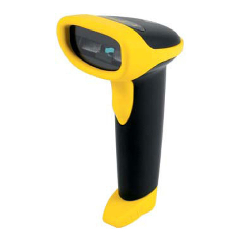
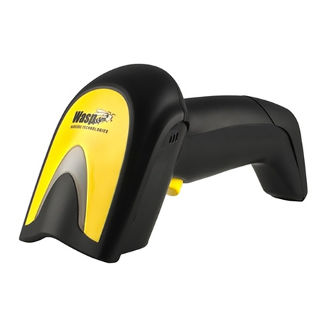
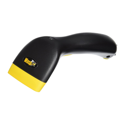
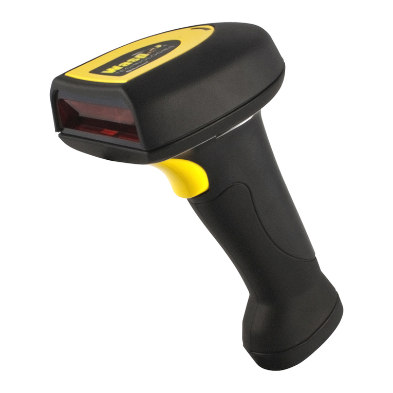
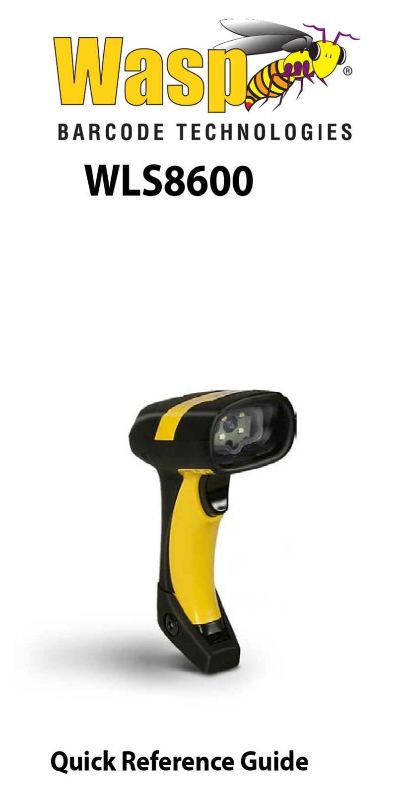
Wasp WLS8600 User manual

WLS8600
Reference Manual

Wasp Barcode Technologies
1400 10th Street
Plano, Texas USA 75074
©2000-2013 Wasp Barcode Technologies, Inc. (an unpublished work provided
under license).

CONTENTS
1INTRODUCTION .......................................................................................... 1
2INSTALLATION............................................................................................ 2
2.1 WLS8600 Interface Cable Connections ........................................................2
2.2 RS-232 Connection.......................................................................................4
2.3 USB...............................................................................................................4
2.4 IBM USB POS............................................................................................... 4
2.5 WEDGE Connection .....................................................................................5
2.6 PEN Emulation Connection...........................................................................5
3CONFIGURATION........................................................................................ 6
3.1 Configuration Methods..................................................................................6
3.1.1 Reading Configuration Barcodes .................................................................. 6
3.1.2 Copy Command ............................................................................................ 6
3.1.3 Sending Configuration Strings from Host...................................................... 6
3.2 Setup Procedures .........................................................................................7
3.3 WLS8600 Setup............................................................................................8
3.4 Interface Selection ........................................................................................9
3.5 USB Reader Configuration..........................................................................12
3.6 Changing Default Settings ..........................................................................14
RS-232 PARAMETERS .............................................................................. 15
USB PARAMETERS................................................................................... 20
WEDGE PARAMETERS............................................................................. 26
PEN EMULATION....................................................................................... 33
DATA FORMAT .......................................................................................... 38
POWER SAVE............................................................................................ 48
READING PARAMETERS .......................................................................... 50
DECODING PARAMETERS ....................................................................... 56
CODE SELECTION .................................................................................... 59
ADVANCED FORMATTING ....................................................................... 77
4REFERENCES ........................................................................................... 96
4.1 RS-232 Parameters ....................................................................................96
4.1.1 Handshaking............................................................................................... 96
4.1.2 ACK/NACK Protocol.................................................................................... 97
4.1.3 FIFO............................................................................................................ 97
4.1.4 RX Timeout................................................................................................. 98
4.2 Pen Parameters ..........................................................................................98
4.2.1 Minimum Output Pulse................................................................................ 98
4.2.2 Conversion to Code 39 and Code 128........................................................ 98
4.2.3 Overflow...................................................................................................... 98
4.2.4 Output and Idle Levels ................................................................................ 99
4.2.5 Inter-Block Delay......................................................................................... 99
4.3 Data Format................................................................................................ 99
i
WLS8600
4.3.1 Header/Terminator Selection .................................................................... 100
4.3.2 Define Special Key Sequence................................................................... 101
4.4 Power Save...............................................................................................109
4.4.1 Sleep State ............................................................................................... 109
4.4.2 Enter Sleep Timeout ................................................................................. 109
4.5 Reading Parameters .................................................................................110
4.5.1 Trigger Signal............................................................................................ 110
4.5.2 Trigger Click.............................................................................................. 110
4.5.3 Trigger-Off Timeout................................................................................... 110
4.5.4 Reads per Cycle ....................................................................................... 110
4.5.5 Safety Time............................................................................................... 111
4.6 Decoding Parameters ...............................................................................111
4.6.1 Ink-Spread ................................................................................................ 111
4.6.2 Overflow Control ....................................................................................... 111
4.6.3 Interdigit Control........................................................................................ 112
4.7 Advanced Formatting................................................................................ 112
4.7.1 Match Conditions ...................................................................................... 112
4.8 Configuration Editing Commands .............................................................113
4.9 Custom Default Configuration...................................................................114
4.10 Code Type Recognition.............................................................................114
4.11 Configuration Copying Commands ........................................................... 115
4.11.1 Copy WLS8600 Series.............................................................................. 115
4.12 Default Parameters for POS Terminals..................................................... 116
5TECHNICAL FEATURES ......................................................................... 117
5.1 WLS8600 .................................................................................................. 117
5.2 Status Indicators .......................................................................................118
5.3 Reading TABLEs ......................................................................................119
ii

NOTES
iii

WLS8600
GENERAL VIEW
WLS8600 READER
Figure A – WLS8600 Series Reader
Laser Output
Window
Cable Connector
LEDs
Trigger
iv

INTRODUCTION
1 INTRODUCTION
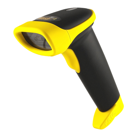
Wasp Barcode Technologies renews its range of industrial laser scanners introducing
the WLS8600 family. Robustness and ergonomics remain unsurpassed: clearly
audible beeper and bright "good read" LEDs for areas where noise levels are
normally high; the aim mode, which helps point to the right code, has now been
extended to the whole family. Optical parts are completely suspended on shock
absorbers and a careful choice of the body materials, such as the co-molded rubber,
protect the WLS8600 from damage due to "falls".
New enhanced architecture, based on an M16 high-speed microprocessor, enables
exceptional performance for promptness and reading speed of standard codes as
well as the ability to read poorly printed and damaged codes. Puzzle Solver
Technology™ adds further strength to the powerful engine of the WLS8600.
Your WLS8600 reader is supplied with its own Quick Reference Guide, which
provides connection, diagrams, reading diagrams, basic application parameter
settings, default values, and specific technical features. You can use either the Quick
Reference Guide or this Manual for initial configuration in order to set the default
values and select the interface for your application. This manual provides all the
necessary information for complete mechanical installation and system software
configuration.
1

WLS8600
2 INSTALLATION
Connections should always be made with power OFF!
CAUTION
2.1 WLS8600 INTERFACE CABLE CONNECTIONS
The WLS8600 reader incorporates a multi-standard interface, which can be connected
to a Host by plugging the correct interface cable into the connector and closing the
cable cover.
A. Rubber gasket
B. Plastic boot
C. Cable spacer
D. Cover
E. Strain relief
2

INSTALLATION
Follow the given procedure for correct cable insertion:
Slip the cover over the cable.
Push the plastic boot into the rubber gasket. Take care that the tab on the plastic
boot is aligned with the notch in the rubber gasket.
Push the plastic boot and gasket into the handle. Ensure that the “Front” marking
on the plastic boot is facing out, with the arrow pointing towards the front of the
scanner.
Insert the cable into the socket of the plastic boot.
Insert the cable spacer into the cable wire and slide it towards the handle.
Push the cover along the cable towards the reader, and hook it over the yellow
“tooth”.
Insert the strain relief into the cover and tighten the screw to fix the whole
assembly to the reader handle.
Connections should always be made with power OFF!
CAUTION
Align
1
2
3
4
5
6
7
Notch
Tab
Arrow
3

WLS8600
2.2 RS-232 CONNECTION
2.3 USB
2.4 IBM USB POS
4

INSTALLATION
2.5 WEDGE CONNECTION
2.6 PEN EMULATION CONNECTION
5

WLS8600
3 CONFIGURATION
3.1 CONFIGURATION METHODS
3.1.1 Reading Configuration Barcodes
This manual can be used for complete setup and configuration of your reader by
following the setup procedures in this chapter (see par. 3.2 for an overview).
If you wish to change the default settings, this manual provides complete
configuration of your reader in an easy way.
To configure your reader:
1) Open the folded page in Appendix C with the hex-numeric table and keep it
open during the device configuration.
2) Read the Enter Configuration code ONCE, available at the top of each page
of configuration.
3) Modify the desired parameters in one or more sections following the
procedures given for each group.
4) Read the Exit and Save Configuration code ONCE, available at the top of
each page of configuration.
Reference notes describing the operation of the more complex parameters are given
in chapter 0.
3.1.2 Copy Command
A previously configured device (Master), can be used to send its configuration directly
to other devices of the same type (Slaves). The particular procedure for each device is
given in par. 4.11.
3.1.3 Sending Configuration Strings from Host
An alternative configuration method is provided in Appendix A using the RS-232
interface. This method is particularly useful when many devices need to be
configured with the same settings. Batch files containing the desired parameter
settings can be prepared to configure devices quickly and easily.
6

CONFIGURATION
3.2 SETUP PROCEDURES
For WLS8600 Series readers, follow the setup procedures in pars. 3.3, and 3.4.
Proceed as shown in the following diagram:
BEGIN SETUP
Follow the procedure indicated
below.
1. Restore default parameters
Scan the Restore Default barcode at section 3.3,
WLS8600 Setup.
2. Scan the interface code
Go to section 3.4, Interface Selection and choose
the appropriate barcode for your application.
END SETUP
Your reader is now ready to read
barcodes using the default settings.
7

WLS8600
3.3 WLS8600 SETUP
1.
Read the restore default parameters code below.
Restore WLS8600 Default
Ì$+$*oÎ
After reading the above code, go to par. 3.4 Interface Selection.
8

CONFIGURATION
3.4 INTERFACE SELECTION
Read the interface selection code for your application.
RS-232
Standard
Ì$+CP0$-$Î
POS TERMINALS
Nixdorf Mode A
Ì$+CM2EC0$->Î
Fujitsu
ICL Mode
Ì$+CM1$-ÈÎ
Ì$+CM0$-ÃÎ
For POS terminal default settings refer to par. 4.12.
PEN
Ì$+CP6$-BÎ
9

WLS8600
WEDGE
IBM AT or PS/2 PCs
Ì$+CP500$-aÎ
IBM XT
PC Notebook
Ì$+CP503$-vÎ
Ì$+CP505$-ÈÎ
IBM SURE1
IBM Terminal 3153
Ì$+CP506$-$Î
Ì$+CP504$-}Î
IBM Terminals 31xx, 32xx, 34xx, 37xx:
To select the interface for these IBM Terminals, read the correct KEY TRANSMISSION code.
Select the KEYBOARD TYPE if necessary (default = advanced keyboard).
KEY TRANSMISSION MODE
make-only keyboard
Ì$+CP502$-oÎ
make-break keyboard
Ì$+CP501$-hÎ
KEYBOARD TYPE
advanced keyboard
Ì$+FK1$-ÉÎ
typewriter keyboard
Ì$+FK0$-ÄÎ
10

CONFIGURATION
WEDGE (CONTINUED)
ALT MODE
The ALT-mode selection allows barcodes sent to the PC to be interpreted correctly
independently from the Keyboard Nationality used. You do not need to make a
Keyboard Nationality selection.
(default = Num Lock Unchanged). Make sure the Num Lock key on your
keyboard is ON.
IBM AT - ALT mode
Ì$+CP507$-+Î
PC Notebook - ALT mode
Ì$+CP508$-2Î
WYSE TERMINALS
ANSI Keyboard
Ì$+CP509$-9Î
PC Keyboard
ASCII Keyboard
Ì$+CP510$-gÎ
Ì$+CP511$-nÎ
VT220 style Keyboard
Ì$+CP514$-ÇÎ
DIGITAL TERMINALS
VT2xx/VT3xx/VT4xx
Ì$+CP512$-uÎ
11

WLS8600
3.5 USB READER CONFIGURATION
The USB interface is compatible with the following Operating Systems:
Windows 98 (and later)
IBM POS for Windows
Mac OS 8.0 (and later)
4690 Operating System
USB Start-up
As with all USB devices, upon connection, the Host performs several checks by
communicating with the device. During this phase normal operations are suspended
(the LED on the WLS8600 reader blinks). Two basic conditions must be met before
the device is ready, the correct USB driver must be loaded and sufficient power must
be supplied to the reader.
For all systems, the correct USB driver for the
default USB-KBD interface is included in the Host
Operating System and will either be loaded
automatically or will be suggested by the O.S.
and should therefore be selected from the dialog
box (the first time only).
Normally the Host supplies sufficient power to
the device and the start-up phase ends
correctly. (The reader's LED stops blinking and
the reader emits the beep OK signal).
In rare cases, if the Host does not supply
sufficient power to the device, a dialog box will
appear on the Host and the device will be
blocked (the reader's LED continues blinking). In
this case, disconnect the USB device cable at the
Host (the reader's LED stops blinking), and then
try a different USB port as indicated by the
Operating System message. (The device emits
the beep OK signal. You can now read codes).
At this point you can read the USB interface configuration code according to your
application. Load drivers from the O.S. (if requested). When configuring the
USB-COM interface, the relevant files and drivers must be installed from the USB
Device Installation software. Contact WASP Technical Support for more information.
The device is ready. Successive start-ups will automatically recognize the previously
loaded drivers.
Connect device to
Host
Select desired USB
interface code
(USB-KBD is default)
Read test codes.
Device is READY
Load drivers
(if requested)
Load drivers
(if requested)
reader LED blinks
reader LED off -BEEP OK
First Start-Up
1
2
12

CONFIGURATION
USB
USB-KBD
Ì$+UA03$-:Î
USB-KBD-ALT-MODE
Ì$+UA04$-@Î
USB-KBD-APPLE
Ì$+UA05$-FÎ
USB-COM*
Ì$+UA02$-4Î
USB-IBM-Table Top
Ì$+UA00$-(Î
USB-IBM-Hand Held
Ì$+UA01$-.Î
* When configuring USB-COM, the relevant files and drivers must be installed from
the USB Device Installation software. Contact WASP Technical Support for more
information.
13

WLS8600
3.6 CHANGING DEFAULT SETTINGS
Once your reader is setup, you can change the default parameters to meet your
application needs. Refer to the preceding paragraphs for initial configuration in order
to set the default values and select the interface for your application.
In this manual, the configuration parameters are divided into logical groups making it
easy to find the desired function based on its reference group.
RS-232
USB
WEDGE
PEN EMULATION
DATA FORMAT parameters regard the messages sent to the Host system for all
interfaces except Pen Emulation.
POWER SAVE manages overall current consumption in the reading device.
READING PARAMETERS control various operating modes and indicator status
functioning.
DECODING PARAMETERS maintain correct barcode decoding in certain special
reading conditions.
CODE SELECTION parameters allow configuration of a personalized mix of codes,
code families and their options.
ADVANCED FORMATTING PARAMETERS allow code concatenation and
advanced formatting of messages towards the Host. It cannot be used with Pen
Emulation connections.
14
Other manuals for WLS8600
1
Table of contents
Other Wasp Barcode Reader manuals

Wasp
Wasp WLS8600 User manual

Wasp
Wasp WWS800 User manual

Wasp
Wasp WPL205 User manual

Wasp
Wasp WWS110i User manual

Wasp
Wasp WWS110i User manual

Wasp
Wasp WWS150i User manual

Wasp
Wasp WWS650 User manual

Wasp
Wasp WWS800 User manual

Wasp
Wasp N1181 Operating instructions

Wasp
Wasp CCD Scanner Operating instructions