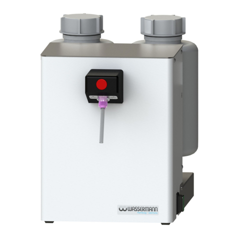
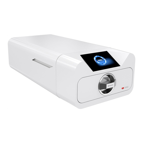
Wassermann Steam Box User manual

Steam Box
Cleaning cabin
for workpieces
USER MANUAL

Dear customer,
Thank you for choosing a product fro the Wasser ann range. Wasser ann Dental-
Maschinen incorporates the highest standards of quality and the latest technology.
In order to enjoy axi u perfor ance and years of trouble-free operation, please read
this user anual carefully before you connect this device and start work, and operate the
device according to the reco ended guidelines. The operation safety and the
functionality of this device can only be guaranteed if you follow both the general safety
guidelines and the applying laws to prevent accidents as well as the precautions given in
this user anual. We are not liable for any da ages which occur due to inappropriate
usage or faulty operation of this device.
Make sure that anyone using this device has read and understood this user
anual.
Keep this user anual in a safe place where it can be referred to as required at
any ti e.
The unit co plies with the relevant EU guidelines.
The unit is subject to the EU guidelines 2012/19/EU (WEEE Directive).
Company address:
Wasser ann Dental-Maschinen G bH
Rudorffweg 15-17
21031 Ha burg, Ger any
Phone : +49 (0)40 730 926 -20/ -24
export@wasser ann-dental.co
www.wasser ann.ha burg
www.facebook.co /Wasser annDental aschinen
Erstellt: 18.05.22 / KR, sc Version: 1 Abda pfbox 174970
.

Contents
1 Features............................................................................................................................4
2 Safety Sy bols used in this Manual.................................................................................4
3 Safety Guidelines..............................................................................................................5
4 Responsibility for Operation or Da age...........................................................................5
5 Application.........................................................................................................................6
6 Before Starting..................................................................................................................6
6.1 Transport....................................................................................................................6
6.2 Installation..................................................................................................................6
6.3 Storage.......................................................................................................................7
7 Installation/ Start-up..........................................................................................................7
7.1 Start-up.......................................................................................................................8
8 Operation..........................................................................................................................9
8.1 General Operating Instructions..................................................................................9
8.2 Handling of the Unit..................................................................................................10
9 Troubleshooting..............................................................................................................11
10 Care and Maintenance..................................................................................................12
10.1 Cleaning.................................................................................................................12
10.2 Maintenance...........................................................................................................13
10.3 Repairs...................................................................................................................15
10.4 Spare Parts.............................................................................................................15
10.5 Service Hotline 0049 (0)40 730 926 -20/ -24.........................................................15
10.6 Scope of Delivery/ Accessories/ Spare Parts........................................................15
10.7 Warranty.................................................................................................................16
11 Technical Data..............................................................................................................16
12 Disposing of the Unit.....................................................................................................17
12.1 Infor ation on Disposal for Countries within the EU.............................................17
13 EU Declaration of Confor ity.......................................................................................18
1 Features
•Co pact cleaning cabin for stea cleaning of workpieces
•Generous working opening (W= 285 , H= 235 )
•Quick stea extraction through powerful fan with run-on control
•Fan control selectable between continuous operation and auto atic ode
•Auto atic fan operation selectable via foot pedal or hand sensor control
•Extracted stea condenses using a floor filter, with the chassis floor serving as a
collecting tray
•This condensate drain tray can be e ptied using the ball valve on the side
•With practical grip plates: The work cabin can be quickly dis antled to clean the
condensate drain tray
•Separate protective filter in front of the fan
•Pleasant workspace illu ination with LED light
•Al ost entirely ade of stainless steel
•Low- aintenance, easy to clean and care
2 Safety Symbols used in this Manual
Warnin !
This is a warning of risk situations and dangers.
Failure to observe this warning could be life-threatening.
These warnings has to be observed.
Information!
This sy bol draws your attention to specific features that has to be observed.
4

3 Safety Guidelines
Configuring and operating this equip ent requires precise knowledge and observance
of the instructions in this user manual. The equip ent is designed only for its intended
application.
WARNING:
Servicing and repairs should be carried out only by authorised specialists.
Disconnect the power plug before starting any aintenance work.
Make sure that the equip ent is connected to the correct power source.
In auto atic ode, the fan has a run-on control, i.e. when the fan is switched off
using the foot pedal or hand sensor control, it continues to run for a few seconds.
Depending on the intensity of work, the water should be drained fro the collecting
tray via the ball valve, because the capacity is li ited.
4 Responsibility for Operation or Dama e
The responsibility for operating the device lies exclusively with the owner or user if said
device is incorrectly serviced, aintained or altered by persons not e ployed by an
authorised dealer or if the device is used in a anner contrary to its specified purpose.
The unit has to be aintained and operated in accordance with this user anual.
Wasser ann Dental-Maschinen G bH is not responsible for da age arising fro the
nonobservance of these instructions.
Warranty and responsibility provisions contained in the sales and supply conditions of
Wasser ann Dental-Maschinen G bH are not extended by these instructions.
5

5 Application
The Steam Box is a co pact work cabin for cleaning workpieces with stea . It is
designed for the cleaning of s all parts up to hand-sized parts.
A powerful fan, which quickly extracts the stea via a floor filter, and work area
illu ination with LED light ensure opti u visibility when working.
Only use the device for this type of application.
6 Before Startin
6.1 Transport
Before transporting the unit, ensure that it has been unplugged fro the power socket.
Make sure that it is packed correctly in order to avoid accidental da age.
Be sure to check for any transport da age when unpacking the goods. Note down
any da age if found.
6.2 Installation
Open the box, re ove the packing aterials, and carefully lift out the device and
accessories. Check the included accessories.
The unit has to stand horizontally on a steady and even surface.
Install the device in a place where it will not block the working area and the
functionality (take the di ensions into account).
Do not install the unit outdoors or in places without proper ventilation.
Before start-up, be sure the device reaches roo te perature.
6

6.3 Stora e
The unit location is very i portant when it co es to workplace safety, even if it is only to
be set up there for a short period. The roo should be dry, well ventilated and vibration-
free. An even te perature and wooden supports also help. The unit should not be stored
or set up outdoors. If the unit is to be stored for an extended period, protect it fro
oisture and dust.
7 Installation/ Start-up
Before starting the unit, connect up the following:
Install the drain hose included in delivery and provide a suitable drainage facility.
Note: For easier asse bly of the hose, the hose connector should be coated
thinly with soft soap or washing-up liquid.
ball valve (horizontal = open) drain hose
ball valve (vertical = closed)
7

7.1 Start-up
Before first usage of the cleaning cabin, please co pletely re ove all accessories
and the packaging aterial.
Before using the cleaning cabin, select the fan operating ode, i.e. whether the fan is
always switched on (continuous operation) or only when working (auto atic ode). In the
auto atic version you can choose between hand sensor and foot pedal control. If you
choose the foot pedal version, place the foot pedal in a position that is co fortable for you.
Finally, insert the power plug into the socket, aking sure that the ains and the unit
operate on the sa e voltage.
When walking past the unit, the auto atic anual sensor control ay cause the
fan to function unintentionally.
This is technically due to the set sensor detection range.
If the fan starts up too often unintentionally due to the space available, this can
be switched off by switching the fan to foot pedal operation or, in the case of a
longer break fro work, by turning off the green ain switch.
8

8 Operation
8.1 General Operatin Instructions
All instructions for using the unit, whether in verbal or written for , are based on our own
experience and experi entation and can only be regarded as guidelines.
Use heat-resistant gloves or holding tools for the parts to be cleaned.
If the unit is not used for a longer period of ti e, the ains plug should be pulled
out.
The filter inserts should be changed at suitable intervals in order to achieve
opti al suction perfor ance.
Since the capacity of the collecting tray is li ited, depending on the intensity of
work, you should let the collected water run off via the ball valve (drain).
9

8.2 Handlin of the Unit
•Select the appropriate operating ode of the fan using the selector switch.
•Turn on the green ain switch.
•Hold the workpiece to be cleaned in the work cabin and clean it with a stea gun.
ain switch selector switch „fan“
(continuous operation or auto atic ode)
selector switch „auto atic ode, control“
(hand sensor control or foot pedal control)
10

9 Troubleshootin
Fault Cause Solution
Fan does not switch off Continuous operation
selected
Control fan selector button
Auto atic ode - lag circuit
board defective
Please contact our service /
Repair (service workshop)
Auto atic ode - foot
switch defective
Switch to hand sensor or
Please contact our service
Auto atic ode - hand
sensor defective
Switch to footswitch or
Please contact our service
Fan does not turn on Fan defective Please contact our service /
Repair (service workshop)
Auto atic ode - foot
switch defective
Switch to hand sensor or
Please contact our service
Auto atic ode - hand
sensor defective
Switch to footswitch or
Please contact our service
Dark workroo LED lighting defective Please contact our service
Stea box without
function
Main switch (green)
defective
or
fuse of the socket defective
Please contact our service
or
Check fuse / replace if necessary - if
defective repeatedly, then please
contact service - if necessary,
service workshop
If the above reco endations do not solve the proble , contact your dental depot
or our service depart ent.
11

10 Care and Maintenance
10.1 Cleanin
Disconnect the power plug before starting any aintenance work.
The identification plate has always to be kept in easily legible condition and has
not to be re oved.
Re ove external dirt fro ti e to ti e with so e for of cold cleaner.
Use only cold cleaners to avoid da aging the paintwork or re oving the lettering.
Depending on the intensity of work and the degree of soiling, the viewing
window in the ceiling area (above) of the work area should be cleaned for
opti al illu ination of the work area.
Viewing window
Sensors
The two sensors ounted outside on the front of the housing should be cleaned
at regular intervals to ensure trouble-free operation.
12

10.2 Maintenance
Check the filter inserts for leakage at regular intervals. If the dirt is too heavy, the
corresponding filter ele ents ust be replaced in order to ensure opti al stea
extraction.
Filter ele ents (4 pieces) - floor filter (work space)
To check the filter ele ent - protective filter (fan), you ust re ove the front of the
housing with the stea cabin, as described below. Then unscrew the knurled screws (2x)
on the rear and re ove the filter holder. After checking or replacing the filter ele ent,
reasse ble the filter holder.
13

Check the collecting tray for deposits or blockages in the drain hole at regular intervals.
For opti al drainage of the collecting tray, the opening should be kept free and cleaned.
To do this, re ove the two screws in the front of the housing and carefully pull the front of
the housing forward with the help of the two grip plates. After that disconnect the plug
connection (6-pin) and then pull the front of the housing with the stea cabin forward
using the grip plates and set it aside. Now you can check the collecting tray (= chassis
floor) and the drain hole as well as other filter ele ents. Then reasse ble the stea box
accordingly.
Screws (2x) Case front Filter ele ent - protective filter (fan)
Stea cabin Filter holder Knurled nut (2x)
Filter ele ent - protective at (workspace) Plug connection (6-pin)
Grip plate Chassis floor = collecting tray
14

10.3 Repairs
Servicing or repairs to the unit has only to be carried out by qualified technicians.
Only original spare parts are to be used. Responsibility for the product is voided
if unauthorised persons alter it or if inappropriate co ponents are installed.
10.4 Spare Parts
If necessary please contact our service hotline phone.
10.5 Service Hotline 0049 (0)40 730 926 -20/ -24
10.6 Scope of Delivery/ Accessories/ Spare Parts
Steam Box (Item no. 174970)
Included in delivery:
•Drain hose, 2
Accessories Item no.
Floor filter (work space), 1 piece 174508
Protective at (workspace), 1 piece 174507
Protective filter (fan), 1 piece 174509
Drain hose, per eter 320018
15

10.7 Warranty
The warranty period for our equip ent is 12 onths. If faults occur within the
warranty period, contact your dental depot or get in touch directly with our service
depart ent.
Your equip ent should only be operated in perfect condition. If faults occur which
could har operators or third parties, the unit should not be used until it has been
fixed.
This warranty does not cover da age caused by i proper use, external echanical
causes, transport da age or interference with the unit by unauthorized persons.
11 Technical Data
Steam Box Item no.: 174970
Voltage* 220–240 V / 50/60 Hz
Power consu ption 0.8 A
Output 140 W
W x H x D ( ax.) 421 x 476 x 549
W x H x D (housing) 393 x 476 x 515
W x H (working opening) 285 x 235
Protection class IP 44
Weight 26.5 kg
Other voltages on request.
The noise level of the unit a ounts to ≤ 70 dB (A).
Technical changes reserved.
16

12 Disposin of the Unit
The unit has to be disposed by an authorized recycling operation. The selected co pany
has to be infor ed of all possibly health-hazardous residues in the unit.
12.1 Information on Disposal for Countries within the EU
To conserve and protect the environ ent, prevent environ ental pollution and
i prove the recycling of raw aterials, the European Co ission adopted a
directive that requires the anufacturer to accept the return of electrical
and electronic units for proper disposal or recycling.
Within the European Union units with this sy bol should not therefore be disposed of
in unsorted do estic waste.
For ore infor ation regarding proper disposal please apply at your local authoritie.
Your Contact at Wasser ann Dental-Maschinen
You have questions concerning our products or services?
Contact us! We guarantee quickest possible handling and
we will provide you personally with co petent, dedicated
help. Thank you for contacting us!
Phone: +49 (0)40/ 730 926 - 24
export@wasser ann-dental.co
17

13 EU Declaration of Conformity
in accordance with 2014/35/EU (Low Voltage Directive) and 2014/30/EU (Electro agnetic
Co patibility Directive) and 2006/42/EC (Machinery Directive) and 2011/65/EU (RoHS
Directive)
Manufacturer: W A S S E R M A N N
Dental-Maschinen G bH
Rudorffweg 15-17
21031 Ha burg
Ger any
Product description: xxx for dental
applications
Model: Stea Box Ite no. 174970
Applicable
standards:
DIN EN 61010-1
DIN EN 61000-6-3
DIN EN 61000-6-1
DIN 45635-1
DIN EN 60335-1
Hier it wird bestätigt, dass die oben bezeichnete Maschine den genannten EU-Richtlinien
entspricht. Diese Erklärung wird ungültig, falls die Maschine ohne unsere Zusti ung
verändert wird.
This is to confir that the above entioned achine co plies with the described EU
guidelines. This declaration beco es invalid if the achine is odified without our
approval.
Cette achine est confor e aux nor es en vigueur d´Union européenne. Cet avis est
nul et non avenant si cette achine est odifiée sans notre accord.
Esta áquina, anterior ente encionada, cu ple con los li ites requeridos por el
regla ento UE. Ahora bien, esta declaración quedará invalidada en caso de realizar
odificaciones al aparato sin nuestra aprobación.
Hier ee wordt bevestigd dat bovengenoe de achine voldoet aan de voorgeschreven
EU nor en. Deze verklaring verliest geldigheid als er zonder onze uitdrukkelijke
toeste ing wijzigen aan de achine worden aangebracht.
Place, date: Ha burg, 2022-05-18 Co pany sta p :
Signature: ________________________
Sven Wasser ann
(Managing Director)
18

Notes:
19

This manual suits for next models
1
Table of contents
Other Wassermann Dental Equipment manuals

Wassermann
Wassermann HSS-AZ User manual

Wassermann
Wassermann Sidomix II User manual

Wassermann
Wassermann HSS-88 Operating and safety instructions

Wassermann
Wassermann Timobil User manual

Wassermann
Wassermann WAPO-Ex User manual

Wassermann
Wassermann HSS-88 Operating and safety instructions

Wassermann
Wassermann SG-1/2 D User manual

Wassermann
Wassermann HSS-99 Operating and safety instructions

Wassermann
Wassermann HSS-88 User manual

Wassermann
Wassermann Wapo-Mat III User manual