Wassermann Gobi Classic User manual

Fine Blasting Unit
Gobi Classic
USER MANUAL

Dear customer,
Thank you for choosing a product from the assermann range. assermann Dental-
Maschinen incorporates the highest standards of quality and the latest technology.
In order to enjoy maximum performance and years of trouble-free operation, please read
this user manual carefully before you connect this device and start work, and operate the
device according to the recommended guidelines. The operation safety and the
functionality of this device can only be guaranteed if you follow both the general safety
guidelines and the applying laws to prevent accidents as well as the precautions given in
this user manual. e are not liable for any damages which occur due to inappropriate
usage or faulty operation of this device.
Make sure that anyone using this device has read and understood this user
manual.
Keep this user manual in a safe place where it can be referred to as required at
any time.
The unit complies with the relevant EU guidelines.
The unit is subject to the EU guidelines 2012/19/EU ( EEE Directive).
Company address:
assermann Dental-Maschinen GmbH
Rudorffweg 15-17
21031 Hamburg, Germany
Phone : +49 (0)40 730 926 -20/ -24 Fax.: +49 (0)40 730 37 24
www.wassermann.hamburg
www.facebook.com/ assermannDentalmaschinen
Erstellt: 14.11.18/ msc Version: 1 Auftrag: 190881/ 001
.

Contents
1 Features....................................................................................................................................... 4
2 Safety Symbols used in this Manual.............................................................................................6
3 Safety Guidelines.........................................................................................................................6
4 Responsibility for Operation or Damage.......................................................................................7
4.1 arranty..........................................................................................................................................7
5 Application....................................................................................................................................7
6 Before Starting............................................................................................................................. 8
6.1 Transport.........................................................................................................................................8
6.2 Installation.......................................................................................................................................8
6.3 Storage............................................................................................................................................8
7 Installation/ Start-up.....................................................................................................................9
8 Operation................................................................................................................................... 10
8.1 General Operating Instructions.....................................................................................................10
8.2 Sand-blasting, Roughening, Polishing..........................................................................................10
9 Troubleshooting.......................................................................................................................... 11
10 Care and Maintenance.............................................................................................................12
10.1 Cleaning......................................................................................................................................12
10.2 Maintenance/ Replacing worn Components...............................................................................13
10.2.1 Sleeve Replacement............................................................................................................13
10.2.2 Screen Replacement...........................................................................................................13
10.2.3 LED Replacement................................................................................................................14
10.2.4 Conducting Hose Replacement...........................................................................................15
10.2.5 Nozzle Replacemant............................................................................................................16
10.2.6 Overview of Nozzles and Blasting Material.........................................................................16
10.2.7 Protection Filter Replacement..............................................................................................17
10.2.8 ater Separator...................................................................................................................17
10.3 Scope of Delivery/ Accessories/ Spare Parts..............................................................................18
10.3.1 Spare Parts..........................................................................................................................19
10.3.2 Service Hotline 0049 (0)40 730 926 -20/ -24.......................................................................19
10.4 Repairs........................................................................................................................................19
11 Technical Data..........................................................................................................................19
12 Disposing of the Unit................................................................................................................20
12.1 Information on Disposal for Countries within the EU..................................................................20
13 EU Declaration of Conformity...................................................................................................21
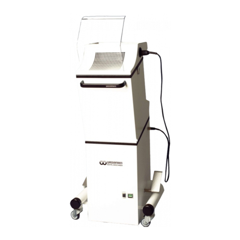
1 Features
This precision fine blasting unit of the assermann-brand offers you the highest quality
and most advanced technology.
This 2-chamber-unit is perfect for sand-blasting, roughening and polishing. The unit works
precisely and requires little maintenance. The entire system is continiously under pressure
and is therefore always ready for use. The relation between air and the blasting material is
set at the factory. It is determined by the size of the drillings. Adjustment of the abrasive
pressure is done by using the pressure reducer at the rear. This set discharge velocity
determines the outflowing amount of blasting media (while the relation is kept optimal and
constant).
This unit is equipped with a plug socket (power consumtion: max. 8 A).
4

•Stable fine blasting unit with 2 chambers
•Precise working pressure of 0.8–6 bar with pressure gauge control
•Genuine quick start/stop function, cost savings thanks to noticeable low
consumption of blasting material
•Permanent pressure system: Prevents contamination and moisture of blasting
material
•Comfortably to handle with ergonomically shaped handpieces
•Easy foot-controlled operation
•Rapid ventilation of the high quality blasting material containers made of metal for
rapid re-filling and changing of blasting material
•Special particularly durable hoses
•High hygiene standard because of changeable sleeves
•Convenient colour coding system
•Easy choise of the desired blasting material by using the selection switch for colour
circuit settings
•Specially coated safety screen for ideal visibility
•Optimum workspace illumination, protected LED lamp
•Blasting material tanks made of metal, high quality construction
•Designed for long durability
•Simple cleaning due to stay-clean surfaces: High quality stainless steel and robust
plastic powder coating
•Air inlet membrane: If needed cut in the rubber vertically and horizontally to achieve
an optimum exhaust air stream into the vent of the connected suction unit
•ith plug socket (power consumption max. 8 A), e.g. for a suction unit
•Connection option for a suction unit: Extractor nozzle Ø 75 mm exterior
•Available as accessories: Extractor nozzle Ø 40 mm exterior (Item no. 143385)
Extractor nozzle Ø 50 mm exterior (Item no. 190286)
5

2 Safety Symbols used in this Manual
Warning
This is a warning of risk situations and dangers.
Failure to observe this warning could be life-threatening.
These warnings has to be observed.
Information
This symbol draws your attention to specific features that has to be observed.
3 Safety Guidelines
Configuring and operating this equipment requires precise knowledge and observance
of the instructions in this user manual. The equipment is designed only for its intended
application.
WARNING:
Servicing and repairs should be carried out only by authorised specialists.
Disconnect the power plug before starting any maintenance work.
Make sure that the equipment is connected to the correct power source.
Because of a safety switch working is only possible while the blasting
chamber is closed. Otherwise the safety switch cuts power to the system.
Please wear safety goggles
WARNING:
Never connect to an oxygen bottle. Risk of dust explosion.
6

4 Responsibility for Operation or Damage
The responsibility for operating the device lies exclusively with the owner or user if said
device is incorrectly serviced, maintained or altered by persons not employed by an
authorised dealer or if the device is used in a manner contrary to its specified purpose.
The unit has to be maintained and operated in accordance with this user manual.
assermann Dental-Maschinen GmbH is not responsible for damage arising from the
nonobservance of these instructions.
arranty and responsibility provisions contained in the sales and supply conditions of
assermann Dental-Maschinen GmbH are not extended by these instructions.
4.1 Warranty
The warranty period for our equipment is 12 months. If faults occur within the
warranty period, contact your dental depot or get in touch directly with our service
department.
Your equipment should only be operated in perfect condition. If faults occur which
could harm operators or third parties, the unit should not be used until it has been
fixed.
This warranty does not cover damage caused by improper use, external mechanical
causes, transport damage or interference with the unit by unauthorized persons.
5 Application
This 2-chamber blasting unit is designed for blasting, roughing and polishing, and to bring
a lasting finish to the workpiece.
Only use the device for this type of application.
7

6 Before Starting
6.1 Transport
Before transporting the unit, ensure that it has been unplugged from the power socket.
Make sure that it is packed correctly in order to avoid accidental damage.
Be sure to check for any transport damage when unpacking the goods. Note down
any damage if found.
6.2 Installation
•Open the box, remove the packing materials, and carefully lift out the device and
accessories.
•Avoid lifting the unit on the mounting bracket of the air control unit because it could
bend or break.
•The unit has to stand horizontally on a steady and even surface.
•Check the included accessories.
Install the device in a place where it will not block the working area and the
functionality (take the dimensions into account).
Do not install the unit outdoors or in places without proper ventilation.
Before start-up, be sure the device reaches room temperature.
6.3 Storage
The unit location is very important when it comes to workplace safety, even if it is only to
be set up there for a short period. The room should be dry, well ventilated and vibration-
free. An even temperature and wooden supports also help. The unit should not be stored
or set up outdoors. If the unit is to be stored for an extended period, protect it from
moisture and dust.
8

7 Installation/ Start-up
Before starting the unit, connect up the following:
•Connect the unit to the compressed-air line.
•The fine blasting unit also has to be connected to an external suction unit.
•The nozzle for a suction unit is at the lower rear.
•Finally, insert the power plug into the socket, making sure that the mains and
the unit operate on the same voltage (100-240 V / 50/60 Hz).
Power consumption of the interated plug socket: max. 8 A
Before using the unit, let it stand with open chambers until it has reached
room temperature.
It is absolutely necessary to switch the unit off before filling.
•The red chamber should be filled with 110-250 my material as standard.
•The blue chamber should be filled with 50-110 my material as standard.
Please pay attention to the maximum filling capacaty of the chambers which is
marked inside the chamber. The chambers are only allowed to be filled up to 2.5 cm
from the upper chamber edge.
All chambers are vented by pressing the according air vent knob.
The chambers can be screwed on when they are completely pressureless. The
chambers are vented by pressing the tank cover air vent knob. Switch off the unit
and press these knobs of the screwed-on cover until no outflowing air can be heard.
Before setting on the containers you have to assure that the threads and
sealing surfaces are free of blasting media grains.
•Screw on the screwed-on cover (hand-screwed). hen all chambers have been
screwed on the unit is ready for use and can be switched on.
•Insert the power plug firmly into the power outlet (100-240 V / 50/60 Hz).
•Switch on the main switch (green toggle switch).
•Set the pressure reducer to working pressure. There must be no hissing noise.
Otherwise, please retighten the screwed-on cover by hand.
9

8 Operation
8.1 General Operating Instructions
All instructions for using the unit, whether in verbal or written form, are based on our own
experience and experimentation and can only be regarded as guidelines.
8.2 Sand-blasting, Roughening, Polishing
•Switch on main switch (green toggle switch).
•Set the working pressure to the desired value.
•The pressure is adjusted by pulling the knob and turning to the
left (pressure decreases) or to the right (pressure increases).
•Then lock the knob by pressing it down.
•The set pressure can be read via the manometer. By varying the pressure, the
outflow velocity is varied and thus also the amount of blasting material.
•Determine the blasting chamber with the selector switch installed in the working
space.
•Pick up the handpiece according to the selected color.
•Blasting process starts by using the foot switch.
Due to the operating condition, the amount of blasting media flow may
change when the blasting media amount decreases.
By slightly tilting the unit it is possible to continue working for a short time.
However, this is an indication that you have to refill blasting media.
10

9 Troubleshooting
Fault Cause Solution
irregular flow of
blasting material
too little blasting material in
container
re-fill the container
nozzle on stylus too small use larger nozzle
blasting material is moist use blasting material of correct dryness
no flow of blasting
material
container empty re-fill the container
main nozzle and/or steel
hose blocked
•use recommended, dry blasting
material
•unscrew nozzle on the stylus
trigger blasting process
blasting material should flow
•if necessary, build up
counterpressure by pressing the
hose
•clean the nozzle (make the stuck
grains come loose)
•if the obstruction persists, use
compressed air or a needle to
clean the nozzle
wrong blasting container please switch to the correct blasting
container
chamber nozzle blocked Contact our Service:
•item no. 190494
(Key for chamber nozzle)
is necessary for dismounting
•clean the nozzle (make the stuck
grains come loose)
•if the obstruction persists, use
compressed air or a needle to
clean the nozzle
too little pressurised air < 3
bar
increase pressure
decreasing and/or
to low blasting
pressure
protective filter (item no.
610039 Small Filter Plate
D14 X 1.5) blocked and/or
buckled closed
change filter plate
item no. 610039
Small Filter Plate D14 X 1.5
If the above recommendations do not solve the problem, contact your dental depot
or our service department.
Remarks: Obstructions normally occur from soiled or lumply blasting material. If the sand
draws moisture, check the condensator. Please also see page 17, 10.2.8 ater Separator.
11

10 Care and Maintenance
10.1 Cleaning
Disconnect the power plug before starting any maintenance work.
The identification plate has always to be kept in easily legible condition and has
not to be removed.
Remove external dirt from time to time with some form of cold cleaner.
Use only cold cleaners to avoid damaging the paintwork or removing the lettering.
The equipment should be cleaned at regular intervals to ensure trouble-free
operation.
It requires only normal cleaning (sponge, damp cloth, mild detergent) and no further
chemical additives.
•Never use strong and abrasive solvents for cleaning the screens.
•The inside of the chambers and the protection screens can be cleaned with
compressed air. Fine-dust will be sucked out by the dust-extractor.
•Coarse abrasive, which cannot be removed by the suction system, could be
removed through the disposal port.
12

10.2 Maintenance/ Replacing worn Components
Always disconnect the power plug before starting any maintenance work.
This unit does not require any special maintenance. Just make sure that the device is kept
clean.
However, after using the unit a certain time, it will be necessary to replace some parts.
Please take care of the following parts:
10.2.1 Sleeve Replacement
Sleeves can also be replaced with gloves. The procedure is the same.
•Loosen the connector with pliers and unscrew the throughgrip (4 screws).
•Pull off the old sleeve and put on the new one so that it completely covers the
opening.
•Attach the new connector. Take care that the closing of the connector is placed
inside the notch of the opening.
•Tighten the opening.
10.2.2 Screen Replacement
•Open the flap and loosen the five knurled nuts.
•Remove the guide rail
•Fold the screen to the front and pull it out. Please take care of the spacer reels.
•Replace the specially coated safety screen and reassemble everything in reverse
order.
13

10.2.3 LED Replacement
•For changing the LED lamp open the safety screen first.
•Than remove the lamp cover [A] by loosen the knurled screws [B].
•Resolve the plug connection of the LED power cable.
•Than remove the two screws [C] by using an Allen wrench.
•Remove the defective LED strip [D] from the retaining angle [E] and change it.
•Reassemble everything in reverse order.
14
A
B
C
D
E
B
C

10.2.4 Conducting Hose Replacement
Before changing, the mains plug must be disconnected and the pressurised air connection
detached.
The pressure of all the tanks must be released (see page 9, Start-up).
•Take sieve unit out of the chamber.
•Lay the unit on its side so that you have access to the bottom of the unit.
•To detach the desired hose from the tank, solve the black hose clamp with a pliers,
remove the hose from the chamber nipple
•Pull and/or lever the silver handle on the squeezing valve, with the other hand
pulling the hose through the through-put and into the interior.
•Remove the slotted hose protection.
In principle the installation takes place exactly in the reverse manner:
•First, put the slotted protective hose over the blasting hose.
•Than insert the hose from the interior of the chamber through the hole in the rear.
•Than insert the hose through the squeezing valve.
•TIP: Slightly rotate the hose for easier passage of the fabric.
•TIP: Put the hose clamp already now around the hose.
•Than put the hose with the clamp on the nipple of the tank.
•The fabric must be completely pulled over the rubber. Should this be difficult to
achieve then push the fabric outwards from the stylus right to the end until enough
fabric is available.
•Put the hose clamp around the nipple of the tank and compress with the pliers.
•Put the unit back in an upright position and re-install the sieve grille. Please take
care that the blasting hoses run along under the sieve grille.
15

10.2.5 Nozzle Replacemant
The replacement is very easy. Simply unscrew the old nozzle and screw on a new one.
Important : Before setting up a new nozzle, shortly operate the unit and blow away
old blasting material which may remain inside the hose.
Take care that the nozzle always corresponds to the size of the used blasting
material (please see the following chart).
10.2.6 Overview of Nozzles and Blasting Material
Colour code* (tank/ handpiece): yellow blue green red
Fine blasting nozzle (handpiece) 0,6 0,8 0,8 1,2
Nozzle (tank) 1,4 ( < 110 µm) X X
Nozzle (tank) 2,0 ( > 110 µm) X X
Aluminium Oxyde 50 µm +++ ++ + -
Aluminium Oxyde 110 µm + +++ +++ +
Aluminium Oxyde 250 µm - - + +++
Glass Beads 50 µm ++ + - -
Glass Beads 110 µm + ++ +++ +
Glass Beads 125 µm - + ++ +++
Annotation:
X = Combination fine blasting nozzle (handpiece)/ nozzle (tank)
- = does not fit
+ = fits
++ = fits well
+++ = optimal
The ratings in the table are standard values that may vary depending on the nature of the blasting material.
*This colour code with the above mentioned combination of the nozzles is delivered as standard
(see page 18).
16

10.2.7 Protection Filter Replacement
After some time of usage the filter inlet may become clogged. This filter inlet is situated
directly behind the filter block onto the blasting material container.
•Unscrew and remove the rear panel.
•Unscrew the screws of the filter block with the help of a 3-Allen key.
•Change the filter inlet inside the filter block (just press lightly) and screw it back onto
the blasting material container.
10.2.8 Water Separator
The pressure reducer at the rear of the unit comes with an integrated water separator, that
absorbs any condensation coming out of the compressor. It must be checked regularly and
at the latest when the max. level is reached, it must be emptied. To do this, pull the beige
drain down so that the water can flow into the container you have placed under the unit.
17
Filter Block
Filter Inlet*
*(Item no. 610039 Small Filter Plate D14 X 1.5)

10.3 Scope of Delivery/ Accessories/ Spare Parts
Included in Delivery Item no.:
Gobi Classic incl. 2 nozzles: 0.8 (blue), 1.2 (red) 190881
Compressed air hose, PVC-hose D 8x6 cloth (blue), 2 m –-
Delivered as standard: Supply line 3 core with angle plug 592012
Delivered only on request: Supply line 3 core US 13 A 592011
Accessories/ Spare Parts Item no.:
Extractor nozzle Ø 40 mm exterior 143385
Extractor nozzle Ø 50 mm exterior 190286
Compressed air hose, PVC-hose D 8x6 cloth (blue), per meter 320026
Spare sleeve, per piece 190175
Spare hose -blue- 190738
Spare hose -red- 190729
Spare protection sheet with special coating 190432
18

We recommend the use of Wassermann blasting materials and our low-
pressure suction units SG-10, SG-1/1 and SG-1/2 D with a long-life brushless
motor and an extra large micro fine dust filterbag.
10.3.1 Spare Parts
If necessary please contact our service hotline phone.
10.3.2 Service Hotline 0049 (0)40 730 926 -20/ -24
10.4 Repairs
Servicing or repairs to the unit has only to be carried out by qualified technicians.
Only original spare parts are to be used. Responsibility for the product is voided
if unauthorised persons alter it or if inappropriate components are installed.
11 Technical Data
Gobi Classic Item no.: 190881
Voltage 100–240 V / 50/60 Hz
Power consumption 0.2 A
Plug socket power consumption max. 8 A
Output 50
x H x D 444 x 372 x 520 mm
eight 14 kg
Noise level ≤ 70 dB (A)
Tank capacity 420 cm³
Compressed air connection 3-6 bar
orking pressure 0.8-6 bar
Extractor nozzle 75 mm exterior
Technical changes reserved.
19

12 Disposing of the Unit
The unit has to be disposed by an authorized recycling operation. The selected company
has to be informed of all possibly health-hazardous residues in the unit.
12.1 Information on Disposal for Countries within the EU
To conserve and protect the environment, prevent environmental pollution and
improve the recycling of raw materials, the European Commission adopted a
directive that requires the manufacturer to accept the return of electrical
and electronic units for proper disposal or recycling.
ithin the European Union units with this symbol should not therefore be disposed of
in unsorted domestic waste.
For more information regarding proper disposal please apply at your local authoritie.
20
This manual suits for next models
1
Table of contents
Other Wassermann Dental Equipment manuals

Wassermann
Wassermann HSS-99 User manual

Wassermann
Wassermann Wapo-Ex 12 II User manual

Wassermann
Wassermann WW-33 User manual

Wassermann
Wassermann HSS-88 Operating and safety instructions

Wassermann
Wassermann SG-1/2 D User manual

Wassermann
Wassermann Wapo-Mat III User manual

Wassermann
Wassermann HSS-99 Operating and safety instructions

Wassermann
Wassermann WAPO-Ex User manual

Wassermann
Wassermann HSS-88 Operating and safety instructions

Wassermann
Wassermann Steam Box User manual