Tyco CCU/IO-485 Configuration guide

1of 9 REF: CCU/IO-485.DOC REV: C June 20, 2000
34 Corporate Drive
Southgate Corporate Park
CANNON HILL 4170
AUSTRALIA
Tel: +61 7 3318 6900
Fax: +61 7 3318 6905
CCU/IO-485 ( and CCU/I-485 ) Install Instructions
Part #: CCU/IO-485 ( or CCU/I-485 )
This equipment is designed for installation and service by fully qualified field engineers. No user
serviceable or installation parts inside.
Description:
CCU/IO-485 :
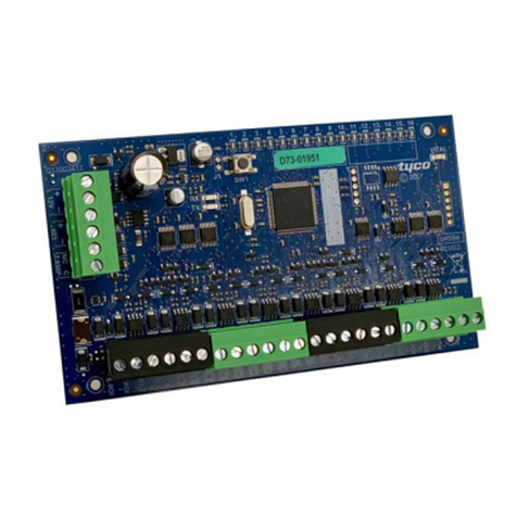
The CCU/IO-485 has 8 relay outputs and 8 supervised inputs.
CCU/I-485 :
The CCU/I-485 is exactly the same as the CCU/IO-485 except that the 8 outputs on the
CCU/IO-485 are replaced with 16 unsupervised inputs. Any CCU/IO-485 mentioned in this
document may be replaced with a CCU/I-485. This document will use CCU/IO-485s in all of
it’s examples.
Supplied:
1 x CCU/IO-485 board with firmware for RS485/RS232 interface
1 x Mounting Bracket
1 x Power connector for CCU/IO
1 x Supervision relay connector for CCU/IO
1 x RS485 interface connector
You will need:
1 x cable from 24V DC power source to CCU/IO. Connector supplied.
If connecting to CCU/485-IO
1 x RS485 interface cable ( see later for wiring information)
If connecting to CCU/422-IO, CCU/232-IO or CCU/FIBRE-IO
1 x RS232 interface cable (see later for wiring information)
Power Requirements:
Typical: 200mA at 24VDC
Voltage Input: 20-30 VDC

2of 9 REF: CCU/IO-485.DOC REV: C June 20, 2000
Board Layout:
CCU/IO-485:
CCU/I-485: ( Note the outputs are replaced with 2 inputs each. The middle pin on each is 0V. )

3of 9 REF: CCU/IO-485.DOC REV: C June 20, 2000
Installation of CCU/IO-485:
If connecting to CCU/422-IO, CCU/232-IO or CCU/FIBRE-IO -
•If connecting the CCU/IO-485 to a CCU/232-IO, CCU/422-IO or CCU/FIBRE-IO then place
jumpers on JP30 as shown below and connect the RS232 port ( CHN_A ) of the CCU/IO-485 to
port C of the CCU/232-IO, CCU/422-IO or CCU/FIBRE-IO using the following connection
diagram.
CCU/IO-485 RS232 9PIN
(DTE) CCU/232-IO, CCU/422-IO or
CCU/FIBRE-IO Channel C
9PIN (DCE)
2 3
3 2
5 5
JP30
•This configuration only allows one CCU/IO-485 to be connected to the network for each CCU/232-
IO, CCU/422-IO or CCU/FIBRE-IO.

4of 9 REF: CCU/IO-485.DOC REV: C June 20, 2000
If connecting to a CCU/485-IO -
•If connecting the CCU/IO-485 to a CCU/485-IO then place jumpers on JP30 as shown below and
connect the RS485 ( SKT33 ) port of the CCU/IO-485 to port A or B of the CCU/485-IO using
the following connection diagram. Up to eight CCU/IO-485 boards can be chained off one channel
of the CCU/485-IO, giving up to 16 CCU/IO-485 boards connected to one CCU/485-IO.
Appendix A contains informatin on wiring for this configuration.
CCU/IO-485 RS485 (SKT33) CCU/485-IO Channel A or B
+R+
-R-
middle pin middle pin
JP30
•This configuration only allows sixteen CCU/IO-485 boards to be connected to the network for each
CCU/485-IO.

5of 9 REF: CCU/IO-485.DOC REV: C June 20, 2000
For all installations -
•For normal operation a jumper should be in place across A on JP20.
•If hardware supervision is required connect the relay output from the CCU/IO-485 to a suitable
input on the FIP (software supervision does not require this). The relay socket is located next to the
power connector. The relays will energise when Supervision failure is detected.
•Connect the 24V DC power source to the supplied connector. The power connector is next to the
CHN_C port. Pin connections are:
PWR (+24VDC) RETURN/COM(0V) BATTERY(24V)
These connections are written on the board. If the 24V power source is Uninterruptible, then
there is no need to connect the BATtery connection.
Pin number Function
1 24V
2 COM
3 BAT
Connecting the inputs and outputs to the CCU/IO-485:
•The outputs on the CCU/IO-485 are relays that have a common ( COM ), normally open ( NO ) and
normally closed ( NC ) output, as shown in the Board Layout ( page 1 ). When the relay is not
energised the common line in shorted to the normally closed line. When the relay is energised the
common line is shorted to the normally open output.
•The inputs on the CCU/IO-485 run off a 20mA loop. To obtain supervision on these inputs a 220
ohm terminating resistor must be added across the remote end. For inputs that are a distance from the
CCU/IO the line should be powered by a higher voltage to allow for line loss ( note that the value of
the supervision resistor also changes ). Refer to Appendix A for details.
Operation of LEDs:
•CHN_A has a Green and a Yellow LED. The green LED glows when the port is operating correctly.
The yellow LED glows when the port is not operating correctly, or there has been supervision failure
on this port.
For the CCU/IO-485:
•Each output relay has two leds associated with it. When the relay is energised and switches the green
LED glows. If the relay fails to switch when it is energised the yellow LED glows.
For the CCU/I-485:
•The LEDs used for the output relay on the CCU/IO-485 are unused on the CCU/I-485.
6of 9 REF: CCU/IO-485.DOC REV: C June 20, 2000
Configuration of CCU/IO:
•You must use the jumpers JP31 (1 to 8) on the CCU/IO to configure the local CCU Node address.
Each CCU Node is numbered sequentially from Address 1. Boards connected to Channel A on the
CCU/485-IO must have addresses from 1 to 8 inclusive. Boards connected to Channel B on the
CCU/485-IO must have addresses from 9 to 16 inclusive. For example if 12 CCU/IO-485s are
connected to a CCU485/IO ( 8 connected on Channel A and 4 on Channel B ), then the 8 CCU/IO-
485s on Channel A will be given the Addresses 1 to 8. The 4 CCU/IO-485s on Channel B will be
given the Addresses 9 to 12. Address 0 CANNOT BE USED. If a CCU/IO-485 is connected to a
CCU/232-IO, CCU/422-IO or CCU/FIBRE-IO, then the CCU/IO-485 must be given an address
of 1. The jumpers are arranged so that they represent the address in the BINARY number system.
Example:
Addr 8 7 6 5 4 3 2 1
1 SHORT
2 SHORT
3 SHORT SHORT
4 SHORT
5 SHORT SHORT
6 SHORT SHORT
7 SHORT SHORT SHORT
8 SHORT
9 SHORT SHORT
10 SHORT SHORT
11 SHORT SHORT SHORT
12 SHORT SHORT
13 SHORT SHORT SHORT
14 SHORT SHORT SHORT
15 SHORT SHORT SHORT SHORT
16 SHORT
You will notice that 6,7 and 8 should never be shorted.

7of 9 REF: CCU/IO-485.DOC REV: C June 20, 2000
For Programming only:
•A PC can be temporarily connected to CHN_A of CCU/IO-485 for programming. Note that this is
a straight through standard RS232 cable for laptops. Jumper JP30 must be set as shown
CCU/IO-485
CHN_A
9PIN (DCE)
PC/LAPTOP
25PIN PC/LAPTOP
9PIN
2 3 2
3 2 3
5 7 5
JP30
•When programming jumpers should be placed across A and across B on JP20.

8of 9 REF: CCU/IO-485.DOC REV: C June 20, 2000
Appendix A -Wiring for RS485 chain:
1 2 3 4
A
B
C
D
4321
D
C
B
A
CCU-Net ( A data collection , transportation and control network)
Connecting CCU/IO cards to a CCU/485-IO
CCU/485-IO
Power
Supervisory
485 Chn A
485 Chn B
RS232 Serial Port
RXA+
RXA-
SCREEN A IN
IN1
2
3
1
2
3
Screw
Terminals
RXB+
RXB-
SCREEN B IN
IN
Screw
Terminals
Relay
Connection.
Connect to CCU-NET
Connector
Terminating Resistor
Terminating resistor
at CCU/485-IO
at Final CCU/IO.
Calculating the Value of the Terminating Resistor.
Terminating Resistor = 2 * transmission line impedance.
Example 1: for 50 Ohm individually screened pair data cable use 100 Ohm resistors.
Example 2: for 600 Ohm telephone communications cable use 1200 Ohm resistors.
Note 1: RS485 is designed to use 50 Ohm twisted pair.
Cabling recommendations.
1. Do not run the RS485 within telephone cabling
as this will violate safety of the telephony network.
RS485 power levels and harmonics are far greater
than the minimal level required to prevent cross
induction between audio channels.
RS485 will produce an annoying data stream buzz
on audio channels and subsequent complaints.
2. The greatest transmission length can be achieved
with twisted pair , low capacitance , screened
data grade 50 Ohm cable.
By using good quality cable and avoiding sources of
noise such as transmitters and mains cables a distance
of around 50 metres is possible. Each node added to
3. Before working on the cable check the DC and
AC voltage levels with a suitable multimeter.
This may save your life in the event that the data
cable has inadvertently become connected to a
source of power.
the network reduces the overall cable length.
485-
COM
485+
RS232-A
CCU/I or CCU/IO
IN1
IN2
IN3
IN4
IN5
IN6
IN7
IN8
DCE
485-
COM
485+
RS232-A
CCU/I or CCU/IO
IN1
IN2
IN3
IN4
IN5
IN6
IN7
IN8

9of 9 REF: CCU/IO-485.DOC REV: C June 20, 2000
Appendix B -Supervised inputs on a CCU/IO-485:
1 2 3 4
A
B
C
D
4321
D
C
B
A
NO
COM
NC
485-
COM
485+
BAT
COM
+24V
RS232-A
CCU/IO
Connecting inputs to a CCU/IO board.
1
212V Supply
1
224V Supply
-0V
-0V
+24V
+12V 24V to 12V PSU
330 Ohm
Supervision
Resistor
NC
1
2
Opens on detect
or power loss.
0V
IN1
+5V 330 Ohm Transient
Isolation Resistor
IN1
IN2
IN3
IN4
IN5
IN6
IN7
IN8
NC
NC
NC
NC
NC
NC
NC
To RS485 Port A on CCU/485-IO
Normally Closed Contact
220 Ohm
Supervision
Resistor
1
2
Opens on detect
or power loss.
0V
IN1
+5V
Normally Closed Contact
Connection for short runs ( up to 4m )
Connection for longer runs ( over 4m )
Provides greater transient protection. 1K Ohm
Supervision
Resistor
1
2
Opens on detect
or power loss.
910 Ohm Transient
Isolation Resistor
Normally Closed Contact
Alternate connection for longer runs ( over 4m )
Provides greater transient protection.
0V
IN1
+5V
This manual suits for next models
1
Table of contents
Other Tyco Control Unit manuals