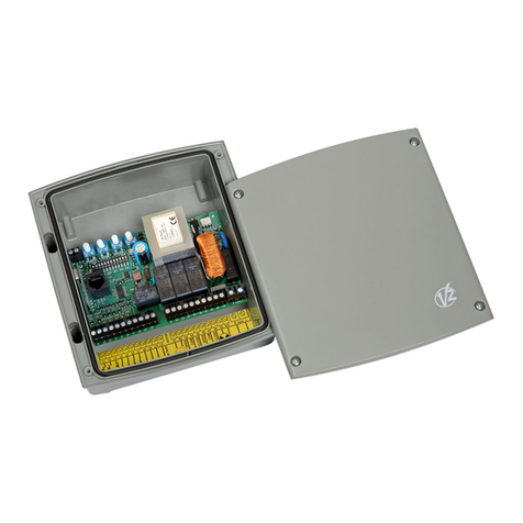
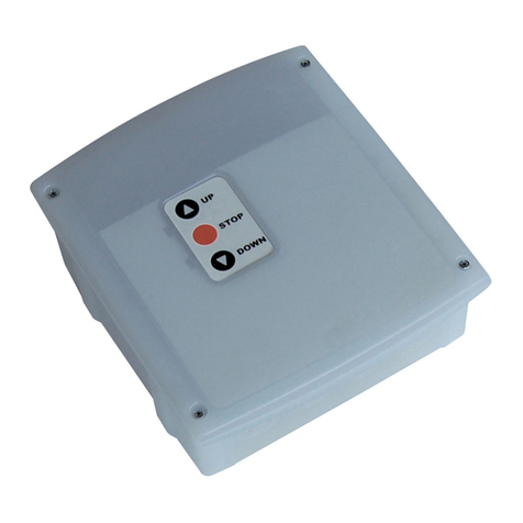
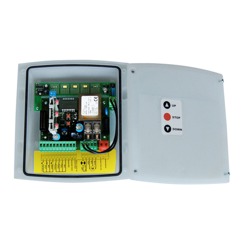
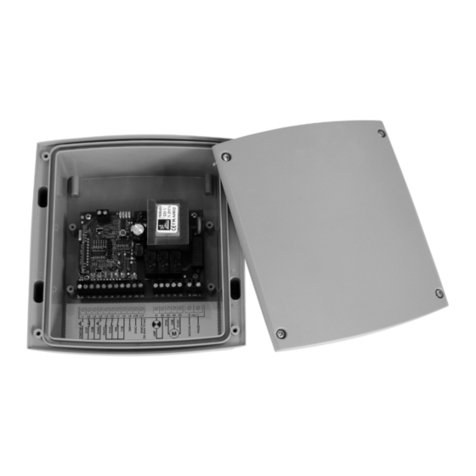
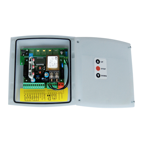
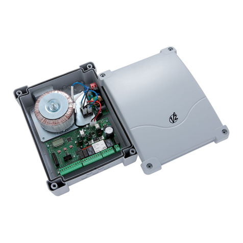
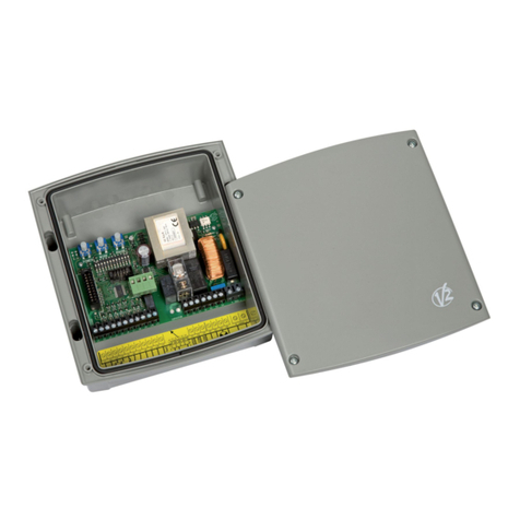
V2 FLEXY2 User manual

Value moves the world
IL 384
EDIZ. 20/03/2014
I
GB
F
E
P
D
NL
PL
FLEXY2
CENTRALE DI COMANDO ANALOGICA PER CANCELLI
A BATTENTE E SCORREVOLI
ANALOGUE CONTROL UNIT FOR LEAF SWING AND
SLIDING GATES
ARMOIRE DE COMMANDE ANALOGIQUE POUR
PORTAILS BATTANTS ET COULISSANTS
CUADRO DE MANIOBRA ANALÓGICO PARA CANCELAS
BATIENTES Y CORREDERAS
QUADRO ANALÓGICO PARA PORTÕES DE BATENTE
E PORTÕES DE CORRER
ANALOGSTEUERUNG FÜR FLÜGELTORE
UND SCHIEBETORE
ANALOGE BESTURINGSEENHEID VOOR DRAAIHEKKEN
EN SCHUIFHEKKEN
PROGRAMATOR ANALOGOWY DO BRAM SKRZYDŁOWYCH I
PRZESUWNYCH

ENGLISH
- 9 -
IMPORTANT REMARKS
For any installation problem please contact our Customer Service
atthenumber+39-0172.812411operatingMondaytoFriday
from8:30to12:30andfrom14:00to18:00.
V2 has the right to modify the product without previous
notice; it also declines any responsibility to damage or
injury to people or things caused by improper use or wrong
installation.
mPlease read this instruction manual very carefully
before installing and programming your control unit.
• Thisinstructionmanualisonlyforqualiedtechnicians,who
specialize in installations and automations.
• Thecontentsofthisinstructionmanualdonotconcerntheend
user.
• Everyprogrammingand/oreverymaintenanceserviceshould
be done only by qualied technicians.
AUTOMATION MUST BE IMPLEMENTED IN COMPLIANCE
WITH THE EUROPEAN REGULATIONS IN FORCE:
EN 60204-1 (Machinerysafety.electricalequipment
ofmachines,part1:generalrules)
EN 12445 (Safeuseofautomatedlockingdevices,test
methods)
EN 12453 (Safeuseofautomatedlockingdevices,
requirements)
• Theinstallermustprovideforadevice(es.magnetotermical
switch)ensuringtheomnipolarsectioningoftheequipment
fromthepowersupply.Thestandardsrequireaseparationof
thecontactsofatleast3mmineachpole(EN60335-1).
• Aftermakingconnectionsontheterminalboard,useone
hoseclamptoxdangerousvoltagewiresneartheterminal
boardandanotherhoseclamptoxsafetylowvoltagewires
usedforaccessoriesconnection;thisway,incaseofaccidental
detachmentofaconductingwire,dangerousvoltagepartswill
notcomeintocontactwithsafetylowvoltageones.
• TheplasticcasehasanIP55insulation;toconnectexibleor
rigidpipes,usepipettingshavingthesameinsulationlevel.
• Installationrequiresmechanicalandelectricalskills,thereforeit
shallbecarriedoutbyqualiedpersonnelonly,whocanissue
theComplianceCerticateconcerningthewholeinstallation
(EECMachineDirective2006/42/CEE,AnnexIIA).
• Theautomatedvehiculargatesshallcomplywiththefollowing
rules:EN13241-1,EN12453,EN12445aswellasanylocal
ruleinforce.
• Alsotheautomationupstreamelectricsystemshallcomplywith
thelawsandrulesinforceandbecarriedoutworkmanlike.
• Thedoorthrustforceadjustmentshallbemeasuredbymeans
ofapropertoolandadjustedaccordingtothemax.limits,
whichEN12453allows.
• Connecttheearthingleadofthemotorstotheelectricitygrid
earth system.
• Observeallnecessaryprecautions(e.g.anti-staticbracelet)for
handlingpartssensitivetoelectrostaticdischarges.
DECLARATION OF CONFORMITY
V2S.p.A.herebydeclarethatFLEXY2productsconformtothe
essentialrequirementsestablishedinthefollowingdirectives:
• 2004/108/CEE(EMCDirectiveinaccordancewithstandards
EN61000-6-2,EN61000-6-3+EN50336)
• 2006/95/CEE(LowVoltageDirectiveinaccordancewith
standardsEN60335-1+EN60335-2-103)
• 99/05/CEE(RadioDirectiveinaccordancewithstandard
EN301489-3)
• DirectiveROHS22011/65/CE
Racconigi,12/01/2013
V2S.p.A.legalrepresentative.egaledellaV2S.p.A.
Cosimo De Falco
TECHNICAL SPECIFICATIONS
Powersupply 230V/50Hz 120V/60Hz
Maxmotorsload 700W 700W
Maxaccessoriesload24V 3W 3W
Workingtemperature -20 ÷ +60 °C -20 ÷ +60 °C
Protectionfuse F1 = 5A delayed F1 = 8A delayed
Dimensions 170 x 185 x 70 mm
Weight 800g
Protection IP55

ENGLISH
- 10 -
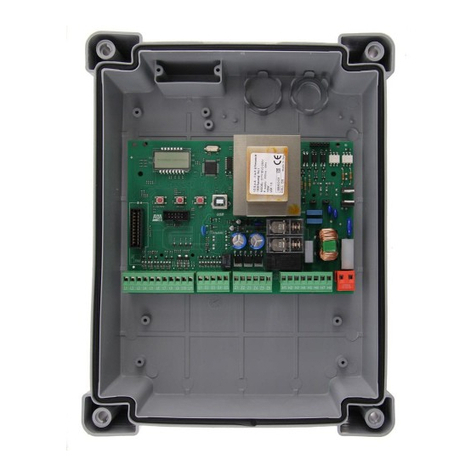
DESCRIPTION OF THE CONTROL UNIT
TheFLEXY2controlunitisaninnovativeV2productguaranteeing
safetyandreliabilityforswinggateautomation.
TheFLEXY2designhasbeenaimedatcreatingaproductwhich
adaptstosuitallneeds,thusobtaininganextremelyversatile
controlunitsatisfyingallthenecessaryrequirementsfora
functionalandefcientinstallation.
• 230V-50Hzor120V-60Hzpowersupplies,dependingonthe
model,for2singlephasemotors(700Wglobal).
• Inputforkeyswitchorpush-button.
• Inputforsafetyphotocell.
• Inputforsafetyedge,capableofhandlingstandardedges
withswitchnormallyclosedandconductiverubberedgeswith
nominalresistanceof8.2kOhms.
• Inputsforopenandcloselimitswitches
• Pre-openingsafetydevicetesting.
• Dip-switchprogrammableoperationallogic.
• Adjustmentofmotorpowerandoperationtimebymeansofa
trimmer.
• Fitted433.92MHzradioreceiver
• Possibilityofsaving240PersonalPasstransmitters
(433.92MHz)
• LEDmonitoringofinputs.
• Courtesylightoutput.
• RJ45connectortoconnectthecontrolunittotheprogrammer
PROG2viastandardnetworkcable(UTP)
• IP55casing.
INSTALLATION
Installationofthecontrolunit,thesafetydevicesandaccessories
mustbeperformedwiththepowersupplydisconnected.
POWER SUPPLY
Thecontrolunitmustbepoweredbymeansofa230V-50Hz
or120V-60Hzpowerline,dependingonthemodel,protected
byadifferentialmagnetothermalswitchincompliancewithlegal
regulations.
ConnectthepowercablestothecontrolunitLand Nterminals.
MOTORS
ThecontrolunitcancontroloneortwoasynchronousACmotors.
Ifthecontrolunitisusedtocontrolonlyonemotor,thenthis
mustbeconnectedtotheterminalsrelatingtomotor1.
Connectthecablesformotor1asfollows:
• OpeningcabletoterminalK3
• ClosingcabletoterminalK5
• CommonreturncabletoterminalK4
• Start-upcapacitorbetweenterminalsK3 and K5
Connectthecablesformotor2(ifpresent)asfollows:
• OpeningcabletoterminalK6
• ClosingcabletoterminalK8
• CommonreturncabletoterminalK7
• Start-upcapacitorbetweenterminalsK6 and K8
PHOTOCELLS
Thecontrolunithasa24VACpowersupplyforphotocellswith
switchnormallyclosed,andcanperformanoperationaltest
beforetostartingthegateopeningprocedure.
Thephotocellcanbeusedwithtwosettings:
1. Photocell always active:
Interventionofthephotocellduringopeningorclosingcauses
thegatetostop.Whenthephotocellrestores,thegatere-
opens completely.
2. Photocell NOT active during opening:
Interventionofthephotocellduringopeningisignored.
Interventionofthephotocellduringclosingcausesthegateto
re-open completely.
Independentlyofthesettingselected,whenthegateispaused
whileopening,thetimecountforanyautomaticre-closurewill
onlystartafterthephotocellrestores.
• Connectthephotocelltransmitterpowercablesbetween
terminals L10 (GND)andL11 (+)onthecontrolunit.
• Connectthephotocellreceiverpowercablesbetweenterminals
L10 (GND)andL9 (+)onthecontrolunit.
• ConnectthephotocellreceiveroutputbetweenterminalsL4
and L8 on the control unit.
SAFETY EDGES
Thecontrolunithasaninputforcontrollingsafetyedges;this
inputiscapableofcontrollingstandardedgeswithswitch
normallyclosedandconductiverubberedgeswithnominal
resistanceof8.2kOhms.
Edgescanbeusedwithtwosettings:
1. Edge always active:
Interventionoftheedgeduringopeningorclosingcauses
inversionofthedirectionofmovementinordertofreethe
bodythatcausedtheedgetointervene.Thegatestopsafter
approx. 3 seconds.
2. Edge NOT active during opening:
Interventionoftheedgeduringopeningisignored.
Interventionoftheedgeduringclosingcausesthegateto
re-open completely.
Independentlyofthesettingsselected,anysubsequentautomatic
re-closurewillbecancelled.
Standard edge with switch normally closed: connecttheedge
cablesbetweenterminalsL5 and L8 on the control unit.
InordertosatisfytherequirementsofstandardEN12978,it
isnecessarytoinstallsafetyedgeswithacontrolunitwhich
constantlymonitorscorrectoperation.Ifcontrolunitsareused
withtheoptionofrunningtestsbymeansofinterruptingthe
powersupply,connectthecontrolunitpowersupplycables
betweenterminalsL10(GND)andL11(+).
Conductive rubber edge:connecttheedgecablesbetween
terminalsL5andL8onthecontrolunit.
mPLEASE NOTE: operational testing on edges is
reserved for standard edges (only if equipped with suitable
control units).
DO NOT enable testing if conductive rubber edges are used
or standard edges used without a suitable control unit for
controlling function.

ENGLISH
- 11 -
COURTESY LIGHT
Thisoutputhasanormally-opencleancontactrelaywhichcloses
forapprox.1secondatthestartofanopeningphase.
Thisswitchmaybeusedtoactivateacourtesylighttimer(max.
load:230V-4A).
TheswitchisonterminalsK1 and K2.
BLINKER
Thecontrolunitprovidesfortheuseofa230V-40Wor
120V-40Wblinkerwithbuilt-inintermittence.
Connect the cables to terminals K9 and K10.
START INPUT
TheSTARTinputispresetforconnectingdeviceswiththeswitch
normally open.
Functiondependsonthemodeofoperationsetbymeansofdip-
switch4.
Step mode
Subsequent Start command cause, in order:
openinggstop gclosure gstop
“Inversion” mode
Startduringopeningcausesclosure.
Startduringclosurecausesopening.
Startwiththegateopenalwaysresultsinclosure;the only case
wherethisdoesnotoccurimmediatelyiswhenautomaticclosure
isenabledandstartwhileopeningisnotaccepted:inthisspecic
case,startmakesthepausetimecountstartfromzero,after
whichthegatewillbere-closed.
InbothmodesitispossibletodisabletheStartcommandduring
gateopeningbymeansof
dip-switch3.
Connectthestartinputcontroldevicecablesbetweenterminals
L1 and L8 on the control unit.
PEDESTRIAN START
Withthegateclosed,thepedestrianstartcommandcausespartial
opening(approx.halfway)ofthegateleafconnectedtomotor1.
Subsequentpedestrianstartcommandswillfunctionaccordingto
steplogic.
Duringapedestriancycle,thestartcommandresultsinthe
completeopeningofbothgateleaves.
Connectthepedestrianstartinputcontroldevicecablesbetween
terminals L2 and L8 on the control unit.
STOP
TheSTOPinputisintendedfordeviceswiththeswitchnormally
closed.
TheSTOPcommandcausestheimmediatestopofthegate.
AsubsequentSTARTcommandactivatesthegateintheopposite
directionofmovement.
IftheSTOPcommandisgivenduringopeningorpause,then
therewillbenosubsequentautomaticre-closure.
Connectthestopinputcontroldevicecablesbetweenterminals
L3 and L8 on the control unit.
LIMIT SWITCH INPUTS
Thecontrolunitisconguredforconnectingaswitchwithswitch
normallyclosed,whichisopenedwhenthegatereachesthe
desired position.
Connectthelimitswitchcablesasfollows:
• ClosinglimitswitchbetweenterminalsL6 and L8
• OpeninglimitswitchbetweenterminalsL7 and L8
EXTERNAL ANTENNA
Itisrecommendedtheexternalantennabeusedinorderto
guaranteemaximumradiocapacity.
Connect the antenna hot pole to terminal A1ofthecontrolunit
andthebraidingtoterminalA2

ENGLISH
- 12 -
ANT
START
STOP
START P.
PHOTO
EDGE
FCA
FCC
COM
POWER
J1 WORK PAUSE DELAY
1 2 3 4 5 6 7 8 9 10 11 12
START START P.
STOP
PHOTO
L1 L2
A1 A2
L3 L4 L5 L6 L7 L8 L9 L10 L11 K1 K2 K3 K4 K5 K6 K7 K8 K9 K10 N Lmains
EDGE
FCA
FCC
overload
mains
F1
L1
PROG.RX
RJ45
(Photo / Edge Test)
1
COURTESY
LIGHT
CONTACT
2
ELECTRICAL CONNECTION
mPLEASE NOTE: If not used, the normally closed inputs (STOP, PHOTO, EDGE, FCA, FCC) must be jumpered with the
commands common line COM (-)

ENGLISH
- 13 -
A1 Antenna
A2 Antenna shield
L1 Openingcommandforastandardconnectiondevice
withswitchnormallyopen.
L2 Pedestrianopeningcommandforastandard
connectiondevicewithswitchnormallyopen.
L3 STOPcommand.N.C.switch
L4 Photocell.N.C.switch
L5 Edge.SwitchN.C.orresistiverubberedge
L6 Limitswitchopen.N.C.switch
L7 Limitswitchclosed.N.C.switch
L8 Commandscommon(-)line
L9 - L10 24VACpoweroutputforphotocellsandother
accessories
L10 - L11 PowersupplyforfunctionaltestTXphotocell
K1 - K2 Courtesylighttimeractivationswitch
K3 Motor1open
K4 Motor1common
K5 Motor1close
K6 Motor2open
K7 Motor2common
K8 Motor2closed
K9 - K10 230V - 40W / 120V - 40W blinker
N230V/120Vpowersupply-neutral
L230V/120Vpowersupply-phase
CABLE GLAND ASSEMBLY
Thecasingcanaccept4cableglandsinthespecialeasy-break
housings.
Thetypeofcableglandisindicatedinthegure.
mPLEASE NOTE:
• Removetheelectroniccircuitboardbeforedrillthecasing.
• Drillthecontainerusingasuitablysizedcutter,accordingtothe
dimensionsofthecablegland.
• Fixthecableglandsusingthespecialnuts.
PG9 - PG11
PG9 - PG11 - PG16

ENGLISH
- 14 -
DIP FUNCTION SETTING DESCRIPTION
1Pre-ashing ON Disabled Theblinkerisswitchedonwhenthemotorsarestarted
OFF Enabled Theblinkerisswitchedonfor2secondsbeforethemotorsarestarted
2Automatic closure
ON Enabled ThegateisclosedautomaticallyaftertheperiodoftimesetbythePAUSE
trimmer
OFF Disabled Oncompletionoftheopeningstep,thegateremainsopen.Itisnecessaryto
instructclosurewithanotherSTARTcommand
3Startduring
opening
ON Not accepted AnySTARTcommandissuedduringopeningisignored
OFF Accepted AnySTARTcommandissuedduringopeningisaccepted
4Operationallogic
ON Inversion Startduringopeningcausesclosure.
Startduringclosurecausesopening.
OFF Step Commandssubsequenttostartingcause,inorder:
open gstop gclose gstop...
5Slowdown
ON Enabled Attheendofeachopeningandclosingstep,themotorsslowdowninorder
toavoidnoisyclosureandbouncing.
OFF Disabled
6Startoff ON Disabled Atthestartofeachopeningandclosingstep,themotorsarestartedat
maximumpower
OFF Enabled
7Anti-slip
ON Disabled ThetimeusedforopeningorclosurewillalwaysbethevaluesetbytheWORK
trimmer,evenifthepreviousoperationhasbeeninterruptedbeforetheexpiry
ofsuchtime.
OFF Enabled Whenanopening(orclosing)operationisinterruptedbeforeexpiryofthe
settime(forexampleduetotheinterventionofoneofthesafetydevicesor
duetoastartcommand),thedurationofthesubsequentclosing(oropening)
operationwillnotbethatsetbytheWORKtrimmer,butwillbeequaltothe
timeeffectivelyelapsed,plusashortsupplementaltimeinordertocompensate
fortheinertiaofthegate.
8Photocell
ON Alwaysactive Interventionofthephotocellduringopeningorclosingcausesthegateto
stop.Whenthephotocellrestores,thegatere-openscompletely.
OFF NOTactiveduring
opening
Interventionofthephotocellduringopeningisignored.Interventionofthe
photocellduringclosingcausesthegatetore-opencompletely.
9Photocell test
ON Enabled Thecontrolunitperformsaphotocelloperationaltestbeforestartingeach
openingorclosingoperation.Ifthephotocellsarenotoperatingcorrectly,the
gatedoesnotbegintomoveandthelightashesforapprox.8seconds.
PLEASE NOTE: connect the photocell TX correctly
OFF Disabled
10 Safetyedgetype
ON Conductive rubber
edge
Selectthisoptionifusingconductiverubberedgeswithnominalresistanceof
8K2.
OFF Standard or optical
edge
Selectthisoptionifusingstandardedgeswithswitchnormallyclosedor
opticaledges.
11 Safetyedge
ON Alwaysactive Interventionoftheedgeduringopeningorclosingcausesinversionofthe
directionofmovementinordertofreethebodythatcausedtheedgeto
intervene.Thegatewillbestoppedafterapprox.3seconds.
OFF NOTactiveduring
opening
Interventionoftheedgeduringopeningisignored.Interventionoftheedge
duringclosingcausesthegatetobere-openedcompletely.
12 Safetyedgetest
ON Enabled Thecontrolunitperformsanoperationaltestontheedgesbeforestarting
eachopeningorclosingoperation.Iftheedgesarenotoperatingcorrectly,the
gatedoesnotbegintomoveandthelightashesforapprox.8seconds.
DO NOT enable testing if conductive rubber edges are used or standard
edges are used without a suitable control unit for controlling function.
OFF Disabled
PROGRAMMING THE OPERATIONAL LOGIC
Itispossibleforthecontrolunittouseseveraldifferentoperationallogicstates,bysimplymovingthedip-switcheslocatedonthecard.
Thefunctionsassociatedwitheachindividualdip-switcharelistedbelow.

ENGLISH
- 15 -
ADJUSTMENT OF THE POWER AND
OPERATIONAL TIMES
Thepowerandoperatingtimesmaybeadjustedbymeansof4
trimmers located on the control unit:
mPLEASE NOTE: it is recommended that operating times
be set with the slow down function disabled (DIP 5 OFF).
mWARNING: the adjustment of times has to be made
when the gate is still
CONTROL UNIT INDICATORS (LEDs)
ThehighlightedboxesindicatethestateoftheLEDswhenthegateisresting.
LED ON OFF
START STARTinputclosed STARTinputopen
START P. STARTP.inputclosed STARTP.inputopen
STOP STOPinputclosed STOPinputopen
PHOTO PHOTOinputclosed PHOTOinputopen
EDGE Standard edge
EDGEinputclosed(edgenotpressed) EDGEinputopen(edgepressed)
Resistive rubber edge
EDGEinputclosed(edgepressed) EDGEinputopen(fault)
EdgeNOpressed:8K2betweenEDGEinputand
common(-)
FCA Openinglimitswitchclosed Openinglimitswitchopen
FCC Closinglimitswitchclosed Closinglimitswitchopen
mains Controlunitpowered-up ControlunitNOTpowered-up
overload Accessorypowersupplyoverload Accessorypowersupplywithinnormaloperationallimits
POWER: motorpower.
WORK: motoroperatingtime
J1closed=2-50seconds
J1opened=2-120seconds
PAUSE: pausetimebeforeautomaticre-closure
(2-150seconds).
DELAY: timedelaybetweenthetwogateleaves
(0-90seconds).
POWER
MIN MAX
WORK 120”
30”
2”
2”
90”
WORK 50”
18”
2”
2”
45”
PAUSE 150”
30”
2”
2”
90”
DELAY 90”
15”
0
0
45”
J1 closed J1 opened
J1 opened J1 closed

ENGLISH
- 16 -
STORING OF THE TRANSMITTERS
• KeepPROG.RXpresseduntiltheledL1lightens
• Releasethepush-button,theledswitchesoffanditsendsout
asequenceofsingleashingsfor5seconds:thenumberof
shortashingsshowstheselectedchannel
• ToselectthefurtherchannelspressandreleasethePROG.RX
push-buttonwithin5seconds,theledchangestypeofashing
accordingtothefollowingtable:
FULL ERASING of the TRANSMITTERS
Toperformafullerasingofthetransmittersstoredinmemorydo
thefollowing:
• Switchoffthepowersupplyofthecontrolunit,
• PressandholdpressedthePROG.RXkeyofthereceiver
• Atthesametimeturnonthepowersupplyagain.TheL1led
goeson
• ReleasethePROG.RXkey:theledL1remainsonforthe
durationoftheerasingphase(about5seconds)
• WhentheledL1turnsofftheerasingprocedureiscomplete
andthecontrolunitisreadyforanewprogramming
To perform a partial code erasing the PROG2 portable
programmer is required
ROLLING CODE FUNCTION
ItispossibletoenableandtodisabletheROLLINGCODEfunction
(normallydisabled)
• PressPROG.RXpush-button,holdingitfor8seconds.
• L1ledwillswitchoffafter8seconds.Releasethepush-button.
• L1ledstartsasequenceofashingfor5seconds:
Singleashings g ROLLINGCODEisdisabled
Doubleashings g ROLLINGCODEisenabled
• TomodifytheparameterspressthePROG.RXpush-button
within5secondsaftertherstashingofthesequence;L1led
willashaccordingtothenewparameters.
SUBSITUTIVE TRANSMITTER
Thesubstitutivetransmitter,generatedonlybymeansof
WINPPCL,allowstoreplacebyradioatransmitterstoredinthe
receiver.
Asingletransmissionwiththespeciallyprogrammed
SUBSTITUTIVETX,nearbythereceiver,replacesthetransmitter
codewiththenewone.
RepeattheprocesswithallkeysoftheSUBSTITUTIVETX.
Example:MemorizedTXAtransmitter
Itispossibletomakethreereplacementsmaximumpercode,so
forTXAyoucannd:
TXBreplacesTXA(TXAisnolongeroperative)
TXCreplacesTXB(TXBisnolongeroperative)
TXDreplacesTXC(TXCisnolongeroperative)
• Choosethechannelyouwanttomemorizeandwithin5
secondspressandholdthepush-buttonofthetransmitter.
• TheledL1switchesoffanditswitchesonagain:thismeans
that the code has been memorized.
• Thedevicewillwaitforafurthercodetomemorizefora
maximumtimeof5seconds.
SELECTED
CHANNEL
FUNCTION N° Impulses
PROG.RX
Flashing
single double triple quadruple
CHANNEL1 START 1•
CHANNEL2 PEDESTRIANSTART 2••
CHANNEL3 STOP 3•••
CHANNEL4 COURTESYLIGHT 4••••
Other manuals for FLEXY2
1
Table of contents
Other V2 Control Unit manuals