Table of Figures
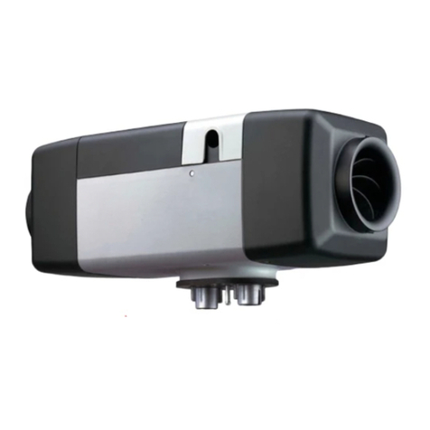
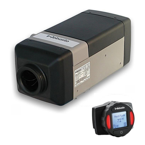
Figure 1: Air Top Evo 40/55 Air Heater .................................................................................................................................. 11
Figure 2: Air Top Evo 40/55 .................................................................................................................................................. 11
Figure 3: Drive Unit................................................................................................................................................................ 11
Figure 4: Heat Exchanger....................................................................................................................................................... 12
Figure 5: Evaporator Mount with........................................................................................................................................... 12
Figure 6: Evaporator Mount with........................................................................................................................................... 12
Figure 7: Glow Plug ............................................................................................................................................................... 13
Figure 8: Exhaust Temperature Sensor ................................................................................................................................... 13
Figure 9: Overheat Temperature Sensor................................................................................................................................. 14
Figure 10: Control Unit.......................................................................................................................................................... 14
Figure 11: Fuel Pump............................................................................................................................................................. 15
Figure 12: Components Required .......................................................................................................................................... 25
Figure 13: Characteristic resistance value of a PT 2000 Overheat Temperature Sensor in the temperature range 10 °C to 30 °C
.............................................................................................................................................................................................. 32
Figure 14: Connector Assignment on Control Unit ................................................................................................................ 38
Figure 15: Wiring Diagram for Air Top Evo 40 / 55, 12V / 24V with rheostat .......................................................................... 39
Figure 16: Wiring Diagram for Air Top Evo 40 /55, 12V/24V with MultiControl (MC04) control element ............................... 40
Figure 17: Wiring diagram for Air Top Evo 40 / 55, 12V / 24V with Smartemp....................................................................... 41
Figure 18: Connection Diagram for Air Top 40 / 55 with Air Top Evo MultiControl (MC04) control element......................... 42
Figure 19: Installation Position of Fuel Pump DP 42................................................................................................................. 47
Figure 20: Fuel Filter, installation position and flow direction ................................................................................................. 48
Figure 21: Permissible installation position of.......................................................................................................................... 49
Figure 22: Permissible installation position of exhaust pipe end .............................................................................................. 50
Figure 23: Remove the fastening plate on the fuse holder ...................................................................................................... 50
Figure 24: Fuse Holder, installation position............................................................................................................................ 50
Figure 25: Rheostat ................................................................................................................................................................ 51
Figure 26: Disconnect the Plug ............................................................................................................................................... 51
Figure 27: Installation example for heater in recirculated air mode.......................................................................................... 52
Figure 28: External room temperature sensor ......................................................................................................................... 55
Figure 29: Removing/fitting housing parts .............................................................................................................................. 56
Figure 30: Replace control unit, Overheat Temperature Sensor, .............................................................................................. 58
Figure 31: Cable for exhaust temperature sensor.................................................................................................................... 59
Figure 32: Sealing surface of exhaust temperature sensor....................................................................................................... 59
Figure 33: Top view of heat exchanger ................................................................................................................................... 60
Figure 34: Replacing evaporator mount, glow plug,................................................................................................................ 62
6
Air Top Evo 40 / Air Top Evo 55 Service Manual
