Weco Multi Power 204T User manual

Cod. 006.0001.1420
08/09/2021 V.2.12
Multi Power 204T
Instruction manual
ENG
Translation of original instructions

WELD THE WORLD
Cod. 006.0001.1420
08/09/2021 V.2.12 Multi Power 204T
2
ENGLISH

WELD THE WORLD
Cod. 006.0001.1420
08/09/2021 V.2.12
Multi Power 204T
3
ENGLISH
INDEX
1 INTRODUCTION.......................................................................................................................................... 4
1.1 PRESENTATION.......................................................................................................................................... 5
2 INSTALLATION .......................................................................................................................................... 6
2.1 CONNECTIONS TO THE MAINS POWER SUPPLY .................................................................................. 6
2.2 FRONT PANEL............................................................................................................................................. 6
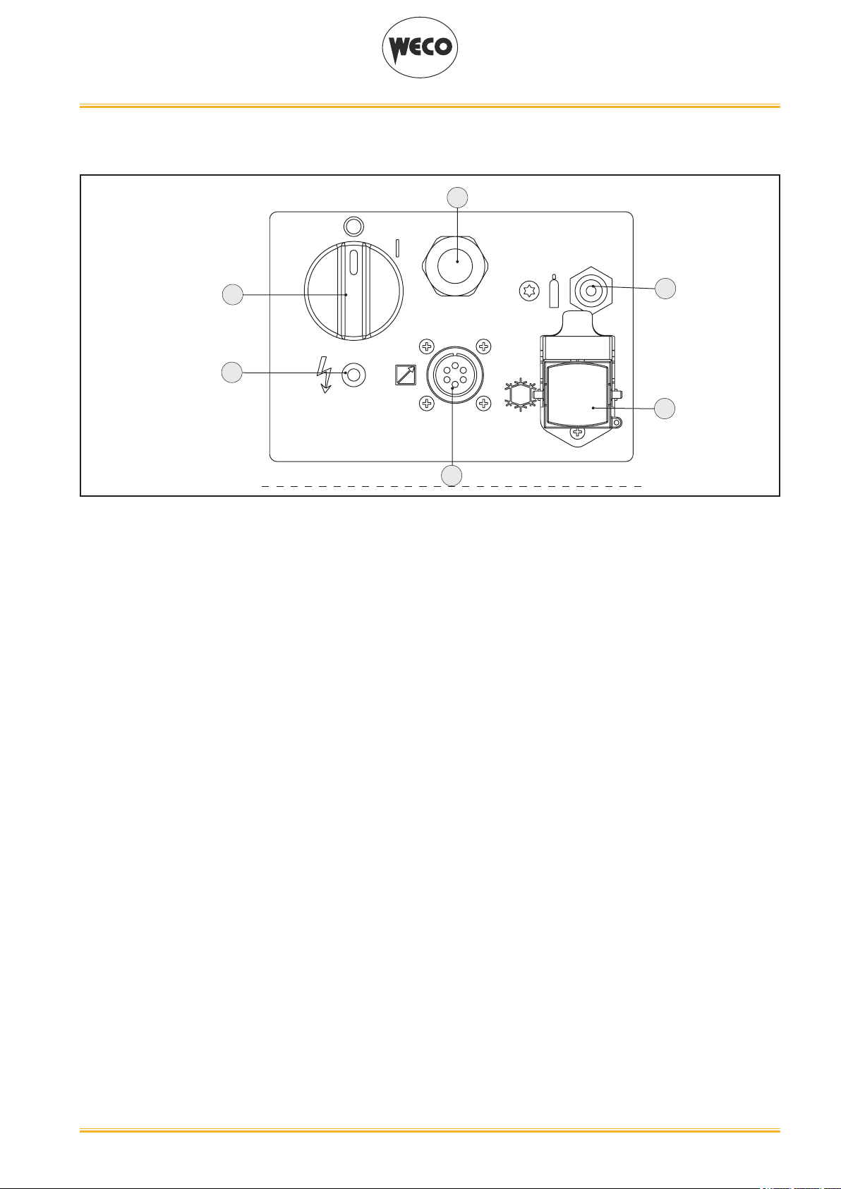
2.3 REAR PANEL............................................................................................................................................... 7
2.4 PREPARING FOR MMA WELDING............................................................................................................. 8
2.5 PREPARING FOR TIG WELDING ............................................................................................................... 9
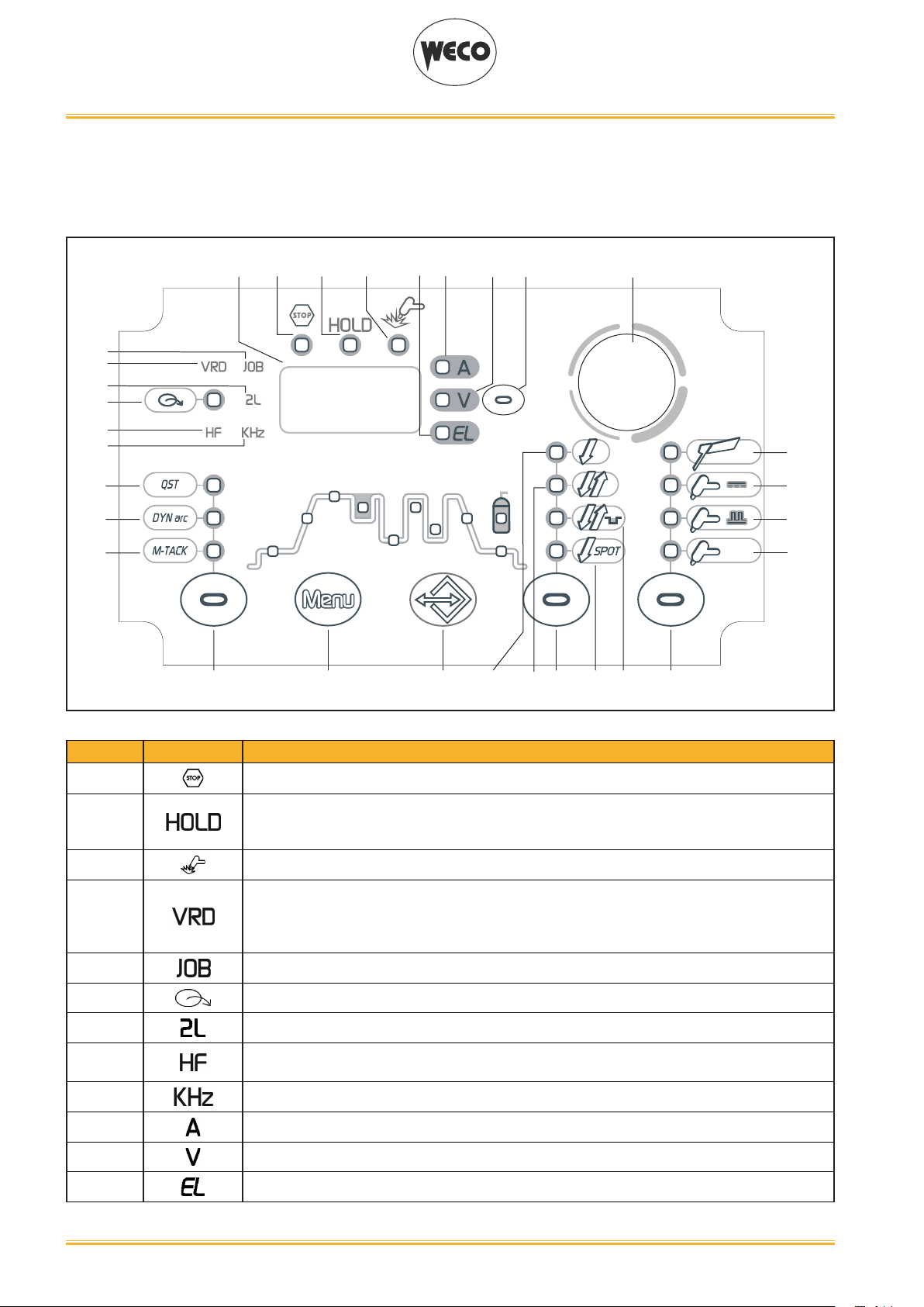
3 USER INTERFACE .................................................................................................................................... 10
4 UNIT POWER-UP ...................................................................................................................................... 13
5 RESET (LOAD FACTORY SETTINGS)..................................................................................................... 14
6 SET-UP (INITIAL SET-UP OF THE WELDING POWER SOURCE) ......................................................... 15
6.1 TORCH LOADING ..................................................................................................................................... 17
7 ALARM MANAGEMENT ........................................................................................................................... 18
8 DERATING................................................................................................................................................. 20
9 MMA WELDING......................................................................................................................................... 21
9.1 MMA WELDING - FIRST LEVEL MENU .................................................................................................... 21
9.2 MMA WELDING - SECOND LEVEL MENU ............................................................................................... 23
9.3 MMA WELDING - SPECIAL FUNCTIONS ................................................................................................. 25
10 DC TIG WELDING ..................................................................................................................................... 26
10.1 DC TIG WELDING - FIRST LEVEL MENU ................................................................................................ 26
10.2 TIG DC WELDING - SECOND LEVEL MENU ........................................................................................... 31
10.3 TIG DC WELDING - SPECIAL FUNCTIONS MENU ................................................................................. 34
11 TORCH TRIGGER PROCEDURE ............................................................................................................. 38
11.1 2 STROKE SPOT - Q-SPOT FUNCTION .................................................................................................. 44
12 JOBS MANAGEMENT .............................................................................................................................. 49
12.1 SAVING A JOB ........................................................................................................................................... 49
12.2 DELETING A JOB ...................................................................................................................................... 50
12.3 LOADING A JOB ........................................................................................................................................ 51
12.4 SELECTING JOBS USING THE TORCH BUTTONS ................................................................................ 51
13 TECHNICAL DATA .................................................................................................................................... 52
13.1 MULTI POWER 204T ................................................................................................................................. 52
14 WIRING DIAGRAM.................................................................................................................................... 54
14.1 TORCH CONNECTOR (front panel) .......................................................................................................... 55
14.2 REMOTE CONTROL CONNECTOR (back panel)..................................................................................... 55
15 SPARES..................................................................................................................................................... 56
15.1 MULTI POWER 204T ................................................................................................................................. 56
15.2 TORCH CONNECTORS COMPLETE KIT................................................................................................. 58

WELD THE WORLD
Cod. 006.0001.1420
08/09/2021 V.2.12 Multi Power 204T
4
ENGLISH
1 INTRODUCTION
IMPORTANT!
This handbook must be consigned to the user prior to installation and commissioning of the unit.
Read the "General prescriptions for use" handbook supplied separately from this handbook before
installing and commissioning the unit.
The meaning of the symbols in this manual and the associated precautionary information are given in
the "General prescriptions for use”.
If the "General prescriptions for use" are not present, it is mandatory to request a replacement copy
from the manufacturer or from your dealer.
Retain these documents for future consultation.
LEGEND
DANGER!
This pictogram warns of danger of death or serious injury.
WARNING!
This pictogram warns of a risk of injury or damage to property.
CAUTION!
This pictogram warns of a potentially hazardous situation.
INFORMATION!
This pictogram gives important information concerning the execution of the relevant operations.
This symbol identies an action that occurs automatically as a result of a previous action.
This symbol identies additional information or a reference to a dierent section of the manual
containing the associated information.
§ This symbol identies a reference to a chapter of the manual.
*1 The symbol refers to the associated numbered note.
NOTES
The gures in this manual are purely guideline and the images may contain dierences with respect to
the actual equipment to which they refer.

WELD THE WORLD
Cod. 006.0001.1420
08/09/2021 V.2.12
Multi Power 204T
5
ENGLISH
1.1 PRESENTATION
Multi Power 204T is an inverter DC TIG/MMA portable welding power source.
The sturdiness of the components of this unit makes it a reliable working companion for workshop and
outdoor applications.
The available DC TIG functions and digital control make this unit ideal for maintenance, building con-
struction, and light metalwork.
In MMA welding the Hot Start and Arc Force functions are adjustable and they allow improved arc strik-
ing, a atter bead and more uniform weld.
The Anti Sticking function makes it possible to detach the electrode rapidly from the workpiece in the
event of accidental sticking.
Up to 4,00mm diameter electrode welding is possible in MMA.
The power source is designed to guarantee safety and exibility through the following features:
OVERCUT: in case of over-voltage in the supply line, the supply to the power source is cut o.
The overcut protection protects electronic parts of the machine against damage caused by voltage
surges.
CURRENT AUTO-CALIBRATION: the power source works at a supply voltage ranging between
115V~±15%/50-60Hz and 230V~±15%/50-60Hz.
The maximum value of the adjustable welding current is automatically limited based on the supply volt-
age measured when the power source is switched on.
DERATING: Derating limits current during welding when supply voltage drops below the limit value of
190Vac.
This limits current input so as not to overload the inverter and keeps the welding arc stable.
FANS: Fan speed varies based on power source internal temperature measured by thermal sensors.
This function brings the following improvements:
- reduction of noise.
- reduction of dust extracted (cleaner equipment, less maintenance).
The welding modes and procedures available are those indicated in the table.
MODE PROCEDURE
MMA
TIG CONTINUOUS
2 STROKE LIFT-ARC (2T)
+ 2 STROKE + HF (2T HF)
4 STROKE LIFT-ARC (4T)
TIG PULSED
+ 4 STROKE + HF (4T HF)
4 STROKE BI-LEVEL (4T B-LEVEL)
+ 4 STROKE BI-LEVEL + HF (4T B-LEVEL HF)
SYNERGIC TIG
2T SPOT
+ 2T SPOT + HF

WELD THE WORLD
Cod. 006.0001.1420
08/09/2021 V.2.12 Multi Power 204T
6
ENGLISH
Accessories that can be connected to the unit:
• manual remote control for remote adjustment of the welding current.
• foot-pedal remote control for TIG torch arc striking and remote adjustment of welding current.
• UP/DOWN torch or torch with potentiometer.
• liquid cooler for TIG torches.
2 INSTALLATION
DANGER!
Lifting and positioning
Read the warnings highlighted by the following symbols in the “General prescriptions for use”.
2.1 CONNECTIONS TO THE MAINS POWER SUPPLY
The characteristics of the mains power supply to which the equipment shall be connected are given in
the chapter entitled “12 TECHNICAL DATA” on page 48.
The machine can be connected to motor-generators provided their voltage is stabilised.
Connect/disconnect the various devices with the machine switched o.
2.2 FRONT PANEL
32 4 1
○ Negative pole welding socket.[Item 1].
○ Positive pole welding socket.[Item 2].
○ Connector for logic signals of TIG torch.[Item 3].
○ Connector for gas feed hose: Torch power source [Item 4].

WELD THE WORLD
Cod. 006.0001.1420
08/09/2021 V.2.12
Multi Power 204T
7
ENGLISH
2.3 REAR PANEL
1
5
3
6
2
4
○ Welding power source ON/OFF switch [Item 1].
○ Remote control connector [Item 2].
○ Connector for gas feed hose [Item 3]
• cylinder-generator
○ Power cable. [Item 4].
• Total length (including internal part): 2.5 m;
• Number and cross section of wires: 3 x 2.5 mm2
• Type of plug supplied: Schuko
○ Warning LED for overcut protection triggering [Item 5].
○ Pre-arrangement for the supply socket of the cooling unit (purchasing and installing the relative
kit) [Item 6].

WELD THE WORLD
Cod. 006.0001.1420
08/09/2021 V.2.12 Multi Power 204T
8
ENGLISH
2.4 PREPARING FOR MMA WELDING
1. Set the welding power source ON/OFF switch to “O” (unit o).
2. Plug the power cable plug into a mains socket.
3. Choose the electrode based on the type of material and thickness of the workpiece to be welded.
4. Insert the electrode in the electrode holder.
5. Connect the electrode holder clamp plug to the following welding socket: Positive pole welding
socket.
6. Connect the earth clamp plug to the following welding socket: Negative pole welding socket.
7. Connect the earth clamp to the workpiece being processed.
DANGER!
Electric shock hazard!
Read the warnings highlighted by the following symbols in the “General prescriptions for use”.
8. Set the welding power source ON/OFF switch to “I” (unit on).
9. Select the following welding mode on the user interface: MMA
10. Set the required welding parameter values on the user interface.
When the remote control [RC] is connected and enabled, the welding current can be adjusted.
The system is ready to start welding.
REAR VIEW FRONT VIEW
RC
REMOTE
CONTROL

WELD THE WORLD
Cod. 006.0001.1420
08/09/2021 V.2.12
Multi Power 204T
9
ENGLISH
2.5 PREPARING FOR TIG WELDING
1. Set the welding power source ON/OFF switch to “O” (unit de-energized).
2. Plug the power cable plug into a mains socket outlet.
3. Connect the gas hose from the welding gas cylinder to the rear gas connection.
4. Open the cylinder gas valve.
5. Connect the gas hose of the welding torch to the front gas connection.
6. Connect the electrode holder clamp plug to the following welding socket: Negative pole welding
socket.
7. Choose the electrode based on the type of material and thickness of the workpiece to be welded.
8. Insert the electrode in the TIG torch.
9. Connect the earth clamp plug to the following welding socket: Positive pole welding socket.
10. Connect the earth clamp to the workpiece being processed.
11. Set the welding power source ON/OFF switch to “I” (unit powered).
12. Select the following welding mode on the user interface: DC TIG
13. Press the torch trigger with the torch well clear of any metal parts. This serves to open the gas
solenoid valve without striking the welding arc.
14. Use the ow control valve to adjust the ow of gas as required while the gas is owing out.
15. Set the required welding parameter values on the user interface.
When the remote control pedal is connected and the relative locking screw is tightened the
welding current will vary in relation to the pressure exerted on the pedal.
The system is ready to start welding.
REAR VIEW FRONT VIEW
RC
REMOTE
CONTROL

WELD THE WORLD
Cod. 006.0001.1420
08/09/2021 V.2.12 Multi Power 204T
10
ENGLISH
3 USER INTERFACE
MULTI POWER 204T
SYN
L1 L2 L3
L15
L13
L14
L10 L11L12
L29 L28
D1 S1
S2
E1
L6
S3 S4 S5 S6
L9
L8
L4
L5
L7
L33
L31
L32
L30
L26 L27
L18
L22
L20
L21
L23
L24
L25
L17
L16
L19
CODE SYMBOL DESCRIPTION
L1 This LED illuminates to show an anomaly in the operating conditions.
L2
Illuminates to show the last voltage and current values measured during welding.
The value appears on the display D1:
The “HOLD” function is cleared when a new weld is started or when any setting is changed.
L3 This LED illuminates to conrm the presence of power on the output sockets.
L4
Illumination shows that the following function has been activated: VRD (reduced output volt-
age).
The no-load voltage between the welding sockets is switched from U0 to Ur (see technical
data).
L5 Illuminates to show that a previously saved JOB has been loaded.
L6 This LED indicates that the current reference is set up by the remote control.
L7 When this LED illuminates the 2nd level Menu parameter is shown.
L8 Illumination shows that the following function has been activated: HIGH FREQUENCY ARC
STRIKE (HF)
L9 Illuminates to show a value in the following unit of measurement: KILOHERTZ
L10 Illuminates to show a value in the following unit of measurement: AMPERES
L11 Illuminates to show a value in the following unit of measurement: VOLTS
L12 Illumination shows that the following parameter can be displayed: ELECTRODE TYPE

WELD THE WORLD
Cod. 006.0001.1420
08/09/2021 V.2.12
Multi Power 204T
11
ENGLISH
L13 Illumination shows that the following parameter can be set: Q-START
L14 Illumination shows that the following parameter can be set: DYNAMIC ARC
L15 Illumination shows that the following parameter can be displayed: MULTI TACK
L16 Illumination shows that the following parameter can be set: STARTING CURRENT (%/A)
L17 Illumination shows that the following parameter can be set: SLOPE UP (s)
L18 Illumination shows that the following parameter can be set: WELDING CURRENT (A)
L19 Illumination shows that the following parameter can be set: SECOND CURRENT B-LEVEL (%)
L20 Illumination shows that the following parameter can be set: BASE CURRENT (A)
L21 Illumination shows that the following parameter can be set: PEAK TIME (s)
L22 illumination shows that the following parameter can be set: BASE TIME(s)
L21 + L22 illumination shows that the following parameter can be set: PULSED CURRENT FREQUENCY
(Hz/kHz)
L23 illumination shows that the following parameter can be set: SLOPE DOWN (s)
L24 illumination shows that the following parameter can be set: STARTING CURRENT (%/A)
L25 illumination shows that the following parameter can be set: POST-GAS (s)
L26 Illumination shows that the following function has been activated: 2 stroke procedure.
L27 Illumination shows that the following function has been activated: 4 stroke procedure.
L28 Illumination shows that the following function has been activated: 4 stroke Bi-level procedure
L29 Illumination shows that the following function has been activated: 2 stroke spot procedure
(SPOT).
L30 This LED illuminates to show that the following welding mode is selected: MMA
L31 This LED illuminates to show that the following welding mode is selected: TIG DC CONTINU-
OUS
L32 This LED illuminates to show that the following welding mode is selected: PULSED DC TIG
L33
This LED illuminates to show that the following welding mode is selected: SYNERGIC PULSED
TIG
When this is on, it means that the synergic mode is active and that the operator can set just the
welding current while the other parameters are automatically regulated by the machine. The
synergy is optimised by angle welding.

WELD THE WORLD
Cod. 006.0001.1420
08/09/2021 V.2.12 Multi Power 204T
12
ENGLISH
D1
Data setting: The display shows the acronym of the parameter to be set.
Welding: The display shows the eective amperes value during welding.
HOLD function: The display shows the average current value measured over the entire welding
period (excluding the starting and ending slopes).
E1 Data setting: The encoder sets the value of the selected parameter.
Welding: The encoder sets the value of the following parameter: WELDING CURRENT
S1
Parameters/functions setting: This button selects the parameter to be shown on the following
display: D1
Possible choices:
(A) Preset welding current
(V) No-load voltage
(EL) Preset type of electrode
Welding: This button selects the parameter to be shown on the following display: D1
Possible choices:
(A) Eective welding current
(V) Eective welding voltage
HOLD function: This button selects the parameter to be shown on the following display: D1
Possible choices:
(A) Average welding current
(V) Average welding voltage
S2
TIG Mode: Press the button to select the parameter to be set.
Possible selections: Q-START, DYNAMIC ARC, MULTI TACK
MMA mode: DYNAMIC ARC
S3
Press and release: the button selects the rst level menu parameters.
Hold down for 3 seconds: the button opens the second level menu. When in the menu, press
and release the button to select the parameters.
Keep the button pressed while powering on the power source: the button opens the SETUP
menu.
S4 Press and release: the button opens the JOBs upload menu.
Hold down for 3 seconds: the button opens the JOBs save and delete menu.
S5 TIG DC / TIG AC mode: This button selects the torch trigger procedure.
MMA mode: Press the button to show the selected electrode type for MMA welding.
S6 This button selects the welding mode.

WELD THE WORLD
Cod. 006.0001.1420
08/09/2021 V.2.12
Multi Power 204T
13
ENGLISH
4 UNIT POWER-UP
Set the welding power source ON/OFF switch to “I” to switch on the unit.
FX.X The message appears on the following display: D1.
x.x= software version
First power-up or power-ups following a RESET procedure
The welding power source sets up for welding with the factory preset values.
Subsequent power-ups
The welding power source sets up for welding in the latest stable welding conguration that was active
at the time of power-o.
The power source works at a supply voltage ranging between 115V~±15%/50-60Hz and 230V~±15%/50-
60Hz.
The maximum value of the adjustable welding current is automatically limited based on the supply vol-
tage measured when the power source is switched on.
SUPPLY VOLTAGE CURRENT RANGE THAT CAN BE
SET (MMA)
CURRENT RANGE THAT CAN BE
SET (TIG)
115 V~ ±15 % / 50 - 60 Hz 10 A – 115 A 5 A - 115 A
230 V~ ±15 % / 50 - 60 Hz 10 A – 180 A 5 A - 200 A

WELD THE WORLD
Cod. 006.0001.1420
08/09/2021 V.2.12 Multi Power 204T
14
ENGLISH
5 RESET (LOAD FACTORY SETTINGS)
SYN
L1 L2 L3
L15
L13
L14
L10 L11L12
L29 L28
D1 S1
S2
E1
L6
S3 S4 S5 S6
L9
L8
L4
L5
L7
L33
L31
L32
L30
L26 L27
L18
L22
L20
L21
L23
L24
L25
L17
L16
L19
FAC
AA
ACTIVATION ACTIVATION
The reset procedure involves complete restoration of the default values, parameters and memory set-
tings set in the factory.
All memory locations will be reset and hence all your personal welding settings will be lost!
The reset procedure is useful in the following cases:
- Too many changes made to the welding parameters so user nds it dicult to restore defaults.
- Unidentied software problems that prevent the welding power source from functioning correctly.
A
○ Set the welding power source ON/OFF switch to “O” to switch the unit o.
○Keeping both the S2 and S6 buttons pressed, set the generator power source
switch to “I” to turn on the equipment [ SIMULTANEOUS ACTIONS]
○Press both buttons S2 and S6
FAC: The message will appear on display D1
- Wait for the memory clear procedure to terminate. This action will automatically close the
menu.

WELD THE WORLD
Cod. 006.0001.1420
08/09/2021 V.2.12
Multi Power 204T
15
ENGLISH
6 SET-UP (INITIAL SET-UP OF THE WELDING POWER SOURCE)
SYN
L1 L2 L3
L15
L13
L14
L10 L11L12
L29 L28
D1 S1
S2
E1
L6
S3 S4 S5 S6
L9
L8
L4
L5
L7
L33
L31
L32
L30
L26 L27
L18
L22
L20
L21
L23
L24
L25
L17
L16
L19
SEt
AC
ACTIVATION/
SELECTION EXIT
B
SETTING
A
○ Set the welding power source ON/OFF switch to “O” to switch the unit o.
○Holding the S3 button down, turn the power source switch to “I” to start the equipment. [
SIMULTANEAOUS ACTIONS]
Set : The message will appear for a few seconds on display D1.
○Press the S3 button to conrm.
The value relative to the selected setting will appear on display D1.
B○Using the encoder E1 , edit the value of the selected setting.
C
○Exit with conrmation
- Press any button (except S3) for example S4 to save the setting and quit the
menu.
Tab. 1 - Setup settings
ACRONYM / LED SETTING MIN DEFAULT MAX
Coo COOLER ACTIVATION oFF AUt on
St.C. STARTING CURRENT % % A
F.Cu. FINAL CURRENT % % A
HF.C. HF CURRENT 20 A SYn 150 A
PUL. TYPE OF PULSED CURRENT SLo. FA. FA.
P.A. PILOT ARC oFF on on
StS SPECIAL TORCH STROKE oFF oFF 2
rHF RESTART HF oFF on on
GEn POWERSUPPLYFROMMOTORGENERATOR oFF oFF On

WELD THE WORLD
Cod. 006.0001.1420
08/09/2021 V.2.12 Multi Power 204T
16
ENGLISH
- Coo [COOLER ACTIVATION GROUP]
○ ON= The cooler is always running when the power source is switched on. This mode is preferable
for heavy duty and automatic welding procedures.
○ OFF= The cooler is always disabled because an air-cooled torch is in use.
○ AUT= When the unit is switched on the cooler is switched on for 15s. During welding procedures
the cooler runs constantly. When welding is terminated the cooler continues to run for 90s + a
number of seconds equivalent to the average current value shown using the HOLD function.
- St.C. [STARTING CURRENT]
○ The value of this parameter can be set as a percentage of the welding current or as an absolute
value expressed in Amperes.
F.Cu. [FINAL CURRENT]
○ The value of this parameter can be set as a percentage of the welding current or as an absolute
value expressed in Amperes.
- HF.C. [HF CURRENT]
○ This parameter establishes the current value during HF discharge. The value of this parameter
can be set as an absolute value or in SYN.
○ With SYN setting the HF current value is calculated automatically on the basis of the preset weld-
ing current value.
Consequences of a higher value:
• Arc striking is facilitated, even on very dirty workpieces.
• Risk of piercing excessively thin gauge workpieces.
- PUL. [TYPE OF PULSED CURRENT]
○ SLo. = This setting enables slow pulsed mode. The peak time and Base time are set.
○ FA.= This setting enables fast pulsed mode. The frequency and duty-cycle are set.
- P.A. [PILOT ARC]
○ The function enables the output of a low current between the 1st and 2nd times of the torch trig-
ger to shield the mask in advance and avoid the risk of blinding ashback caused by the welding
current.
-StS [SPECIAL TORCH STROKE]
○The parameter changes the torch trigger operating mode.
○ oFF: indicates standard operation.
○1: species the 4T B-level management variant. Allows the transition to the secondary welding cur-
rent by pressing and holding down the UP or DOWN button; when the button is released, the primary
current is restored. With variant oFF selected, the UP/DOWN buttons are disabled for all procedures.
○ 2: species the down slope management variant. By releasing the torch trigger during the third
stroke (3S) the down slope is stopped and the nal current is immediately delivered without ha-
ving to go through the entire slope time.
-rHF [RESTART HF]
○This parameter changes the HF arc striking operation in the HF 4 stroke torch button mode. When
set to “oFF”, the automatic HF arc striking discharge is disabled when the long arc welding mode is
exited; to restart the welding operation, the torch trigger must be pressed again. When set to “on”
and the long arc welding mode is exited, the HF discharge is automatically started as soon as the
torch electrode approaches the workpiece. Disabling the automatic striking is useful to prevent the
accidental arc striking when the torch touches a part connected to the equipment earth (such as the
welding table) after exiting the long arc welding mode.

WELD THE WORLD
Cod. 006.0001.1420
08/09/2021 V.2.12
Multi Power 204T
17
ENGLISH
- GEN (POWER SUPPLY FROM MOTORGENERATOR)
○ Set this function to “On” when the machine is powered by the motogenerator.
6.1 TORCH LOADING
WARNING!
Make sure the torch in use is correctly sized in relation to the welding current required and for the
available and selected cooling type. This prevents the risk of burns to which the operator is potentially
exposed, potential faults, and irreversible damage to the torch and the system.
If a torch is installed or replaced while the unit is running, the circuit of the newly installed torch must
be lled with coolant to avoid the risk of damage to the torch in the case of high voltage arc strikes
without any liquid in the circuit.
Power-up with operation of the cooler set to “ON” or “AUT” mode
○A check is performed automatically of the presence of liquid in the cooling circuit and the cooler
is switched on for 15 seconds.
○ If the coolant circuit is full, the power source sets up in the most recent stable welding congura-
tion.
○ If the coolant circuit is not full, all functions are inhibited and there will be no output power present.
AL. Coo. : The message appears on the following displays: D1.
Press any button to repeat the checking procedure for an additional 15seconds.
If the problem persists, rectify the cause of the alarm.
Power-up with operation of the cooler set to “OFF”
Operation of the cooler and the cooler alarm are disabled.
Welding is performed without liquid cooling of the torch.
Torch change-over with operation of the cooler set to “ON”
Press and release the torch trigger.
This serves to start the cooler for 15 seconds to ll the torch cooling circuit.

WELD THE WORLD
Cod. 006.0001.1420
08/09/2021 V.2.12 Multi Power 204T
18
ENGLISH
7 ALARM MANAGEMENT
This LED illuminates if an incorrect operating condition occurs.
An alarm message will appear on display D1.
Tab. 2 - Alarm messages
MESSAGE MEANING EVENT CHECKS
Al. H.
Overheating alarm
Indicates tripping of the welding
power source thermal protection.
Leave the unit running so that the
overheated components cool as
rapidly as possible.
When the unit has cooled, the
welding power source will reset
automatically.
All functions disabled.
Exceptions:
• Cooling fan.
• Make sure that the power re-
quired by the welding process is
lower than the maximum rated
power output.
• Check that the operating con-
ditions are in compliance with
the welding power source data
plate specications.
• Check for the presence of ade-
quate air circulation around the
welding power source.
E. 04 Alarm, no-load voltage failure
All functions disabled.
Exceptions:
• Cooling fan
• Check to ensure the welding
torch is not resting on the work-
piece connected to ground.
• Check that when the power
source is switched on there
is no short circuit between the
sockets (voltage must be great-
er than/equivalent to Ur).
If the problem persists:
• qualied technical personnel
are required for repair/mainte-
nance jobs.
Al.P.
Power board alarm
It means that the power board is
malfunctioning
All functions disabled.
Exceptions:
• Cooling fan.
• Check that the operating condi-
tions are in compliance with the
welding power source data pla-
te specications.
• If the problem persists:
qualied technical personnel are
required for maintenance jobs

WELD THE WORLD
Cod. 006.0001.1420
08/09/2021 V.2.12
Multi Power 204T
19
ENGLISH
MESSAGE MEANING EVENT CHECKS
Al.C.
Cooler alarm
Indicates insucient pressure in
the torch liquid cooling circuit.
All functions disabled.
Exceptions:
• Cooling fan.
The alarm message persists on
the display until the rst operation
is performed on the user interface.
• Cooler “ON”: the alarm is signal-
led as long as the unit alarm is
active and the cooler presence
signal persists.
• Cooler “OFF”: the alarm is ne-
ver signalled, irrespective of the
circumstances.
• Cooler “AUT”: the alarm is si-
gnalled at the times in which the
unit is running; the alarm signal
occurs as long as the unit pre-
sence signal persists.
• Check that the connection to
the cooler is correct.
• Check that the O/I switch is set
to I and that it illuminates when
the pump is running.
• Check that the cooler is lled
with coolant.
• Check that the cooling circuit
is liquid tight, notably the torch
hoses and the internal connec-
tions of the cooler.

WELD THE WORLD
Cod. 006.0001.1420
08/09/2021 V.2.12 Multi Power 204T
20
ENGLISH
8 DERATING
Derating is a machine function that cannot be selected by the user.
Derating limits the maximum welding current if the supply voltage drops below 190Vac.
For example, if the power source is set to weld with a current of 175A, that current will be the power
source output until the supply voltage will range between 184Vac and 230Vac.
If voltage drops to 165Vac, the power source automatic output current will be 160A.
The following diagram displays the maximum output current, based on the voltage supplied to the po-
wer source.
Table of contents
Other Weco Inverter manuals

Weco
Weco Discovery 172T User manual

Weco
Weco Discovery 150TP-VRD User manual

Weco
Weco Pioneer Pulse 321MKS User manual

Weco
Weco Multi Power 184 User manual

Weco
Weco Discovery 162T User manual

Weco
Weco ESS XTE Series User manual

Weco
Weco Pioneer Pulse 321MKS User manual

Weco
Weco Pioneer 403MSR User manual

Weco
Weco Cruiser 402 T User manual