Weco Discovery 172T User manual

Cod. 006.0001.1960
03/05/2019 V.2.2
Discovery 172T
Instruction manual
ENG

WELD THE WORLD
Cod. 006.0001.1960
03/05/2019 V.2.2 Discovery 172T
2
ENGLISH

WELD THE WORLD
Cod. 006.0001.1960
03/05/2019 V.2.2
Discovery 172T
3
ENGLISH
INDEX
1 INTRODUCTION.......................................................................................................................................... 4
1.1 PRESENTATION.......................................................................................................................................... 5
2 INSTALLATION .......................................................................................................................................... 6
2.1 CONNECTIONS TO THE MAINS POWER SUPPLY .................................................................................. 6
2.2 FRONT PANEL............................................................................................................................................. 6
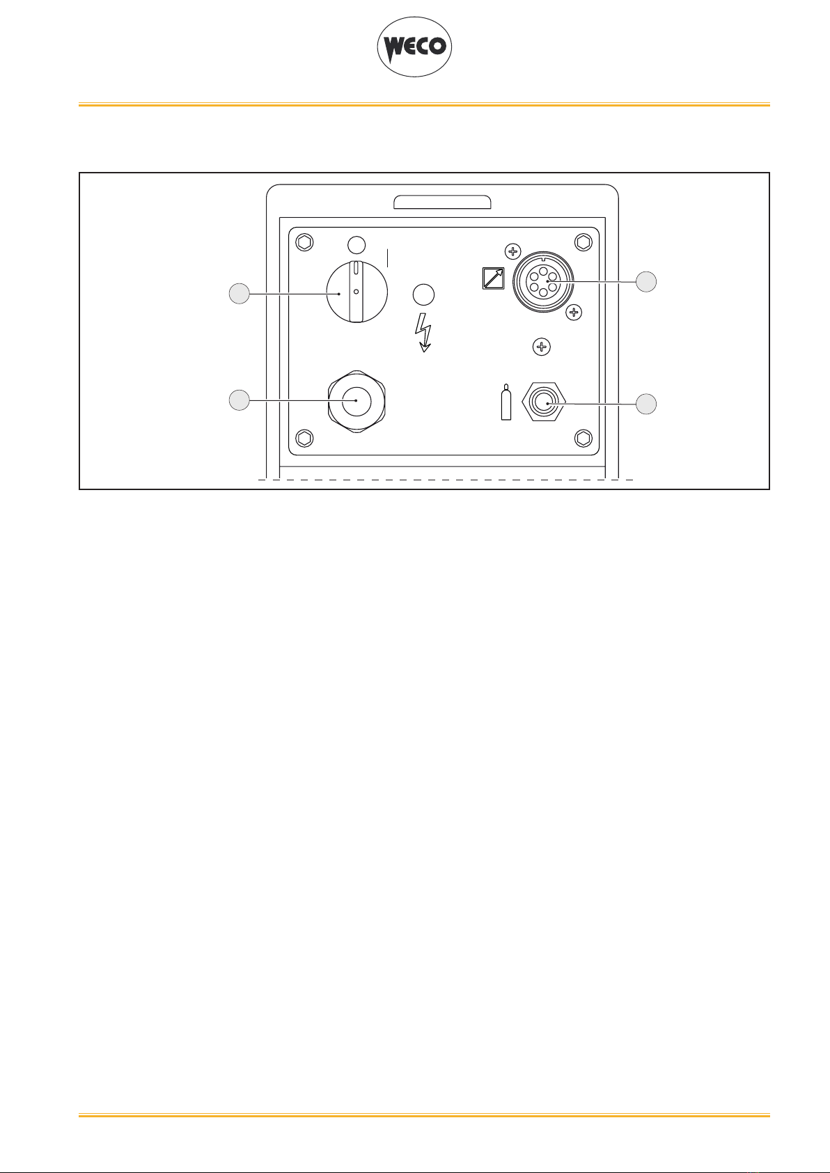
2.3 REAR PANEL............................................................................................................................................... 7
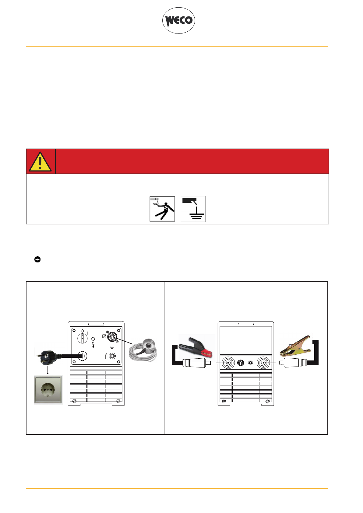
2.4 PREPARING FOR MMA WELDING............................................................................................................. 8
2.5 PREPARING FOR TIG WELDING ............................................................................................................... 9
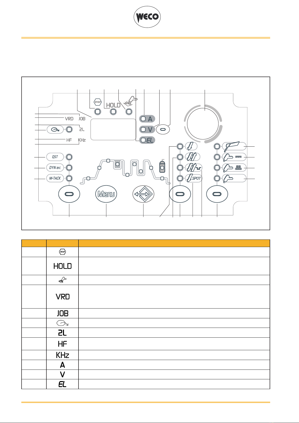
3 USER INTERFACE .................................................................................................................................... 10
4 UNIT POWER-UP ...................................................................................................................................... 12
5 RESET (LOAD FACTORY SETTINGS)..................................................................................................... 13
6 SET-UP (INITIAL SET-UP OF THE WELDING POWER SOURCE) ......................................................... 14
7 ALARM MANAGEMENT ........................................................................................................................... 16
8 MMA WELDING......................................................................................................................................... 17
8.1 MMA WELDING - FIRST LEVEL MENU .................................................................................................... 17
8.2 MMA WELDING - SECOND LEVEL MENU ............................................................................................... 19
8.3 MMA WELDING - SPECIAL FUNCTIONS ................................................................................................. 21
9 DC TIG WELDING ..................................................................................................................................... 22
9.1 DC TIG WELDING - FIRST LEVEL MENU ................................................................................................ 22
9.2 TIG DC WELDING - SECOND LEVEL MENU ........................................................................................... 27
9.3 TIG DC WELDING - SPECIAL FUNCTIONS MENU ................................................................................. 30
10 TORCH TRIGGER PROCEDURE ............................................................................................................. 34
10.1 2 STROKE SPOT - Q-SPOT FUNCTION .................................................................................................. 40
11 JOBS MANAGEMENT .............................................................................................................................. 45
11.1 SAVING A JOB ........................................................................................................................................... 45
11.2 DELETING A JOB ...................................................................................................................................... 46
11.3 LOADING A JOB ........................................................................................................................................ 47
11.4 SELECTING JOBS USING THE TORCH BUTTONS ................................................................................ 47
12 TECHNICAL DATA .................................................................................................................................... 48
12.1 DISCOVERY 172T ..................................................................................................................................... 48
13 WIRING DIAGRAM.................................................................................................................................... 50
13.1 TORCH CONNECTOR (front panel) .......................................................................................................... 51
13.2 REMOTE CONTROL CONNECTOR (back panel)..................................................................................... 51
14 SPARES..................................................................................................................................................... 52
14.1 DISCOVERY 172T ..................................................................................................................................... 52
14.2 TORCH CONNECTORS COMPLETE KIT................................................................................................. 54

WELD THE WORLD
Cod. 006.0001.1960
03/05/2019 V.2.2 Discovery 172T
4
ENGLISH
1 INTRODUCTION
IMPORTANT!
This handbook must be consigned to the user prior to installation and commissioning of the unit.
Read the "General prescriptions for use" handbook supplied separately from this handbook before
installing and commissioning the unit.
The meaning of the symbols in this manual and the associated precautionary information are given in
the "General prescriptions for use”.
If the "General prescriptions for use" are not present, it is mandatory to request a replacement copy
from the manufacturer or from your dealer.
Retain these documents for future consultation.
LEGEND
DANGER!
This pictogram warns of danger of death or serious injury.
WARNING!
This pictogram warns of a risk of injury or damage to property.
CAUTION!
This pictogram warns of a potentially hazardous situation.
INFORMATION!
This pictogram gives important information concerning the execution of the relevant operations.
This symbol identies an action that occurs automatically as a result of a previous action.
This symbol identies additional information or a reference to a different section of the manual
containing the associated information.
§ This symbol identies a reference to a chapter of the manual.
*1 The symbol refers to the associated numbered note.
NOTES
The gures in this manual are purely guideline and the images may contain differences with respect to
the actual equipment to which they refer.

WELD THE WORLD
Cod. 006.0001.1960
03/05/2019 V.2.2
Discovery 172T
5
ENGLISH
1.1 PRESENTATION
Discovery 172T is an inverter DC TIG/MMA portable welding power source.
The sturdiness of the components of this unit makes it a reliable working companion for workshop and
outdoor applications.
The available DC TIG functions and digital control make this unit ideal for maintenance, building con-
struction, and light metalwork.
In MMA welding the Hot Start and Arc Force functions are adjustable and they allow improved arc strik-
ing, a atter bead and more uniform weld.
The Anti Sticking function makes it possible to detach the electrode rapidly from the workpiece in the
event of accidental sticking.
Up to 4,00mm diameter electrode welding is possible in MMA.
The welding modes and procedures available are those indicated in the table.
MODE PROCEDURE
MMA
TIG CONTINUOUS
2 STROKE LIFT-ARC (2T)
+ 2 STROKE + HF (2T HF)
4 STROKE LIFT-ARC (4T)
TIG PULSED
+ 4 STROKE + HF (4T HF)
4 STROKE BI-LEVEL (4T B-LEVEL)
+ 4 STROKE BI-LEVEL + HF (4T B-LEVEL HF)
SYNERGIC TIG
2T SPOT
+ 2T SPOT + HF
Accessories that can be connected to the unit:
• manual remote control for remote adjustment of the welding current.
• foot-pedal remote control for TIG torch arc striking and remote adjustment of welding current.
• UP/DOWN torch or torch with potentiometer.

WELD THE WORLD
Cod. 006.0001.1960
03/05/2019 V.2.2 Discovery 172T
6
ENGLISH
2 INSTALLATION
DANGER!
Lifting and positioning
Read the warnings highlighted by the following symbols in the “General prescriptions for use”.
2.1 CONNECTIONS TO THE MAINS POWER SUPPLY
The characteristics of the mains power supply to which the equipment shall be connected are given in
the chapter entitled “12 TECHNICAL DATA” on page 48.
The machine can be connected to motor-generators provided their voltage is stabilised.
Connect/disconnect the various devices with the machine switched off.
2.2 FRONT PANEL
31 4 2
○ Positive pole welding socket.[Item 1].
○ Negative pole welding socket.[Item 2].
○ Connector for logic signals of TIG torch.[Item 3].
○ Connector for gas feed hose: Torch power source [Item 4].

WELD THE WORLD
Cod. 006.0001.1960
03/05/2019 V.2.2
Discovery 172T
7
ENGLISH
2.3 REAR PANEL
1
4
2
3
○ Welding power source ON/OFF switch [Item 1].
○ Remote control connector [Item 2].
○ Connector for gas feed hose [Item 3]
• cylinder-generator
○ Power cable. [Item 4].
• Total length (including internal part): 2.5 m;
• Number and cross section of wires: 3 x 2.5 mm2
• Type of plug supplied: Schuko

WELD THE WORLD
Cod. 006.0001.1960
03/05/2019 V.2.2 Discovery 172T
8
ENGLISH
2.4 PREPARING FOR MMA WELDING
1. Set the welding power source ON/OFF switch to “O” (unit off).
2. Plug the power cable plug into a mains socket.
3. Choose the electrode based on the type of material and thickness of the workpiece to be welded.
4. Insert the electrode in the electrode holder.
5. Connect the electrode holder clamp plug to the following welding socket: Positive pole welding
socket.
6. Connect the earth clamp plug to the following welding socket: Negative pole welding socket.
7. Connect the earth clamp to the workpiece being processed.
DANGER!
Electric shock hazard!
Read the warnings highlighted by the following symbols in the “General prescriptions for use”.
8. Set the welding power source ON/OFF switch to “I” (unit on).
9. Select the following welding mode on the user interface: MMA
10. Set the required welding parameter values on the user interface.
When the remote control [RC] is connected and enabled, the welding current can be adjusted.
The system is ready to start welding.
REAR VIEW FRONT VIEW

WELD THE WORLD
Cod. 006.0001.1960
03/05/2019 V.2.2
Discovery 172T
9
ENGLISH
2.5 PREPARING FOR TIG WELDING
1. Set the welding power source ON/OFF switch to “O” (unit de-energized).
2. Plug the power cable plug into a mains socket outlet.
3. Connect the gas hose from the welding gas cylinder to the rear gas connection.
4. Open the cylinder gas valve.
5. Connect the gas hose of the welding torch to the front gas connection.
6. Connect the electrode holder clamp plug to the following welding socket: Negative pole welding
socket.
7. Choose the electrode based on the type of material and thickness of the workpiece to be welded.
8. Insert the electrode in the TIG torch.
9. Connect the earth clamp plug to the following welding socket: Positive pole welding socket.
10. Connect the earth clamp to the workpiece being processed.
11. Set the welding power source ON/OFF switch to “I” (unit powered).
12. Select the following welding mode on the user interface: DC TIG
13. Press the torch trigger with the torch well clear of any metal parts. This serves to open the gas
solenoid valve without striking the welding arc.
14. Use the ow control valve to adjust the ow of gas as required while the gas is owing out.
15. Set the required welding parameter values on the user interface.
When the remote control pedal is connected and the relative locking screw is tightened the
welding current will vary in relation to the pressure exerted on the pedal.
The system is ready to start welding.
REAR VIEW FRONT VIEW

WELD THE WORLD
Cod. 006.0001.1960
03/05/2019 V.2.2 Discovery 172T
10
ENGLISH
3 USER INTERFACE
Discovery 172T
SYN
L1 L2 L3
L15
L13
L14
L10 L11L12
L29 L28
D1 S1
S2
E1
L6
S3 S4 S5 S6
L9
L8
L4
L5
L7
L33
L31
L32
L30
L26 L27
L18
L22
L20
L21
L23
L24
L25
L17
L16
L19
CODE SYMBOL DESCRIPTION
L1 This LED illuminates to show an anomaly in the operating conditions.
L2
Illuminates to show the last voltage and current values measured during welding.
The value appears on the display D1:
The “HOLD” function is cleared when a new weld is started or when any setting is changed.
L3 This LED illuminates to conrm the presence of power on the output sockets.
L4
Illumination shows that the following function has been activated: VRD (reduced output volt-
age).
The no-load voltage between the welding sockets is switched from U0 to Ur (see technical
data).
L5 Illuminates to show that a previously saved JOB has been loaded.
L6 This LED indicates that the current reference is set up by the remote control.
L7 When this LED illuminates the 2nd level Menu parameter is shown.
L8 Illumination shows that the following function has been activated: HIGH FREQUENCY ARC
STRIKE (HF)
L9 Illuminates to show a value in the following unit of measurement: KILOHERTZ
L10 Illuminates to show a value in the following unit of measurement: AMPERES
L11 Illuminates to show a value in the following unit of measurement: VOLTS
L12 Illumination shows that the following parameter can be displayed: ELECTRODE TYPE

WELD THE WORLD
Cod. 006.0001.1960
03/05/2019 V.2.2
Discovery 172T
11
ENGLISH
L13 Illumination shows that the following parameter can be set: Q-START
L14 Illumination shows that the following parameter can be set: DYNAMIC ARC
L15 Illumination shows that the following parameter can be displayed: MULTI TACK
L16 Illumination shows that the following parameter can be set: STARTING CURRENT (%/A)
L17 Illumination shows that the following parameter can be set: SLOPE UP (s)
L18 Illumination shows that the following parameter can be set: WELDING CURRENT (A)
L19 Illumination shows that the following parameter can be set: SECOND CURRENT B-LEVEL (%)
L20 Illumination shows that the following parameter can be set: BASE CURRENT (A)
L21 Illumination shows that the following parameter can be set: PEAK TIME (s)
L22 illumination shows that the following parameter can be set: BASE TIME(s)
L21 + L22 illumination shows that the following parameter can be set: PULSED CURRENT FREQUENCY
(Hz/kHz)
L23 illumination shows that the following parameter can be set: SLOPE DOWN (s)
L24 illumination shows that the following parameter can be set: STARTING CURRENT (%/A)
L25 illumination shows that the following parameter can be set: POST-GAS (s)
L26 Illumination shows that the following function has been activated: 2 stroke procedure.
L27 Illumination shows that the following function has been activated: 4 stroke procedure.
L28 Illumination shows that the following function has been activated: 4 stroke Bi-level procedure
L29 Illumination shows that the following function has been activated: 2 stroke spot procedure
(SPOT).
L30 This LED illuminates to show that the following welding mode is selected: MMA
L31 This LED illuminates to show that the following welding mode is selected: TIG DC CONTINU-
OUS
L32 This LED illuminates to show that the following welding mode is selected: PULSED DC TIG
L33
This LED illuminates to show that the following welding mode is selected: SYNERGIC PULSED
TIG
When this is on, it means that the synergic mode is active and that the operator can set just the
welding current while the other parameters are automatically regulated by the machine. The
synergy is optimised by angle welding.

WELD THE WORLD
Cod. 006.0001.1960
03/05/2019 V.2.2 Discovery 172T
12
ENGLISH
D1
Data setting: The display shows the acronym of the parameter to be set.
Welding: The display shows the effective amperes value during welding.
HOLD function: The display shows the average current value measured over the entire welding
period (excluding the starting and ending slopes).
E1 Data setting: The encoder sets the value of the selected parameter.
Welding: The encoder sets the value of the following parameter: WELDING CURRENT
S1
Parameters/functions setting: This button selects the parameter to be shown on the following
display: D1
Possible choices:
(A) Preset welding current
(V) No-load voltage
(EL) Preset type of electrode
Welding: This button selects the parameter to be shown on the following display: D1
Possible choices:
(A) Effective welding current
(V) Effective welding voltage
HOLD function: This button selects the parameter to be shown on the following display: D1
Possible choices:
(A) Average welding current
(V) Average welding voltage
S2
TIG Mode: Press the button to select the parameter to be set.
Possible selections: Q-START, DYNAMIC ARC, MULTI TACK
MMA mode: DYNAMIC ARC
S3
Press and release: the button selects the rst level menu parameters.
Hold down for 3 seconds: the button opens the second level menu. When in the menu, press
and release the button to select the parameters.
Keep the button pressed while powering on the power source: the button opens the SETUP
menu.
S4 Press and release: the button opens the JOBs upload menu.
Hold down for 3 seconds: the button opens the JOBs save and delete menu.
S5 TIG DC / TIG AC mode: This button selects the torch trigger procedure.
MMA mode: Press the button to show the selected electrode type for MMA welding.
S6 This button selects the welding mode.
4 UNIT POWER-UP
Set the welding power source ON/OFF switch to “I” to switch on the unit.
FX.X The message appears on the following display: D1.
x.x= software version
First power-up or power-ups following a RESET procedure
The welding power source sets up for welding with the factory preset values.
Subsequent power-ups
The welding power source sets up for welding in the latest stable welding conguration that was active
at the time of power-off.

WELD THE WORLD
Cod. 006.0001.1960
03/05/2019 V.2.2
Discovery 172T
13
ENGLISH
5 RESET (LOAD FACTORY SETTINGS)
SYN
L1 L2 L3
L15
L13
L14
L10 L11L12
L29 L28
D1 S1
S2
E1
L6
S3 S4 S5 S6
L9
L8
L4
L5
L7
L33
L31
L32
L30
L26 L27
L18
L22
L20
L21
L23
L24
L25
L17
L16
L19
FAC
AA
ACTIVATION ACTIVATION
The reset procedure involves complete restoration of the default values, parameters and memory set-
tings set in the factory.
All memory locations will be reset and hence all your personal welding settings will be lost!
The reset procedure is useful in the following cases:
- Too many changes made to the welding parameters so user nds it difcult to restore defaults.
- Unidentied software problems that prevent the welding power source from functioning correctly.
A
○ Set the welding power source ON/OFF switch to “O” to switch the unit off.
○Keeping both the S2 and S6 buttons pressed, set the generator power source
switch to “I” to turn on the equipment [ SIMULTANEOUS ACTIONS]
○ Press both buttons S2 and S6
FAC: The message will appear on display D1
- Wait for the memory clear procedure to terminate. This action will automatically close the
menu.

WELD THE WORLD
Cod. 006.0001.1960
03/05/2019 V.2.2 Discovery 172T
14
ENGLISH
6 SET-UP (INITIAL SET-UP OF THE WELDING POWER SOURCE)
SYN
L1 L2 L3
L15
L13
L14
L10 L11L12
L29 L28
D1 S1
S2
E1
L6
S3 S4 S5 S6
L9
L8
L4
L5
L7
L33
L31
L32
L30
L26 L27
L18
L22
L20
L21
L23
L24
L25
L17
L16
L19
SEt
AC
ACTIVATION/
SELECTION EXIT
B
SETTING
A
○ Set the welding power source ON/OFF switch to “O” to switch the unit off.
○Holding the S3 button down, turn the power source switch to “I” to start the equipment. [
SIMULTANEAOUS ACTIONS]
Set : The message will appear for a few seconds on display D1.
○Press the S3 button to conrm.
The value relative to the selected setting will appear on display D1.
B○Using the encoder E1 , edit the value of the selected setting.
C
○Exit with conrmation
- Press any button (except S3) for example S4 to save the setting and quit the
menu.
Tab. 1 - Setup settings
ACRONYM / LED SETTING MIN DEFAULT MAX
St.C. STARTING CURRENT %%A
F.Cu. FINAL CURRENT %%A
HF.C. HF CURRENT 20 A SYn 150 A
PUL. TYPE OF PULSED CURRENT SLo. FA. FA.
P.A. PILOT ARC oFF on on
StS SPECIAL TORCH STROKE oFF oFF 2
rHF RESTART HF oFF on on

WELD THE WORLD
Cod. 006.0001.1960
03/05/2019 V.2.2
Discovery 172T
15
ENGLISH
- St.C. [STARTING CURRENT]
○ The value of this parameter can be set as a percentage of the welding current or as an absolute
value expressed in Amperes.
F.Cu. [FINAL CURRENT]
○ The value of this parameter can be set as a percentage of the welding current or as an absolute
value expressed in Amperes.
- HF.C. [HF CURRENT]
○ This parameter establishes the current value during HF discharge. The value of this parameter
can be set as an absolute value or in SYN.
○ With SYN setting the HF current value is calculated automatically on the basis of the preset weld-
ing current value.
Consequences of a higher value:
• Arc striking is facilitated, even on very dirty workpieces.
• Risk of piercing excessively thin gauge workpieces.
- PUL. [TYPE OF PULSED CURRENT]
○ SLo. = This setting enables slow pulsed mode. The peak time and Base time are set.
○ FA.= This setting enables fast pulsed mode. The frequency and duty-cycle are set.
- P.A. [PILOT ARC]
○ The function enables the output of a low current between the 1st and 2nd times of the torch trig-
ger to shield the mask in advance and avoid the risk of blinding ashback caused by the welding
current.
-StS [SPECIAL TORCH STROKE]
○The parameter changes the torch trigger operating mode.
○ oFF: indicates standard operation.
○ 1: species the 4T B-level management variant. Allows the transition to the secondary welding
current by pressing and holding down the UP or DOWN button; when the button is released, the
primary current is restored. With variant oFF selected, the UP/DOWN buttons are disabled for all
procedures.
○ 2: species the down slope management variant. By releasing the torch trigger during the third
stroke (3S) the down slope is stopped and the nal current is immediately delivered without ha-
ving to go through the entire slope time.
-rHF [RESTART HF]
○ This parameter changes the HF arc striking operation in the HF 4 stroke torch button mode. When
set to “oFF”, the automatic HF arc striking discharge is disabled when the long arc welding mode is
exited; to restart the welding operation, the torch trigger must be pressed again. When set to “on”
and the long arc welding mode is exited, the HF discharge is automatically started as soon as the
torch electrode approaches the workpiece. Disabling the automatic striking is useful to prevent the
accidental arc striking when the torch touches a part connected to the equipment earth (such as the
welding table) after exiting the long arc welding mode.

WELD THE WORLD
Cod. 006.0001.1960
03/05/2019 V.2.2 Discovery 172T
16
ENGLISH
7 ALARM MANAGEMENT
This LED illuminates if an incorrect operating condition occurs.
An alarm message will appear on display D1.
Tab. 2 - Alarm messages
MESSAGE MEANING EVENT CHECKS
Al. H.
Overheating alarm
Indicates tripping of the welding
power source thermal protection.
Leave the unit running so that the
overheated components cool as
rapidly as possible.
When the unit has cooled, the
welding power source will reset
automatically.
All functions disabled.
Exceptions:
• Cooling fan.
• Make sure that the power re-
quired by the welding process is
lower than the maximum rated
power output.
• Check that the operating con-
ditions are in compliance with
the welding power source data
plate specications.
• Check for the presence of ade-
quate air circulation around the
welding power source.
E. 04 Alarm, no-load voltage failure
All functions disabled.
Exceptions:
• Cooling fan
• Check to ensure the welding
torch is not resting on the work-
piece connected to ground.
• Check that when the power
source is switched on there
is no short circuit between the
sockets (voltage must be great-
er than/equivalent to Ur).
If the problem persists:
• qualied technical personnel
are required for repair/mainte-
nance jobs.

WELD THE WORLD
Cod. 006.0001.1960
03/05/2019 V.2.2
Discovery 172T
17
ENGLISH
8 MMA WELDING
8.1 MMA WELDING - FIRST LEVEL MENU
SYN
L1 L2 L3
L15
L13
L14
L10 L11L12
L29 L28
D1 S1
S2
E1
L6
S3 S4 S5 S6
L9
L8
L4
L5
L7
L33
L31
L32
L30
L26 L27
L18
L22
L20
L21
L23
L24
L25
L17
L16
L19
80
B A ACTIVATION
SELECTION
C
SETTING
A
○Press the S6 button to activate the MMA mode.
A
SYN
S6
L33
L31
L32
L30
L30 MMA
B
○Press the S3 button.
○Use the encoder E1 to scroll the list of settings to be edited.
The acronym relative to the selected setting is shown on display D1.
○Press the S3 button to conrm.
The value relative to the selected setting appears on display D1.
C○Using the encoder E1 to edit the value of the selected setting.

WELD THE WORLD
Cod. 006.0001.1960
03/05/2019 V.2.2 Discovery 172T
18
ENGLISH
Tab. 3 - Parameters of 1st level menu: mode
ACRONYM / LED SETTING MIN DEFAULT MAX NOTES
L18 WELDING CURRENT
MAXIMUM CURRENT WITH REMOTE CONTROL 10 A 80 A 180 A
Ho.S. HOT-START 0 % SYn 100 % *1 - *2
Ar.F. ARC FORCE 0 % SYn 250 % *1 - *2
*1: This parameter is set as a percentage referred to the value of the following parameter: WELDING
CURRENT
*2: SYN: This code indicates that parameters control is synergic. The optimal value of this parameter
is set automatically by the microprocessor on the basis of the preset welding current value. This
value can be displayed but it is not user-adjustable.
When SYN is installed, to display the synergic value press the following button: S1
Press any button (except S3) to save the setting and exit the menu.
- WELDING CURRENT
○ This parameter regulates the primary welding current value.
- MAXIMUM CURRENT WITH REMOTE CONTROL
○ The maximum output current value that can be achieved with foot pedal control external refer-
ence.
- HOT-START
○This parameter aids electrode melting at the time of arc striking. It is set as a percentage re-
ferred to the value of the following parameter: WELDING CURRENT. The value is limited
to maximum 250A.
- Consequences of a higher value:
• Ease of activation; Greater starting spatter; increase in the activation area.
- Consequences of a lower value:
• Difculty of activation; Less starting splatter; Reduction in the activation area.
- ARC-FORCE
○ This parameter helps to avoid electrode sticking during welding. It is set as a percentage referred
to the value of the following parameter: WELDING CURRENT
- Consequences of a higher value:
• Fluency factors in welding; Arc welding stability;Increased melting of the electrode within the
workpiece; More weld spatter.
- Consequences of a lower value:
• The arc is extinguished more easily, less welding spatter.

WELD THE WORLD
Cod. 006.0001.1960
03/05/2019 V.2.2
Discovery 172T
19
ENGLISH
8.2 MMA WELDING - SECOND LEVEL MENU
SYN
L1 L2 L3
L15
L13
L14
L10 L11L12
L29 L28
D1 S1
S2
E1
L6
S3 S4 S5 S6
L9
L8
L4
L5
L7
L33
L31
L32
L30
L26 L27
L18
L22
L20
L21
L23
L24
L25
L17
L16
L19
EL.
A3 sec ACTIVA-
TION/SELECTION
B
SETTING
A
○ Hold down the S2 button for 3 seconds to access the 2nd level menu.
The LED will illuminate.
○Use the encoder E1 to scroll the list of settings to be edited.
The acronym relative to the selected setting is shown on display D1.
○Press the S3 button to conrm.
The value relative to the selected setting appears on display D1.
B○Using the encoder E1 , edit the value of the selected setting.
Tab. 4 - Parameters of the 2nd level menu: MMA mode
ACRONYM / LED SETTING MIN DEFAULT MAX NOTES
EL. ELECTRODE TYPE - bAS -
bAS= basic
rUt= rutile
Crn= chromium/
nickel
ALU= aluminium
Urd VRD (OUTPUT VOLTAGE REDUCTION) oFF oFF On *4
U.EL. LONG ARC VOLTAGE MMA 37 SYn 65 *2
rC REMOTE CONTROL ACTIVATION oFF oFF On *3
Press any key (except S3) to save the setting and quit the menu.
*2: SYN: This code indicates that parameters control is synergic. The optimal value of this param-
eter is set automatically by the microprocessor on the basis of the preset welding current value.
This value can be displayed but it is not user-adjustable.
When SYN is installed, to display the synergic value press the following button: S1

WELD THE WORLD
Cod. 006.0001.1960
03/05/2019 V.2.2 Discovery 172T
20
ENGLISH
*3: The activation is suitable for the following welding modes:
• MMA
• DC TIG
Compatible remote control types:
• manual remote control.
*4: The activation is suitable for the following welding modes:
• MMA
- ELECTRODE TYPE
○ This parameter allows for the selection of the type of electrode to be used. The selection auto-
matically allows the optimum welding parameters to be set.
- VRD
○ This parameter reduces the potential across the welding sockets when welding is not in progress.
- The arc strike procedure is as follows:
• Touch the workpiece with the electrode tip.
• Raise the electrode.
• Power is released for several seconds.
• Touch the workpiece with the electrode tip.
• The welding arc will strike.
- LONG ARC VOLTAGE
○ This parameter inhibits power output when the potential between electrode and workpiece ex-
ceeds the preset threshold level.
- Consequences of a higher value:
• The welding arc persists even with a signicant distance between the electrode and the work-
piece.
- Consequences of a lower value:
• Faster exit from weld.
Table of contents
Other Weco Inverter manuals

Weco
Weco Cruiser 402 T User manual

Weco
Weco Multi Power 204T User manual

Weco
Weco Pioneer Pulse 321MKS User manual

Weco
Weco Discovery 150TP-VRD User manual

Weco
Weco Multi Power 184 User manual

Weco
Weco Pioneer 403MSR User manual

Weco
Weco ESS XTE Series User manual

Weco
Weco Discovery 162T User manual

Weco
Weco Pioneer Pulse 321MKS User manual