Cod. 006.0001.1600
11/07/2022 V.2.12
Pioneer 321 MKS
3
ENGLISH
INDEX
1 INTRODUCTION.......................................................................................................................................... 5
1.1 INTRODUCTION.......................................................................................................................................... 6
2 INSTALLATION ........................................................................................................................................... 6
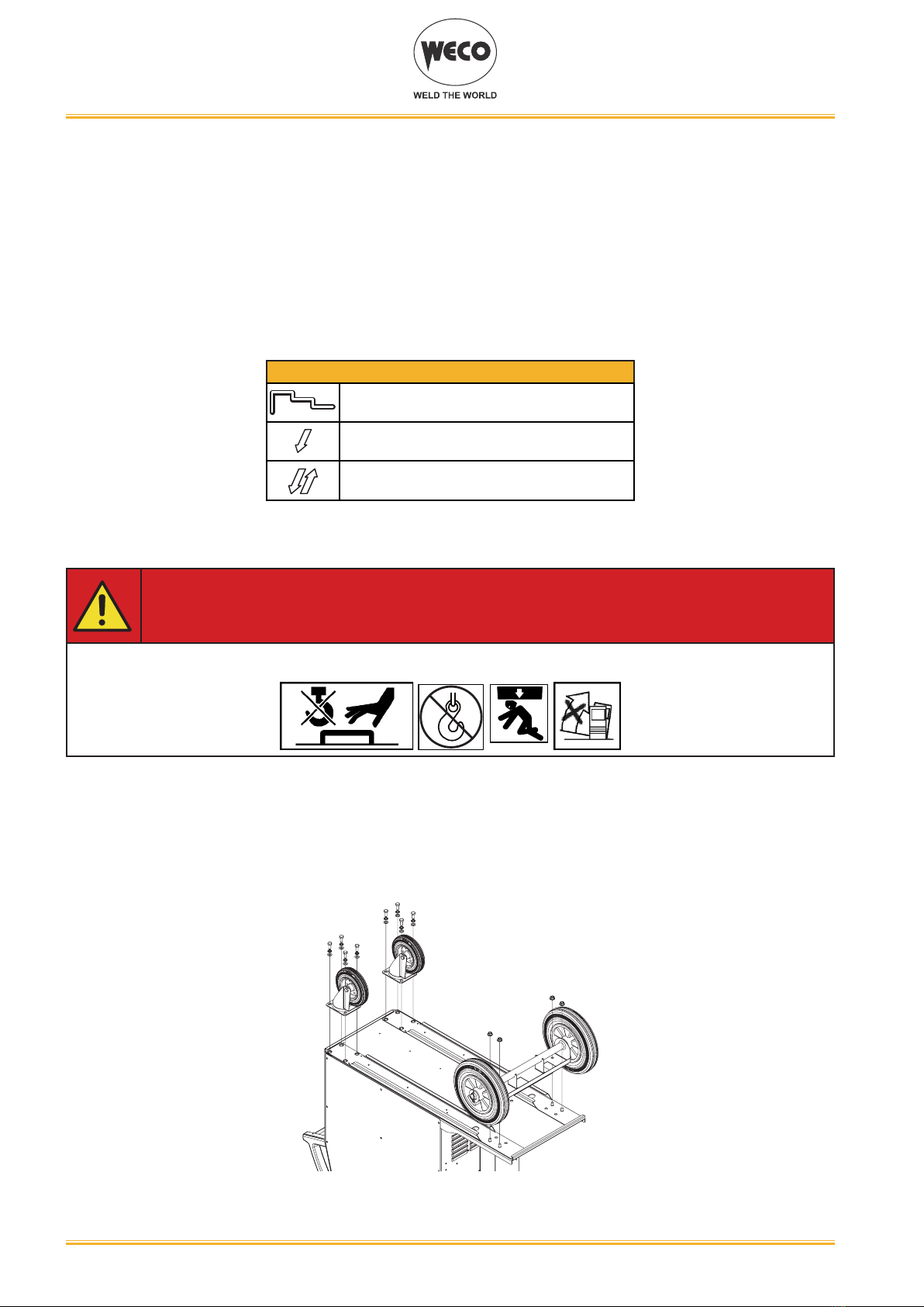
2.1 UNIT ASSEMBLY ......................................................................................................................................... 6
2.2 CONNECTIONS TO THE MAINS POWER SUPPLY................................................................................... 7
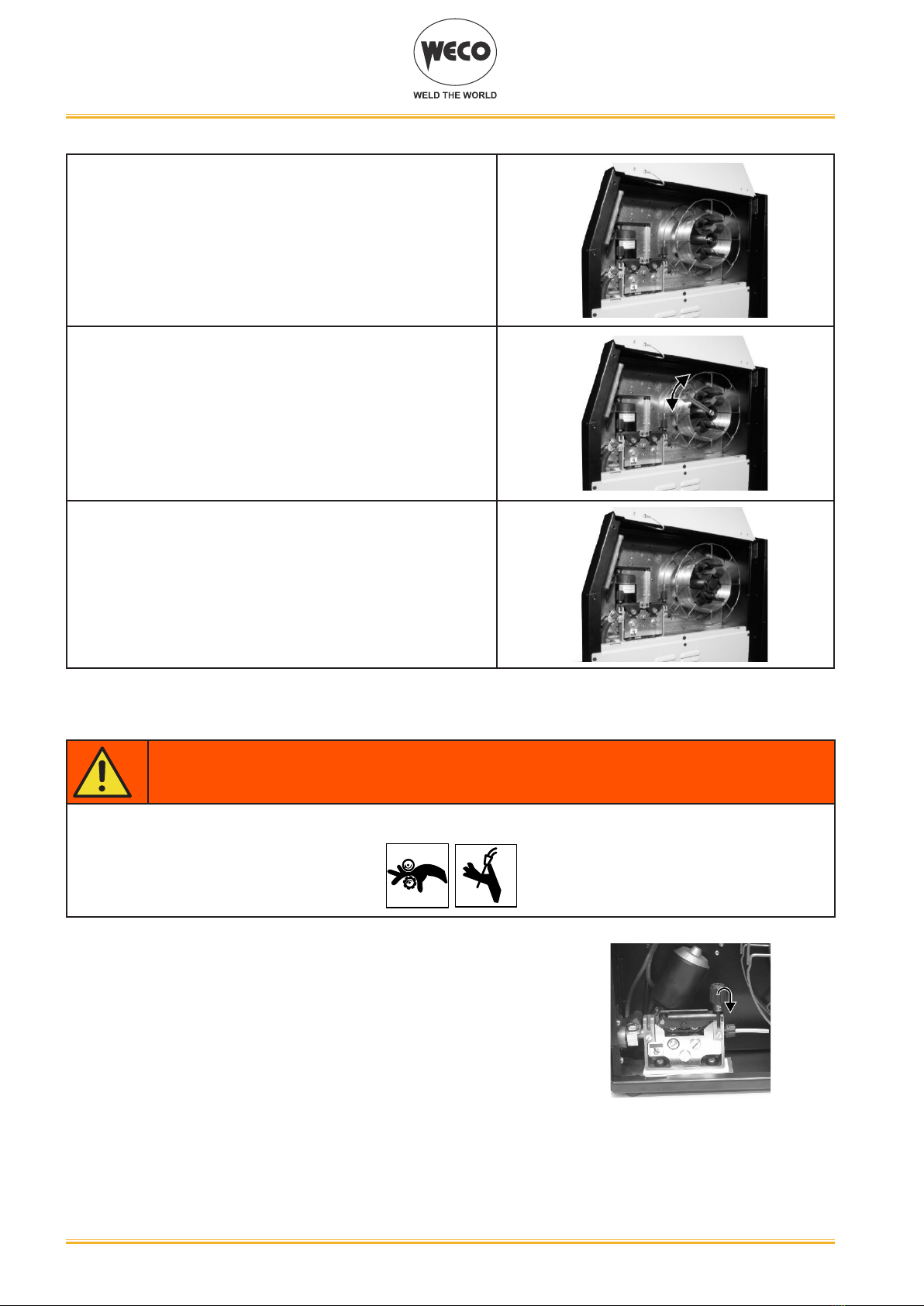
2.3 WIRE SPOOL POSITIONING ...................................................................................................................... 7
2.4 POSITIONING THE WIRE IN THE WIRE FEEDER .................................................................................... 8
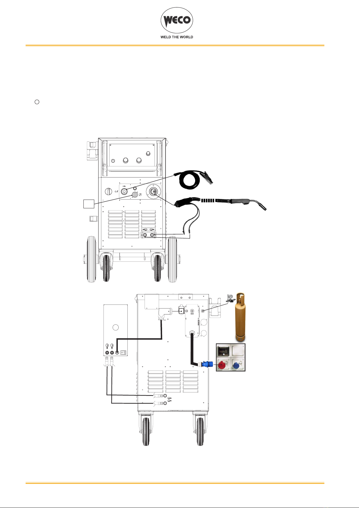
2.5 CONNECTIONS TO SOCKETS................................................................................................................... 9
2.6 FRONT PANEL........................................................................................................................................... 11
2.7 REAR PANEL............................................................................................................................................. 12
3 COMMISSIONING ..................................................................................................................................... 14
3.1 USER INTERFACE .................................................................................................................................... 14
3.2 UNIT POWER-UP ...................................................................................................................................... 17
3.3 RESET (LOAD FACTORY SETTINGS) ..................................................................................................... 17
3.3.1 PARTIAL RESET..................................................................................................................................... 17
3.3.2 TOTAL RESET ........................................................................................................................................ 18
3.4 SET-UP (INITIAL SET-UP OF THE WELDING POWER SOURCE) .......................................................... 18
3.5 LOCKING PROCEDURE ........................................................................................................................... 20
3.6 GAS FLOW ADJUSTMENT ....................................................................................................................... 21
3.7 TORCH LOADING ..................................................................................................................................... 21
4 ALARM MANAGEMENT ........................................................................................................................... 22
5 WELDING SETTINGS ............................................................................................................................... 23
5.1 TORCH TRIGGER MODES ....................................................................................................................... 23
5.1.1 2 STROKE MIG/MAG WELDING (2T) .................................................................................................... 23
5.1.2 4 STROKE MIG/MAG WELDING (4T) .................................................................................................... 23
5.1.3 3 LEVEL MIG/MAG WELDING ............................................................................................................... 23
5.2 PARAMETERS ACTIVATION ..................................................................................................................... 24
5.3 WELDING PARAMETERS ......................................................................................................................... 24
6 WELDING SETTINGS ............................................................................................................................... 26
6.3.1 PARAMETERS SETTING ....................................................................................................................... 26
6.3.2 PARAMETERS SETTING: (1ST LEVEL)................................................................................................ 27
6.3.3 PARAMETERS SETTING: (2ND LEVEL) ............................................................................................... 28
6.3.4 PARAMETERS SETTING: (GAS MENU)................................................................................................ 28
6.1 JOBS MANAGEMENT ............................................................................................................................... 28
6.2 SAVING A JOB ........................................................................................................................................... 29
6.3 LOADING A USER JOB ............................................................................................................................. 29
6.4 DELETING A JOB ...................................................................................................................................... 29
7 TECHNICAL DATA .................................................................................................................................... 30
8 WIRING DIAGRAM.................................................................................................................................... 32
8.1 REMOTE CONTROL CONNECTOR (front panel)..................................................................................... 37
8.1.1 RC03: Wiring diagram............................................................................................................................. 37
8.1.2 RC04: Wiring diagram............................................................................................................................. 37
8.1.3 RC05: Wiring diagram............................................................................................................................. 38
8.1.4 RC06: Wiring diagram............................................................................................................................. 38
8.2 PUSH-PULL (OPTIONAL).......................................................................................................................... 38