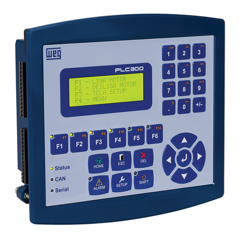
WEG PLC300 H3 User manual

Programmable Logic Controller
Controlador Lógico Programable
Controlador Lógico Programável
PLC300 H3
Instalation Guide
Guia de Instalación
Guia de Instalação
Motors | Automation | Energy | Transmission & Distribution | Coatings

Instalation Guide
Series: PLC300 H3
Language: English
Document: 10004755423 / 01
Models: with and without HMI
Publishing Date: 01/2019

Summary of Reviews
English
The information below describes the reviews made in this guide.
Version Review Description
-R00 First edition
-R01 General revision

Contents
English
1 SAFETY INSTRUCTIONS...................................................................4
1.1 SAFETY WARNINGS IN THIS GUIDE..................................................... 4
1.2 SAFETY WARNINGS IN THE PRODUCT ............................................... 4
1.3 PRELIMINARY RECOMMENDATIONS .................................................. 5
2 CONNECTORS....................................................................................6
2.1 CONNECTORS PINOUTS ....................................................................... 7
3 CONNECTIONS ..................................................................................9
3.1 DIGITAL INPUTS ..................................................................................... 9
3.2 DIGITAL OUTPUTS................................................................................. 10
3.3 ANALOG INPUT .......................................................................................11
3.4 ANALOG OUTPUT .................................................................................. 12
3.5 ENCODER INPUT................................................................................... 13
3.6 RS-232 INTERFACE ................................................................................14
3.7 RS-485 INTERFACE ............................................................................... 15
4 TECHNICAL SPECIFICATIONS ........................................................16

Safety Instructions
4 | PLC300
English
1 SAFETY INSTRUCTIONS
This quick installation guide contains the basic information necessary to commission
the PLC300. It has been written to be used by qualified personnel with suitable
training or technical qualification for operating this type of equipment. The personnel
shall follow all the safety instructions described in this manual defined by the local
regulations. Failure to comply with the safety instructions may result in death, serious
injury, and/or equipment damage.
For further information, refer to the user’s manual available for download on the
website: www.weg.net.
1.1 SAFETY WARNINGS IN THIS GUIDE
In this guide, the following safety warnings are used:
DANGER!
The procedures recommended in this warning have the purpose of
protecting the user against death, serious injuries and considerable
material damages.
ATTENTION!
The procedures recommended in this warning have the purpose of
avoiding material damages.
NOTE!
The information mentioned in this warning is important for the proper
understanding and good operation of the product.
1.2 SAFETY WARNINGS IN THE PRODUCT
The following symbols are attached to the product, serving as safety notices:
High voltages are present.
Components sensitive to electrostatic discharge.
Do not touch them.
Mandatory connection to the protective earth (PE).

Safety Instructions
PLC300 | 5
English
1.3 PRELIMINARY RECOMMENDATIONS
DANGER!
Only qualified personnel, familiar with PLC300 and related equipment
must plan or perform the installation, commissioning, operation and
maintenance of this equipment.
The personnel must follow the safety instructions described in this
guide and/or defined by local standards.
The noncompliance with the safety instructions may result in death
risk and/or equipment damage.
NOTE!
For the purposes of this guide, qualified personnel are those trained
in order to be able to:
1. Install, ground, power up and operate the PLC300 in accordance
with this guide and the safety legal procedures in force.
2. Use the protective equipment in accordance with the standards.
3. Give first aid.
DANGER!
Always disconnect the general power supply before touching any
electrical device associated to the PLC.
ATTENTION!
The electronic cards have component parts sensitive to electrostatic
discharge. Do not touch directly the component parts or connectors.
NOTE!
Fully read this guide before installing or operating this equipment.

Connectors
6 | PLC300
English
2 CONNECTORS
a)
XC3 S1 XC6
XC4
XC1
XC8
XC7 XC2
XC1 – digital and analog inputs.
XC2 – digital, PWM and analog outputs.
XC3 – encoder RS-232 and RS-485 input.
XC4 – Ethernet.
XC5 – USB.
XC6 – CAN.
XC7 – SD card.
XC8 – Power input 24 Vdc.
S1 – Turn on/off RS-485 termination resistors.
b)
Battery
Back
display
Back
key
XC11
Slot1
XC12
Slot2
XC5
XC11 – expansion slot 1
XC12 – expansion slot 2
Figure 2.1 (a) and (b) - Position of the connectors

Connectors
PLC300 | 7
English
2.1 CONNECTORS PINOUTS
For connectors XC1, XC2 and XC3 use AWG 30-16 cables.
XC1 – Digital and Analog Inputs
Table 2.1: Function of the digital and analog input pins
Pin Function
1DI1 - digital input 1.
2DI2 - digital input 2.
3DI3 - digital input 3.
4DI4 - digital input 4.
5DI5 - digital input 5.
6DI6 - digital input 6.
7DI7 - digital input 7.
8DI8 - digital input 8.
9 DI9 - digital input 9 (fast) (*).
10 DI10 - digital input 10 (*).
11 Common of the inputs DI1...DI8.
12 Common of the inputs DI9...DI10.
13 (AI1+) analog input 1 (+).
14 (AI1-) analog input 1 (-).
(*) DI9 and DI10 can be used for reading encoder signals, A and B,
respectively.
XC2 – Digital, PWM and Analog Outputs
Table 2.2: Function of the digital, PMW and analog output pins
Pin Function
1 DO1 - digital output 1.
2 DO2 - digital output 2.
3 DO3 - digital output 3.
4 DO4 - digital output 4.
5 DO5 - digital output 5.
6 DO6 - digital output 6.
7 DO7 - digital output 7.
8 DO8 - digital output 8.
9 DO9 - fast output 9 (PWM).
10 GNDBB – 0 V digital outputs.
11 VBB – (20...30 Vdc) for the digital outputs.
12 AO1(V) – analog output 1 in voltage.
13 AO1(I) – analog output 1 in current.
14 AO1 – common.

Connectors
8 | PLC300
English
XC3 – Encoder input, RS-232 and RS-485
Table 2.3: Function of the pins of the encoder, RS-232 and RS-485 input
Pino Função
1 A - encoder A signal.
2A - encoder A signal.
3 B - encoder B signal.
4B- encoder Bsignal.
5 Z - encoder Z signal.
6Z - encoder Z signal.
7 +5/12 Vdc - encoder supply.
8 0 V – encoder supply.
9RS-232 rate.
10 RS-232 RX.
11 RS-232 GND.
12 RS-485 signal A (-).
13 RS-485 signal B (+).
14 RS-485 GND (insulated).
XC6 – CAN
Table 2.4: Function of the pins of the XC6 - CAN
Pin Function
1 V -
2CANL
3SHIELD
4CANH
5 V + (11 to 30 Vdc)
XC8 – Power Supply
Table 2.5: Function of the pins of the XC8 - Power Supply
Pin Function
1 V+ (20 to 28 Vdc)
2GND
3 Ground
XC4 – Ethernet
Ethernet standard connector.

Digital Inputs
PLC300 | 9
English
3 CONNECTIONS
3.1 DIGITAL INPUTS
The 10 insulated digital inputs must be excited by an external source of 24 Vdc. The
inputs are bidirectional, which means the input common can be connected to either
the GND or the VDC of the supply.
The DIs 9 and 10 are faster and can read a signal of up to 100 kHz, and they can also
operate as encoder input. The other DIs can count up to 4 kHz.
24 Vcc
XC1
24 Vcc
PNP
XC1
PNP or NPN
DI
1
1 74 102 85 11 12 13 143 96 DI
9
DI
5
DI
3COM
1COM
2AI1
(+) AI1
(-)
DI
7
DI
2DI
10
DI
6
DI
4DI
8
(-)
(-)
(+)
(+)
Figure 3.1: Example of connection of the digital inputs (XC1)

Digital Inputs
10 | PLC300
English
3.2 DIGITAL OUTPUTS
The PLC300 has eight insulated and protected digital outputs, besides a fast PWM
output that can generate pulses of up to 300 kHz with variable duty cycle from 0 to
100 %.
This output can also be used as a standard digital output, but it is not protected.
The circuit of the digital outputs must be externally powered by a supply of 24 Vdc,
connected to the pins VBB(+) and GNDBB(-).
The outputs DO1 to DO8 are of PNP(1) type and can provide a current of up to 500
mA each.
DO9 is a Push-Pull(2) output, PWM type, and can supply up to 100 mA.
(1) PNP Output: activate load connected to GNDBB.
(2) Push-Pull Output: Bi-directional, i.e., activates the load connected to GNDBB or to VBB.
Supply
24 Vdc
XC2
L1 L2 L3
L4
DO
1
1 74 102 85 11 12 13 143 96
DO
9
DO
5
DO
3VBB COM
AO1
AO1
(I)
AO1
(V)
DO
7
DO
2GND
BB
DO
6
DO
4DO
8
(-)
(+)
Figure 3.2: Example of connection of the digital outputs (XC2)

Digital Inputs
PLC300 | 11
English
3.3 ANALOG INPUT
The analog input AI1 is differential, 12 bits, and can read signals from a voltage or
current source.
By means of the equipment setup, you can choose among the modes: voltage 0 to
10 V, current 0 to 20 mA or current 4 to 20 mA.
Below, a simple example of connection.
0 to 10 V
0 to 20 mA,
or
4 to 20 mA,
XC1
DI
1
1 74 102 85 11 12 13 143 96
DI
9
DI
5
DI
3COM
1COM
2AI1
(+) AI1
(-)
DI
7
DI
2DI
10
DI
6
DI
4DI
8
Figure 3.3: Example of connection of the analog input (XC1)

Digital Inputs
12 | PLC300
English
3.4 ANALOG OUTPUT
The analog output AO1, 10 bit resolution, has output in current and/or voltage, with
independent terminals.
In voltage, the output varies between 0 and 10 V. In current, the output range is from
0 to 20 mA, for a resistive load lower or equal to 500 Ω.
XC2
L2
I
L1
+
V
-
DO
1
1 74 102 85 11 12 13 143 96
DO
9
DO
5
DO
3VBB COM
AO1
AO1
(I)
AO1
(V)
DO
7
DO
2GND
BB
DO
6
DO
4DO
8
Figure 3.4: Example of connection of the analog output (XC2)

Digital Inputs
PLC300 | 13
English
3.5 ENCODER INPUT
The PLC300 features an insulated input for differential encoder, with its own supply
of 5 or 12 V. The maximum frequency of the pulses is 100 kHz. Maximum length of
the encoder cable: 30 m.
An internal insulated supply of 5 or 12 Vdc, with capacity of up to 300 mA, is available
for the encoder. The selection between 5 or 12 V must be done in the PLC setup.
The default value is 5 V.
(*) 5/12 V
A A B B Z Z 0 V
ENC
XC3
+V*
ENC
AENC
AENC
BENC
BENC
ZENC
ZENC
+V* ENC
0 V 232
TX 232
RX 232
GND 485
A485
B485
GND
1 74 102 85 11 12 13 14
396
Figure 3.5: Encoder connection
24 V Encoder : You can connect a 24 V encoder, since externally powered and only
signals A, B, and Z are used.
The 0 V of the encoder must be connected to 0 V of XC3 (pin 8)
A, B and Z signals are NOT tolerant to 24 V.
The signals A, B and Z can be used to fast counting and interrupts, also in 24 V.
Encoder PNP: if an encoder with PNP outputs is used, resistors of 1 K ohm must be
connected from the used signals to the 0 V.
E.g.: PNP encoder with A and B signals.

Digital Inputs
14 | PLC300
English
A
1KR 1KR
B0 V
(*) 5/12 V
ENC
XC3
+V*
ENC
AENC
AENC
BENC
BENC
ZENC
ZENC
+V* ENC
0 V 232
TX 232
RX 232
GND 485
A485
B485
GND
17
410
2 85 11 12 13 14
39
6
Figure 3.6: PNP encoder connection with signals A and B
3.6 RS-232 INTERFACE
This non-insulated RS-232 serial interface is intended to point-to-point communication.
Modem
RS232
RX
TX
GND
XC3
ENC
AENC
AENC
BENC
BENC
ZENC
ZENC
+V* ENC
0 V 232
TX 232
RX 232
GND 485
A485
B485
GND
17
4102 85 11 12 13 14
39
6
Figure 3.7: Connecting the RS-232

Digital Inputs
PLC300 | 15
English
ATTENTION!
Do not connect the GND of the RS232 (pin 11) to the ground of the
system.
Note: For further information, consult the manual for serial communication, available
for download on the website: www.weg.net.
3.7 RS-485 INTERFACE
Insulated, multipoint serial interface intended for network communication. It can
operate as master or slave with the Modbus RTU protocol.
The S1 key allows the connection of termination resistors.
Twisted pair
Bus RS-485
GND
A
B
XC3
ENC
AENC
AENC
BENC
BENC
ZENC
ZENC
+V* ENC
0 V 232
TX 232
RX 232
GND 485
A485
B485
GND
17
410
28
511 12 13 14
39
6
Figure 3.8: Connecting the RS-485
Note: For further information, consult the manual for serial communication, available
for download on the website: www.weg.net.

Technical Specifications
16 | PLC300
English
4 TECHNICAL SPECIFICATIONS
Supply:
Voltage: 24 Vdc ± 15 %.
Consumption of the PLC300 in 24 V: 250 mA.
Approximate consumption of each expansion: 30 mA.
Operating temperature
0 °C to 50 °C.
Degree of protection
IP65.
DI1 to DI10 Digital Inputs:
Bidirectional inputs.
Maximum input voltage 30 Vdc.
High level: Vin ≥ 10 V.
Low level: Vin ≤ 3 V.
Consumption in 24 V: 10 mA.
Maximum frequency DI1 to DI8: 4 kHz.
Maximum frequency DI9 and DI10: 100 kHz.
Insulation voltage: 500 V.
Delay time DI1 to DI8: 0→1: 20 µs; 1→0: 60 µs.
Delay time DI9 to DI10: 0→1: 8 µs; 1→0:32 µs.
DO1 to DO8 Digital Outputs:
PNP Outputs.
Maximum voltage in Vbb: 30 Vdc.
Maximum current of each output: 500 mA.
Delay time DO1 to DO8: 0→1: 40 us; 1→0: 125 us.
PWM DO9 Output:
Push-pull output.
Maximum voltage in Vbb: 30 Vdc.
Maximum current: 100 mA.
Maximum frequency: 300 kHz.
Note:
To use it as PWM, the maximum frequency must be 50 kHz so that the duty-cycle
is correct.
Analog Output
10-Bit Resolution.
Independent terminals for voltage and current.
Voltage output from 0 to 10 V.
Current output from 0 to 20 mA.
Maximum load 500 Ω for current output.

Technical Specifications
PLC300 | 17
English
Analog Input:
12- Bit Resolution.
Differential analog input.
Input impedance in voltage mode: 40 kΩ.
Input impedance in current mode: 500 Ω.
Encoder Input:
Maximum frequency: 100 kHz.
Encoder power supply: 5 or 12 Vdc.
Encoder maximum current: 300 mA.
Maximum length of the encoder cable: 30 m.
Update Time of Screens:
100 ms.
CAN interface:
Power Supply: 11 to 30 Vdc.
Maximum consumption in 24 V: 50 mA.
Memory:
SRAM Memory with battery, capacity of 1 MByte.
Up to 512 screens are programmed by the user.
Dynamic allocation of the area of application, markers, screens and alarms.
Scan Cycle for 1000 Program steps
For a simple program, done with 500 lines with contacts and coils, which resulted in
1000 instructions, the PLC300 presents the following characteristics:
Scan cycle, by KB of program: 133 µs/KB.
Occupied size: 12 KB.
Total scan cycle: 1.6 ms.


Guia de Instalación
Series: PLC300 H3
Idioma: Español
Documento: 10004755423 / 01
Modelos: con y sin HMI
Fecha de Publicación: 01/2019
Table of contents
Languages:
Other WEG Controllers manuals

WEG
WEG PLC500 Installation and operating instructions

WEG
WEG SSW06 User manual

WEG
WEG SSW-03 Plus Series User manual
WEG
WEG AVR-A-OPT-03 User manual

WEG
WEG ECW500 User manual

WEG
WEG SSW900 Series User manual
WEG
WEG SSW06 User manual

WEG
WEG AVR-A-OPT-16 User manual

WEG
WEG PDWD User manual

WEG
WEG Anybus Modbus TCP User manual
Popular Controllers manuals by other brands

National Instruments
National Instruments GPIB-110 user manual

Meinberg
Meinberg TCR511PCI manual

Harpo
Harpo BraillePen 12 quick start

Norac
Norac UC5 Topcon X30 installation manual

dixell
dixell XW35VS Installing and operating instructions
Bettis
Bettis TorqPlus EM Series Installation and operating instructions