WEG ADL300 User manual

Motors | Automation | Energy | Transmission & Distribution | Coatings
ADL300 CiA® 417:
Description of functions
and Parameters list
ADL300
User Manual
Language: English
CANopen Lift (CiA®417)

ADL300 CiA® 417- Description of functions and parameter list Page 2 of 46
Information about this manual
This manual explains the functions and the description of the parameters.
The information about mechanical installation, electrical connection and fast start-up can be found on the ADL300 Quick
start guide.
The whole set of manuals, included the expansions and field bus manuals, can be found on DOWNLOAD CENTER of
ADL300 on WEG web site:
https://www.weg.net/catalog/weg/IT/en/p/MKT_WDC_GLOBAL_PRODUCT_INVERTER_FOR_ELEVATOR_ADL300
Software version
This manual is updated to software version V 4.x.7
Variation of the number replacing “X” have no influence on the functionality of the device.
The identification number of the drive software version is shown on the drive data plate or can be checked with the
parameter Ver rel firmware- PAR 490, menu 2.6.
Application version (visible only in Expert mode)
This manual is updated according the application version DS417 V 2.x.0
The identification number of the application version can be checked with the parameter Application ver.rel - PAR 504,
menu 2.9, and the type of application can be checked with the parameter Application type - PAR 506, menu 2.10 (21 =
Application CiA 417).
General information
Note ! In industry, the terms “Inverter”, “Regulator” and “Drive” are sometimes interchanged. In this manual the term “Drive” will be used.
Before using the product, read the safety instruction section carefully (in the Quick Start Guide).
Keep the manual in a safe place and available to engineering and installation personnel during the product functioning
period.
WEG Automation Europe srl has the right to modify products, data and dimensions without notice.
The data can only be used for the product description and they can not be understood as legally stated properties.
Thank you for choosing this WEG product.
We would be glad to receive any possible information which could help us improve this manual. Our email address is:
techdoc@weg.net
All rights reserved.

ADL300 CiA® 417- Description of functions and parameter list Page 3 of 46
Table of contents
1. Introduction ............................................................................................................................................................... 4
2. REFERENCE STANDARDS....................................................................................................................................... 5
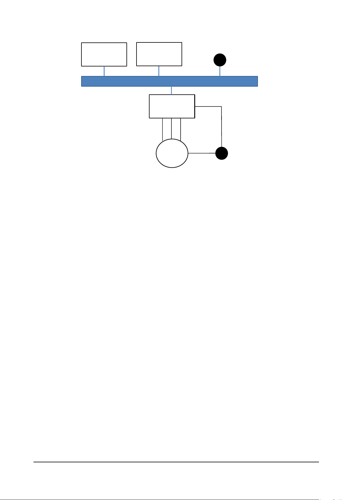
3. A STANDARD COMMUNICATION PROTOCOL ....................................................................................................... 6
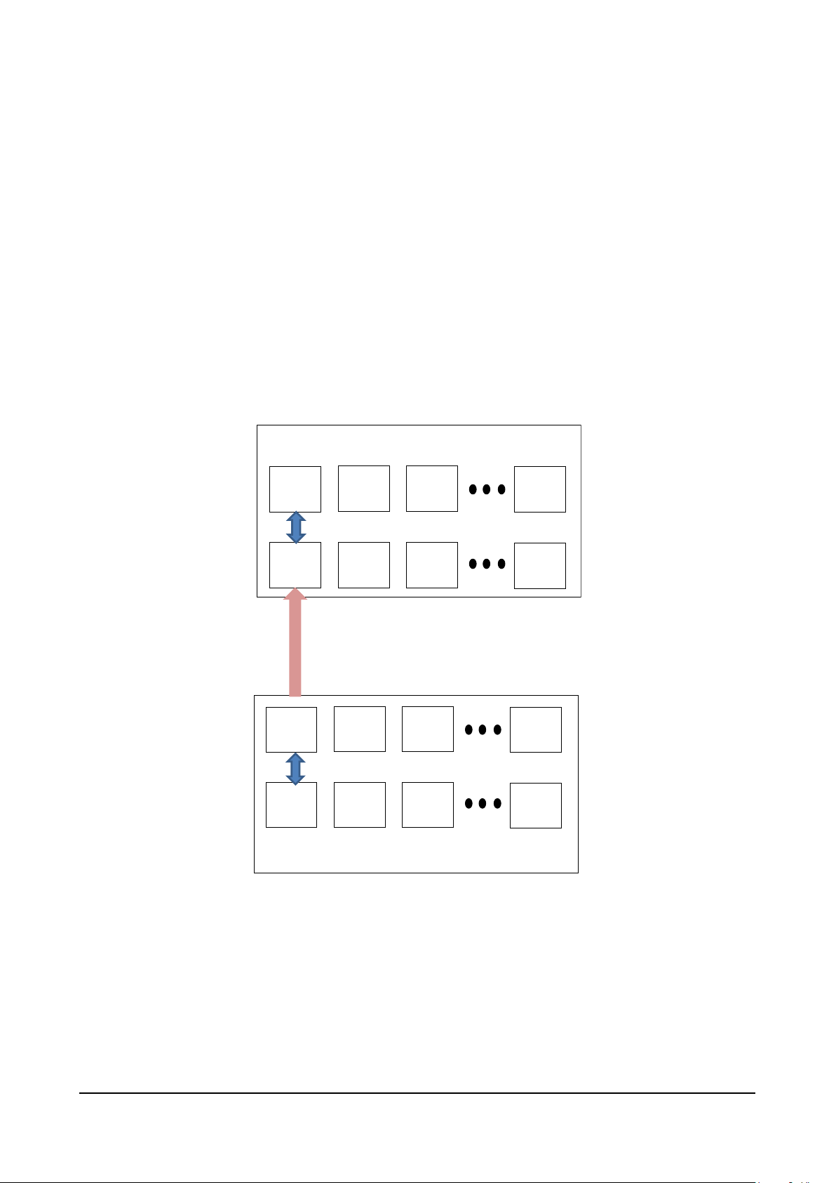
4. SHARING THE DRIVE MENU .................................................................................................................................... 8
5. FUNCTIONAL LOGIC................................................................................................................................................. 9
6. Control mode........................................................................................................................................................... 10
6.1 Speed Control ................................................................................................................................................... 10
6.2 Position Control ................................................................................................................................................. 11
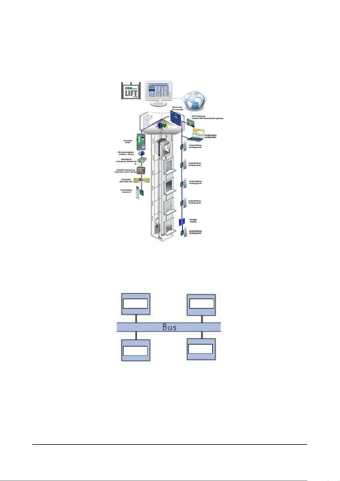
7. SUPPORTED ARCHITECTURES ............................................................................................................................ 12
8. APPLICATION OBJECTS AND PROCESS DATA OBJECTS MANAGED............................................................. 13
8.1 Process Data Object ......................................................................................................................................... 13
8.2 Application Object ............................................................................................................................................. 13
9. STATE MACHINE..................................................................................................................................................... 14
10. DRIVE CONNECTION .............................................................................................................................................. 15
10.1 Interface with Master CAN................................................................................................................................. 15
10.2 Wiring ................................................................................................................................................................ 16
10.3 Bus connection.................................................................................................................................................. 16
10.4 Bit Rates Supported .......................................................................................................................................... 17
10.5 Node IDs ........................................................................................................................................................... 17
11. INSTALLING THE APPLICATION ........................................................................................................................... 18
11.1 General ............................................................................................................................................................. 18
11.2 Requirements.................................................................................................................................................... 18
11.3 Preliminary operations....................................................................................................................................... 18
12. COMMISSIONING FROM ALPHANUMERIC KEYPAD ........................................................................................... 19
13. DESCRIPTION OF PARAMETERS.......................................................................................................................... 22
13.1 Legend .............................................................................................................................................................. 22

ADL300 CiA® 417- Description of functions and parameter list Page 4 of 46
1. INTRODUCTION
This manual contains information needed to configure the hardware and software of the ADL300 series drive (Release
3.0 and later) so that they can work in a lift system in which the various control devices communicate via a CANopen Lift
network, i.e., based on DS417 profile.
Note:
Use of the CANopen Lift requires an ADL300 version with CAN port (ADL300B-xxxx-KBL-F-4-C-yyyy
and ADL300A-xxxx-KBL-4-C-yyyy).
Communication via DS417 profile is in MdPlc environment and is therefore considered an application for all purposes.
The application is supported in all control modes provided by the drive.
The application has to be loaded via the procedure described in chapter 10.
This manual is specifically for the CANopen Lift application; for all other configurations, see the manuals ADL300 FP
”Description of functions and Parameter list” and ADL300 QS “Quick Start Guide to installation”.

ADL300 CiA® 417- Description of functions and parameter list Page 5 of 46
2. REFERENCE STANDARDS
The application conforms to the CANopen® CiA 417® specification “Application profile for lift control systems” Version:
2.0.0 of February 2, 2011, consisting of 4 parts:
•Part 1: General Definitions
•Part 2: Functions of virtual devices
•Part 3: Specifications of defined PDOs
•Part 4: Specifications of Application Objects
As an affiliated company (Vendor-ID 01000093) of CAN in Automation (CiA), WEG is constantly updated on new and
revised specifications.

ADL300 CiA® 417- Description of functions and parameter list Page 6 of 46
3. A STANDARD COMMUNICATION PROTOCOL
Civil lift systems use a complex system of operating logic and devices. To achieve the required quality and safety levels,
all devices must be able to communicate by exchanging information and commands.
Figure 1: Main Lift Control Systems
Communication must be efficient and based on a Bus architecture. CANopen Lift with CiA 417 profile is a standard
communication protocol based on a Bus architecture derived from industrial CANopen version, which allows
communication via a shared language among the various control Devices in the lift system.
Figure 2: Bus Architecture
Focusing on the part of the system composed of Control Card, Drive and Electric Motor, the Bus architecture can be
represented as follows:
Dev 1
Dev 2
Dev 3
Dev n

ADL300 CiA® 417- Description of functions and parameter list Page 7 of 46
Lift Controller Monitoring
System
Drive ADL300
M
CAN BUS
Motor Encoder
Vane Encoder
Figure 3: System architecture

ADL300 CiA® 417- Description of functions and parameter list Page 8 of 46
4. SHARING THE DRIVE MENU
The Bus architecture allows direct communication among all devices that are connected to it. The Drive implements the
Menu Sharingfunction, which displays the drive menu on the Lift Controller. Therefore, the drive can also be configured
from the Lift Controller and, in general, from any device on the bus that supports reception of information via AO 6404hex
(Modes of Operation Display) / RPDO 260.
Figure 4: Optional and standard display (Left) and Lift Controller display (Right)
In Figure 4, the drive menu is shown on the optional Drive keypad and on the Lift Controller display. At the
communication level, see the figure below.

ADL300 CiA® 417- Description of functions and parameter list Page 9 of 46
5. FUNCTIONAL LOGIC
In a lift system, the various functions (such as call control, light control, door opening control, overload control, motor
control, etc.) are performed by dedicated control devices. In the DS417 profile, the control devices perform these
functions by using applications called Application Objects (AO) installed in the device itself. In the lift system, the
Application Objects communicate with each other via DS 417 with the “homonymous” Application Objects in other
devices. Communication takes place via PDOs (Process Data Objects), which can be in Reception (RPDO) as well as in
transmission (TPDO), in which the specific application object is mapped.
The ADL300Drive, i.e., the device that controls motor direction and speed to manage car movement, uses a series of
Application Objects to manage the speed profile, control method (in speed or in position), etc. All of this information is
exchanged with the control system via RPDOs if in reception or via TPDOs if in transmission. Communication is
continuous, with intervals of 1 ms.
Each application object is therefore “mapped” in the PDO (RPDO or PDO).
The Drive state machine is controlled by the AO 6400hex (controlword). The commands that the ADL300 Drive receives
from the Lift Controller are coded in the control word.
The following is an example of communication between the Lift Controller and the Drive for management of control mode
(in position or in speed).
TPDO
259
AO
6403
hex
AO
6403
hex
RPDO
259
CANopen BUS
(DS417)
ADL300
Lift Controller
Figure 5: Block diagram for ADL300 - Lift Controller communication
The Lift Controller “commands” the control mode to the drive via AO 6403hex. To do this, the Lift Controller maps the AO
in Transmission PDO 259 and then sends the command to the Drive via the Bus. The Drive receives the command on
the “homonymous” RPDO 259 and sends it to the “homonymous” AO. The Drive has now received the command to
work in position or in speed because it has been configured by the Lift Controller.
The same Application Objects and related PDOs must be present on the Lift Controller and on the Drive for
communication to take place.

ADL300 CiA® 417- Description of functions and parameter list Page 10 of 46
6. CONTROL MODE
6.1 Speed Control
The Lift Controller configures speed control via AO 6403hex. Speed control can be in open loop (no motor encoder) or in
closed loop (with encoder on the motor).
For safety reasons, configuration is not possible when the Drive is in Enable status.
Note:
The control takes place with the multi-speeds that the controller tr
ansmits to the drive
Starting is controlled by the Lift Controller via AO 6430hex (Target Velocity), which assumes a value
other than zero. Direction is defined by the sign of the AO.
Based on the AO 6430hex target speed (expressed in multiples of mm/s) communicated to the drive
and the AO 6406hex speed reference (Control Effort) that the drive communicates to the Lift Controller,
the Lift Controller calculates and communicates to the drive the point at which to activate deceleration to
reach the destination floor. When the destination floor is reached, the Lift Controller communicates zero
speed to the drive as the new target speed, which forces the drive to stop the car. In turn, the drive
communicates to the Lift Controller that it has reached the target speed via the 10th bit of the AO
6401hex status word.
RPDO
259
TPDO
260
TPDO
262
6401
6400
6403
6430
6406
6401
6400
6403
6430
6406
TPDO
259
RPDO
260
RPDO
262
ADL 300 Lift Controller
Figure 6: Exchange messages between Drive and Lift Controller for speed control
By appropriately configuring the Lift Controller, direct arrival with speed control is possible by using the sequences
described above.

ADL300 CiA® 417- Description of functions and parameter list Page 11 of 46
6.2 Position Control
The Lift Controller configures position control via AO 6403hex. Position control can be only in closed loop (with encoder
on the motor).
The Lift Controller communicates to the Drive the AO 6420hex Target Position and the maximum speed that AO 6423hex
can reach (Profile Velocity).
Based on the AO 6420hex target position and on the position communicated by the AO 6406hex (Effort Control) drive, the
Lift Controller calculates the deceleration point for reaching the destination floor. When the destination floor is reached,
the Lift Controller communicates to drive to stop the car. In turn, the drive communicates to the Lift Controller that it has
reached the target position via status word AO 6401hex.
RPDO
259
TPDO
260
RPDO
261
TPDO
262
6401
6400
6403
6423
6406
6401
6400
6403
6423
6406
TPDO
259
RPDO
260
TPDO
261
RPDO
262
ADL 300 Lift Controller
6420 6420
Figure 7: Exchange messages between Drive and Lift Controller for position control

ADL300 CiA® 417- Description of functions and parameter list Page 12 of 46
7. SUPPORTED ARCHITECTURES
The DS417 profile requires the Drive to manage a single car with a single CAN bus. The supported architecture is shown
below:
Figure 8: CAN bus architecture with single car
Both speed and position control are available for the above architectures. In general, architectures requiring a single
CAN bus are possible. The current version of ADL300 does not support architectures requiring more than one CAN bus.

ADL300 CiA® 417- Description of functions and parameter list Page 13 of 46
8. APPLICATION OBJECTS AND PROCESS DATA OBJECTS MANAGED
8.1 Process Data Object
The current version provides the following PDOs supported by the Drive:
PDO no.
COB-ID
OBj (hex)
Type
RPDO 259 182
6400 00 6403
00 6430 00 Car Drive Unit
RPDO 261 180
6420 00
6423 00 Car Drive Unit
RPDO 263
18C
6383 01
Car Drive Unit
RPDO 2
501-527
MPDO
Generic
TPDO 260 183
6401 00
6404 00
6433 00
Car Drive Unit
TPDO 262
181
6406 00
Car Drive Unit
TPDO 2
502
MPDO
Generic
8.2 Application Object
The current version provides the following Drive Application Objects supported by the Drive:
Index (hex)
Sub-Index (hex)
Name
Access
6383
Position value
rw
6400
Controlword
rw
6401
Statusword
ro
6403
Modes of operation
rw
6404
Modes of operation display
ro
6406
Control effort
ro
641F
Position Conversion
rw
01
Number of position units
02
Total Lenght in Millimeter
6420 (*)
Target position
rw
6422 (*)
Software position limit
rw
01
Min position limit
02
Max position limit
6423 (*)
Profile velocity
rw
6430 (**)
Target velocity
rw
6433 (**)
Velocity actual value
ro
600A
1
Virtual Terminal Input
rw
2
Virtual Terminal Output
ro
(*): Profile Position / (**):Velocity Profile

ADL300 CiA® 417- Description of functions and parameter list Page 14 of 46
9. STATE MACHINE
The device works according to the following CiA 417 state machine:

ADL300 CiA® 417- Description of functions and parameter list Page 15 of 46
10. DRIVE CONNECTION
10.1 Interface with Master CAN
Figure 9: CAN connector position
Figure 10: Safety connections for control with a single contactor

ADL300 CiA® 417- Description of functions and parameter list Page 16 of 46
10.2 Wiring
The connection is made on the CAN contactor and does not require a power supply. The interface is functionally isolated
(>1kV).
See Paragraph 7.5 in Quick Start manual
LSH H
CAN connector (XC)
Prg
Enter
BRK n=0ILIMENCNT AL
CAN
CAN LED
Terminal
Designation
Function
Wire section
L
CAN_L
CAN_L bus line (low dominant)
0,2 ... 2,5 mm2
AWG 26 ... 12
SH
CAN_SHLD
CAN shielding
H
CAN_H
Can_H bus line (high dominant)
LED
Significance
CAN (green)
Off
Stop
Flashing
Pre-operative state
On
Operative state
Figure 11: CAN interface
10.3 Bus connection
The Bus connection requires a shielded twisted pair (as per the CANopen specification) placed separately from the
power cables (minimum distance 20 cm). The cable shielding must be grounded at the two ends. If the cable shieldings
are grounded at several points of the system, use unipotential connection cables to reduce the current flow between the
Drives and the master CAN bus.
Note:
Note on terminations: the first and last element in the network must have a 120 ohm resistor between
pins L and H.
CAN-H
MASTER
CANopen
L
ADL300
SH H
CAN (XC)
L
ADL300
SH H
CAN (XC)
CAN-L
Other
DS417
Product
Figure 12: CAN BUS connection
Maximum cable length is 200 meters (6 meters for peripheral cable sections).

ADL300 CiA® 417- Description of functions and parameter list Page 17 of 46
10.4 Bit Rates Supported
The CAN bus default speed is 250kbit/s. It can also be configured at 125kb/s (menu 22 parameter 4004).
10.5 Node IDs
Each device connected to the Bus has a unique network ID. The Drive’s default ID is 2 (this address can be changed via
parameter 4006 menu 22).

ADL300 CiA® 417- Description of functions and parameter list Page 18 of 46
11. INSTALLING THE APPLICATION
11.1 General
The preliminary operations for commissioning are describe in chapter 8 of the ADL300 QS manual.
11.2 Requirements
The DS 417 application for ADL300 requires firmware version 3.00 and later.
To install the application you need a PC, WEG GF Express software version 1.8 or later with Catalog, a connection cable
to the RS-232 drive, and the setup CD.
The CD for installing the application contains an automatic procedure that copies the required files to the specific folder
of the GF Express catalog. When installation is done, the setup procedure requests the following files / path:
Files containing DS417Application:
• ADL300Asy_3_7_10_Fw_Lang_DS417_1_5_21_0__A2.fl2 (EPC for Synchronous Motors)
• ADL300Syn_3_7_10_Fw_Lang_DS417_1_5_21_0__ A2.fl2 (EPC for Asynchronous Motors)
11.3 Preliminary operations
The drive can contain two applications (“Application 1” and “Application 2”). You can download the DS417 application to
“Application 2.”
Files to be installed:
• ADL300Asy_3_7_10_Fw_Lang_DS417_1_5_21_0__A2.fl2 (EPC for Synchronous Motors)
• ADL300Syn_3_7_10_Fw_Lang_DS417_1_5_21_0__ A2.fl2 (EPC for Asynchronous Motors)
Refer to parameter menu 4.5 PAR 558 Application select to select which application to run.
When the application has been installed, do as follows:
1) Send the “Drive reset” command via WEG_eXpress.
2) Execute the “Load default drive values” command
3) Execute the “Save parameter into target” command
4) Execute the Drive reset command.
The application is now ready for use. The parameters are shown on menu 5 “LIFT”.

ADL300 CiA® 417- Description of functions and parameter list Page 19 of 46
12. COMMISSIONING FROM ALPHANUMERIC KEYPAD
Commissioning from the keypad is also possible with the CiA 417 application.
12.1 Asynchronous motor: guided startup
From ADL300 Quick Start Guide (pages 48/80 for asynchronous, pages 55/80 for brushless)
GUIDED STARTUP is a procedure for quick commissioning of the Drive that helps you set the main parameters.
It consists of a series of questions corresponding to the various sequences for insertion and calculation of the
parameters required for correct operation of the Drive and the Lift application. These sequences are in the following
order:
●Electrical connections See step 1 (QS guide)
●Setting motor data See step 2 (QS guide)
●Self-learning with motor stopped or coupled to load See step 3 (QS guide)
●Setting encoder parameters See step 4 (QS guide)
●Setting maximum speed reference value and maximum system speed
See step 6 (QS guide)
●Setting system weight See step 7 (QS guide)
●Setting application parameters See step 8
●Saving parameters See step 9
12.2 Synchronous motor: guided startup
●Electrical connections See step 1 (QS guide)
●Setting motor data See step 2 (QS guide)
●Self-learning with motor stopped or coupled to load See step 3 (QS guide)
●Setting encoder parameters See step 4 (QS guide)
●Encoder phasing See step 5 (QS guide)
●Setting maximum speed reference value and maximum system speed
See step 6 (QS guide)
●Setting system weight See step 7 (QS guide)
●Setting application parameters See step 8
●Saving parameters See step 9

ADL300 CiA® 417- Description of functions and parameter list Page 20 of 46
Step 8 Setting application parameters:
… for asynchronous and synchronous motor
t
SEQ
01 PAR: 11040
Accel initial jerk
0.500
m/s3
Valore: 0.500
t
SEQ
02 PAR: 11042
Acceleration
0.600
m/s2
Def: 0.600
t
SEQ
03 PAR: 11044
Accel initial jerk
1.400
m/s3
Def: 1.400
t
SEQ
04 PAR: 11046
Decel initial jerk
1.400
m/s3
Def: 1.400
t
SEQ
05 PAR: 11048
Deceleration
0.600
m/s2
Def: 0.600
Table of contents
Other WEG Industrial Equipment manuals
Popular Industrial Equipment manuals by other brands

morse
morse 2-300 Series Operator's manual

schmersal
schmersal MZM 100 AS operating instructions

PCB Piezotronics
PCB Piezotronics ICP 320C15 Installation and operating manual

Mapal
Mapal Hydro Mill Chuck Installation and operating instructions

Siemens
Siemens 3RS17 Series operating instructions

CAVIDYNE
CAVIDYNE CaviBlaster 1030-ROV Operation & maintenance manual

Trelleborg
Trelleborg SCN 2250 Handling, Storage, Installation and Maintenance Manual

Vertiv
Vertiv Liebert XDU 060 Installer/user guide

ABB
ABB HT587010 Operation manual

Asco
Asco P152 Series Installation and maintenance instructions

Bishamon
Bishamon Blue Label BM20 Operation and service manual

PASCO
PASCO ME-8089 instruction manual