Wega Wegaconcept User manual

REV. DATA REALIZZ. CONTROLL. APPROV. PAG. MODIFICA
00 03/2011 L. Bottega Tutte Emissione manuale
01 05/2013 Bottega/Chies Tutte Aggiornamento software

4
Wegaconcept
Technical manual
Index
1 Technical characteristics ................................................................ 8
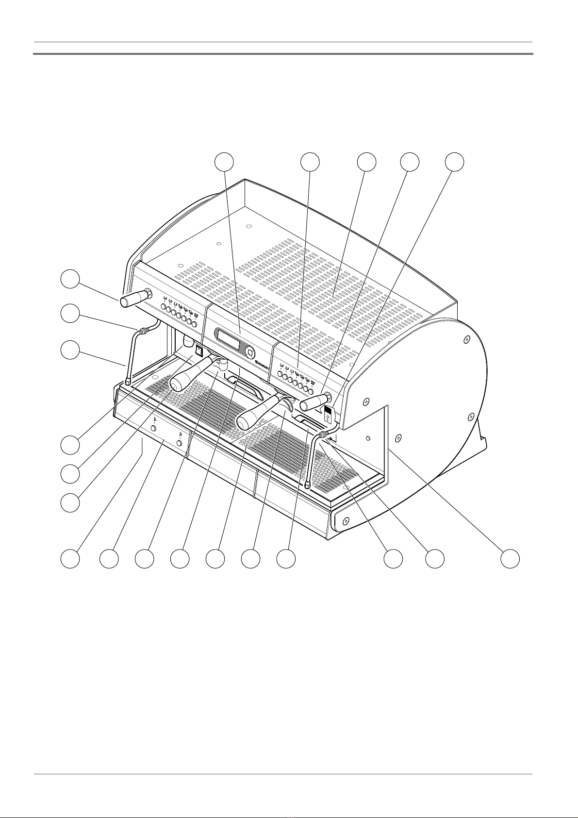
1.1 External components .......................................................... 8
1.2 Internal components........................................................... 9
1.3
Specications............................................................................................10
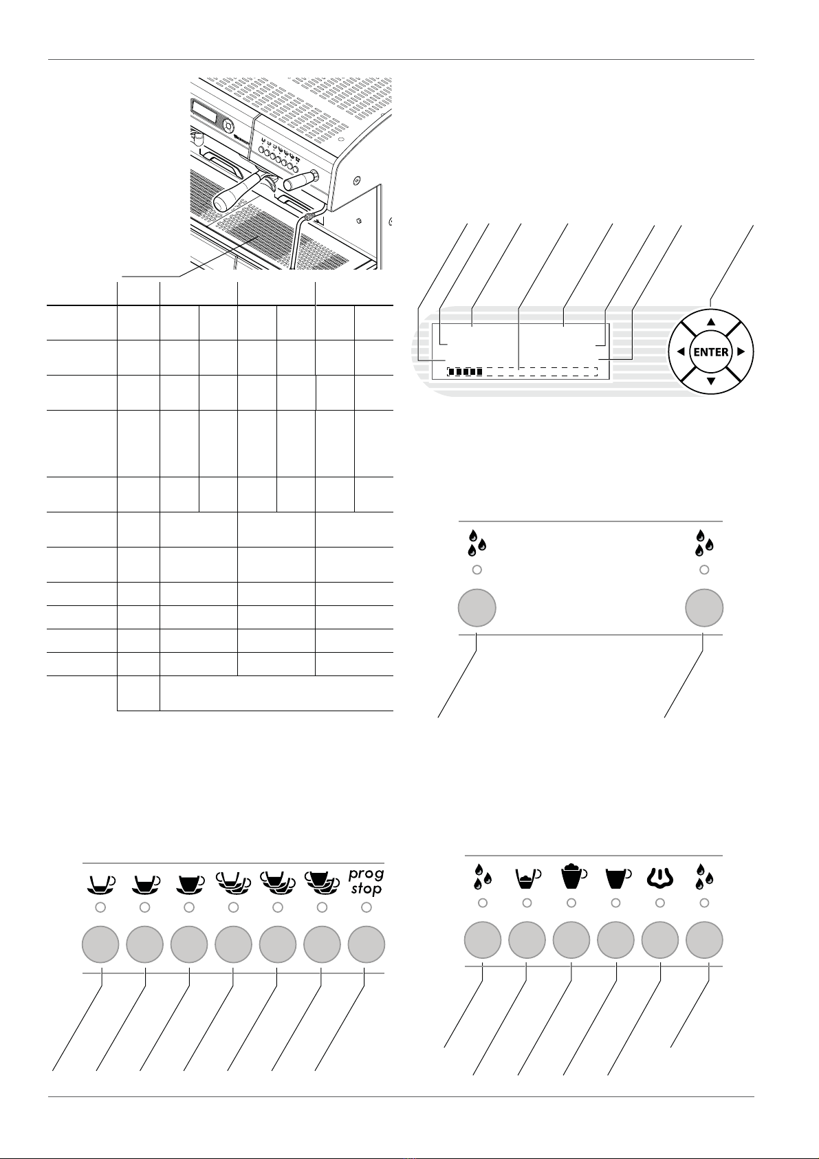
1.4 Push-buttons panels........................................................... 10
2 Preparation.................................................................................... 11
2.1 Unpacking the machine ...................................................... 11
2.2 Equipment preparation ..................................................... 11
3 Machine installation...................................................................... 12
3.1 Positioning ........................................................................ 12
3.2 Hydraulic connection .......................................................... 13
3.3 Wiring................................................................................. 14
3.4 Turning on the machine...................................................... 14
3.5 External motor pump adjustment....................................... 15
3.6 Machine tune-up ................................................................ 15
4 Boilers............................................................................................ 16
4.1 Coee boiler........................................................................ 16
4.2 Services boiler..................................................................... 16
5 Dispensing assembly ..................................................................... 16
6 Automatic Water Entry.................................................................. 17
7 Volumetric dosing.......................................................................... 17
8 Pressure switch.............................................................................. 17
9 Anti-ooding device...................................................................... 17
10 Pumping system............................................................................ 18
11 Valve group.................................................................................... 18
11.1 Pressure limitation safety valve........................................... 18
11.2 Expansion valve- non-return valve...................................... 18
12 Electric control unit........................................................................ 18
13 Thermostat.................................................................................... 18
14 Cup heating device ........................................................................ 19
15 Softeners ....................................................................................... 19
15.1 Regeneration of the softener .............................................. 19
15.2 Regeneration notication and counter reset ....................... 20
16 Dispensing compartment light and illuminated sides.................... 20
17 Preparation of beverages............................................................... 21
17.1 Programming the coee doses............................................ 21
17.2 Coee preparation .............................................................. 21
17.3 Programming the hot water doses...................................... 21
17.4 Hot water delivery............................................................... 22
17.5 Regulation of the hot water temperature ........................... 22
17.6 Steam delivery.................................................................... 22
18 Cappuccino maker ......................................................................... 23
18.1 Installation.......................................................................... 23
18.2 Cleaning.............................................................................. 24
18.3 Cappuccino.......................................................................... 24
18.4 Warm milk .......................................................................... 24
19 Autosteamer.................................................................................. 24
19.1 Description.......................................................................... 24
19.2 Automatic heating and foaming ......................................... 25
19.3 Automatic heating .............................................................. 25
19.4 Manual heating and foaming.............................................. 25
19.5 Automatic autosteamer nozzle cleaning. ............................ 25
19.6 Autosteamer system operation ........................................... 26
20 Energy Saving ............................................................................... 27
20.1 Description.......................................................................... 27
20.2 Energy savings programming.............................................. 27
20.3 Programming of group stand-by......................................... 27
21 Group washing .............................................................................. 27
22 Cleaning ........................................................................................ 28
23 Checks and maintenance............................................................... 29
23.1 Control and maintenance operations .................................. 29
23.2 Scheduled assistance .......................................................... 31
23.3 Grinders wear check............................................................ 32
24 Malfunctions and related solutions................................................ 32
25 Alarms and display indications ...................................................... 35
25.1 Display indications.............................................................. 35
25.2 Alarms................................................................................. 35
26.List of hazards................................................................................ 37
27 USB drive ...................................................................................... 38
27.1 Data saving ......................................................................... 38
27.2 Restoring data..................................................................... 38
27.3 Software Update................................................................. 38
28 Programming ................................................................................ 39
28.1 Access to the programming................................................ 39
28.2 Browser key......................................................................... 39
28.3 Programming menu............................................................ 40
28.4 Boiler pressure adjustment. ................................................ 40
28.5 Adjustment of coee water temperature. ........................... 41
28.6 Adjustment of the groups temperature............................... 41
28.7 Adjusting the cup heater temperature ............................... 42
28.8 Programming of Energy Saving time and groups stand-by. 42
28.9 Conguration of groups proper use..................................... 43
28.10 Standby mode..................................................................... 44
28.11 Autosteamer option............................................................ 45
28.12 Softener regeneration......................................................... 46
28.13 Display of the counters........................................................ 46
28.14 Setting the date .................................................................. 47
28.15 Setting the working days .................................................... 48
28.16 Setting the language .......................................................... 48
28.17 Delivery check..................................................................... 49
28.18 Programming group washing ............................................. 50
28.19 Setting the number of active groups................................... 51
28.20 Loading the default data..................................................... 51

5
Wegaconcept
Technical manual
ENGLISH
29 Water meter................................................................................... 51
29.1 Viewing of the litres of water used...................................... 51
29.2 Resetting the litres of water used........................................ 51
30 Schedules maintenance................................................................. 52
30.1 Alarm display...................................................................... 52
30.2 Scheduled assistance .......................................................... 53
30.3 Grinders wear check............................................................ 54
31 Machine serial programming......................................................... 56
32 Data reset ...................................................................................... 56
32.1 Resetting of selection counters ........................................... 56
32.2 Alarm reset ......................................................................... 57
32.3 Resetting groups washing counter...................................... 57
32.4 Water liters count for softener regeneration reset............... 57
32.5 Cycle count for planned service reset................................... 57
32.6 Ground coee kg count reset............................................... 57
33 Electric diagrams ........................................................................... 58
33.1 Electronic control unit diagram ........................................... 58
33.2 Electronic control unit Diagram Rev. 01............................... 60
33.3 Power supply electronic diagram ........................................ 62
33.4 Connectors electric diagram................................................ 63
33.5 Control unit display / CPU diagram...................................... 67
34 Hydraulic diagram ......................................................................... 68
35 Credit - Debit / Debit - Credit system .......................................... 70
35.1 Credit - Debit system with direct connection to the register 70
35.2 Debit - Credit system with direct connection to the register 70
35.3 Debit - Credit system with connection to the INTERFACE .... 72

6
Wegaconcept
Technical manual
AGeneral Warnings
The manufacturer of the equipment cannot be held
responsible for damage caused by failure to oblige to
the requirements below.
BWarnings for the installer
t Read this manual carefully. It provides important
information on safe installation, operation and main-
tenance of the equipment;
t Installation, conversion to other type of gas, and
maintenance of the equipment must be carried out
by personnel qualied and authorized by the manu-
facturer, in compliance with safety regulations and
instructions included in this manual;
t identify the model of the equipment. The model is
shown on the packaging and on the nameplate of
the machine;
t Install the equipment only on sites where there is
good ventilation;
t Do not obstruct the ventilation and exhaust holes on
the machine;
t Do not tamper with the equipment components.

8
Wegaconcept
Technical manual
1Technical characteristics
1.1 External components
1. Cup heater surface.
2. Push-button panel for co ee selections.
3. Display and browser key.
4. Machine power switch.
5. Steam knob.
6. Anti-burn seal.
7. Steam nozzle.
8. Tray and cup support grille.
9. Pull-out cup support grille.
10. Lit up side.
11. Filter holder.
12. Hot water delivery nozzle.
13. Steam delivery nozzle / autosteamer (*).
14. Adjustable foot.
15. Push-button panel for services/ autosteamer (*).
16. Dispensing spouts.
17. Dispensing compartment light.
18. USB socket.
1 5 182
13
6
5
107 68 91514
11
12
4
16 1617
3
(*) optional.

9
Wegaconcept
Technical manual
ENGLISH
1.2 Internal components
1. Services boiler pressure switch.
2. Services boiler.
3. Coee boiler pressure switch.
4. Internal motor pump (if included).
5. Dispensing group.
6. Water inlet connection.
7. Hot water mixer.
8. Drain pad.
9. Volumetric dosing device.
10. Coee water container.
11. Coee water heating element.
12. Electronic control unit.
13. Services boiler heating element.
2
13
11
5
3
4
89
12
10
6
7
1

10
Wegaconcept
Technical manual
1.3
Specications
The nameplate of
the machine is fixed
on the base of the
frame under the drain
pan.
Technical
data plate
Technical data table
1.4 Push-buttons panels
Push-button panel for coee.
The push button panel is connected to the electronic
control unit, and allows selection and programming of
the doses of coee and tea.
Services push button panel
The services push button panel is included with
the machine, it is connected to the electronic control
unit and allows the delivery of hot water for making
beverages such as tea, etc...
Services push-button and autosteamer (*)
The autosteamer push-button panel is installed with
the homonymous device, and allows selection and
programming of milk-based beverages.
It also includes the services push button panel
Display and browser key.
All programming operations of the machine are
carried out using the selector as specied in the chapter
"28 on programming".
Alongside the selector there is a display which shows
the operating data of the machine and the programming
messages.
Groups 2Gr 3Gr 4Gr
Power supply
voltage V 230/400 240/415 230/400 240/415 230/400 240/415
Total power W 4.400 4.790 5.600 6.100 7.100 7.730
Power x group W 150x2 165x2 150x3 165x3 150x4 165x4
Coee water
tank heating
element power
per group
W 1.000x2 1.090x2 1.000x3 1.090x3 1.000x4 1.090x4
Steam boiler
power W 3.000 3.270 3.000 3.270 5.000 5.445
Steam boiler
capacity lt / UK gal 8 / 1,76 13 / 2.86 13 / 2.86
Coee water
tank capacity lt / UK gal (1,2/ 0,26)x2 (1,2/ 0,26)x3 (1,2/ 0,26)x4
Width mm / in 800 / 31.5 1040 / 40.9 1280 / 50.4
Depth mm / in 580 / 22.8 580 / 22.8 580 / 22.8
Height mm / in 590 / 23.2 590 / 23.2 590 / 23.2
Net weight kg / lb 95 / 209 117 / 257 142 / 312
Operating
conditions °C / °F 5 ÷ 40 / 41 ÷ 104
1 Espresso
1 Medium coee
1 Long coee
2 Espressos
2 Medium coees
2 Long coees
Stop / Programming /
Continuous
1,2 Bar Press 0,0
08:30 10-FEB-2011
Umidità 62% P 32%
Pressione caldaia
Tasto navigatore
Pressione
circuito idraulico
Indicatore potenza
assorbita
Ora
Umidità ambiente
Data
Potenza assorbita
istantanea
Hot water dose 2
Hot water dose 2
Hot water dose 1
Hot water dose 1
Small dose autosteamer
Large dose autosteamer
Automatic heating
Manual steam +
foaming
(*) optional.

11
Wegaconcept
Technical manual
ENGLISH
2Preparation
2.1 Unpacking the machine
Open the packaging, ensuring not to damage the
machine.
Remove the machine protections and the equipment
contained in the package. Take the machine out.
If there is an external motor pump, the motor and the
pump are provided in a separate package.
Screw the steam nozzles to
the taps.
Motor pump
For the machines with an external motor, it is
necessary to prepare the pump and the motor.
Assemble the 3/8 gas connection with the inlet lter
(2) of the pump (arrow ª) and the plain 3/8 outlet gas
connection (1) of the pump (arrow ©).
Use the special washers (3) provided for sealing
purposes.
To correctly couple the pump and motor, use the
appropriate joint (4) and the spacer ring (5), lock
everything with the two clamps (6).
The pump and motor joint has to be installed also on
the machines with an internal motor pump.
2.2 Equipment preparation
Filter holder
In the housing of the lter holder (1), place the spring
to stop the lter (2).
Take the two cups (3) or one-cup (4) lter and press
it rmly into the lter holder.
Spouts
Complete the lter holder by installing the two-cup
(6) or one-cup (5) spout.
Softener
The softener is supplied by default.
On request, an automatic resin
softener is supplied.
For further information, refer to
chapter 15 "Softeners".
1 2
3
6456
5
1
6
2
3 4
3
!Install the spout with relative lter: one-cup spout
on one-cup lter holder or with one-cup lter, etc...
!Install the connection with the inlet lter (2) of the
pump (arrow ª).

12
Wegaconcept
Technical manual
3Machine installation
3.1 Positioning
Prepare an ample support base for the machine that
is suitable to support its weight (3).It is important for all
terminals of connections to the water mains (12) and to
the electrical mains (9) to be easily reachable and in any
case in the immediate vicinity of the machine.
Make sure that there is sucient space for placing
and correctly using the appliance. The grinding-dosing
machine (4) must be placed in the immediate vicinity
of the appliance in order to allow for comfortable use
of the machine.
5
4
3
2
1
12
14
13
11
15
10
9
8
6
7
!For correct operation, the machine must rest on a
perfectly horizontal surface. Any alignment of the
machine must be done by adjusting the feet (8).
It is advisable to equip the working base of the
machine with a drawer (1) for used coffee grounds,
preferably with a rubber device (2) for tapping the lter
holder.

13
Wegaconcept
Technical manual
ENGLISH
3.2 Hydraulic connection
t Remove any rubber plugs which may be inserted in
the tap xtures of the softener;
t connect the water supply (12) to the softener inlet
(10) using the provided exible hose;
t rinse the resins from the softener and check that the
water, which initially comes out yellowish, comes
out clean;
t connect the softener outlet (11) to the external motor
pump inlet (13);
t connect the outlet of the motor pump (14) to the inlet
of the machine (7);
t connect the drain pad of the machine (6) to the sewer
discharge (5) using the special hose provided, avoid-
ing overly tight bends or kinks, and making sure that
there is sucient inclination for water to drain.
Warnings
1. The water supply must provide cold water for
human consumption (potable water) at a pressure
between 1,5 and 5 bars. If the pressure is higher than
5 bar, connect a pressure reducer before the pump.
2. add a tap (15) to the water supply so as to stop water
from owing to the machine;
3. in order to prevent damage, it is advisable to install
the softener where it will be protected from accidental
blows;
4. to prevent water from freezing, install the softener
inside a premise with a room temperature higher
than 5°C;
5. if there is no softener, connect the water supply (12)
directly to the inlet of the external motor pump (13);
6. if there is an internal motor pump, connect the outlet
of the softener (11) (if there is one) or the water supply
(12) directly to the machine inlet (7);
7. when connecting the pad of the machine to the sewer
drain, avoid overly tight curves or kinks, and make
sure that there is sucient inclination for water to
ow out of the drain.
8. the drain must be connected to an inspectable siphon
that can be periodically cleaned, in order to avoid
bad odours;
9. to avoid oxidization and damage to the machine over
time, do not use iron connections for the hydraulic
system, even if galvanized.
!All lling connections are 3/8 male gas type. The
drain pan is connected to a tube with an internal
diameter of 16mm.
!The water supply of the appliance must be carried
out with water which is suitable for human
consumption, in compliance withthe regulations in
force in the place of installation.The installer must
receive, from the owner/manager of the system,
conrmation that the water meets the above listed
requirements.
!
During the installation of the appliance, only the
components and materials supplied with the
appliance are to be used. Should the use of other
components be necessary, the installer must verify
their suitability to be used in contact with water
used for human consumption. The installer must
carry out the hydraulic connections in accordance
with the hygiene norms and the hydraulic safety
norms for environmental protection in force in the
place of installation.
!The hydraulic connection must be made in
compliance with local national standards. In case
of use of an external tank: the connection hose
between the machine and the tank can't be longer
than 150 cm. For the European Community: both
for the hydraulic connection to the water supply,
and for the connection to an external tank, it is
necessary to place a non-return valve (16) on the
machine as set forth by EN 1717 standards.
!All of the machines are equipped with a "Time-out"
device that allows filling of water in the boiler
within a maximum time. This function keeps water
from owing out of the boiler's valve (ooding)
and keeps the motor pump from overheating. If
the time limit is not enough for the boiler to ll up
completely (such as for the machines installed with
3 or 4 groups), turn the machine o and then back
on, and repeat the operations listed above.
!FOR THE U.S.A. -The water connections and
discharges must be made in accordance with
the 2003 International Plumbing Code of the
International Code Council (ICC), or with the
2003 Uniformed Hydraulic Code of the IAPMO.
The machine must be installed together with an
adequate non-return valve, as required by national
regulations.

14
Wegaconcept
Technical manual
3.4 Turning on the machine
Before turning on the machine, make sure the drain
pad (2) located under the cup support grid is correctly
connected to the sewer.
Turn on the machine using the main switch (1) and
follow the indications on the display of the machine.
C Motor pump power cable
MP Motor pump terminal
B Blue
M Brown
GV Yellow-green
C
MP
BB
MM
GV GV
3.3 Wiring
It is necessary to link a safety main
switch (A) on the electric panel, as
required by standard regulations.
Machine with INTERNAL MOTOR PUMP
In case of internal motor pump connect the power
cable as set forth in the chapter 33 "Electrical diagrams"
(the cable has a cross-section and number of wires based
on the power and voltage of the machine).
Machine with EXTERNAL MOTOR PUMP
In case of external motor pump, proceed as follows:
1. Connect the motor pump cable (with smaller cross
section) to the connector of the external motor as
shown in the diagram below.
2. Connect the machine power cable (with larger
cross section) as set forth in the "Wiring diagrams"
chapter.
A
1
2
When the machine
is turned on, it performs
the functional test and
reports information
regarding the software
installed.
t XX.XX.XXXX : revision date
t RY : revision number
If the result is O.K.
the machine is working
correctly.
In case of negative
result, check the
message on the display.
FUNCTIONAL TEST
DELNEW XX-XX-XX RY
D.ELITE
TEST
-O.K.-
!
t To avoid the risk of burns, it is advisable to keep
hands away from the hot water nozzle, steam
nozzleanddelivery groupsduringthe machine's
heating phase.
t Before using the machine, run deliveries dry
with the lterholder attached for afewseconds
to release any air which may be in the circuit.
t Before using the machine, dispense a few
servings of coee to test the grinding and to
check the operating pressure of the machine.
!Always connect the motor pump cable before the
machine power supply cable, in accordance with
the diagram provided. Failure to comply with
the instructions given above may cause serious
damage to the machine and/or motor pump and
will invalidate the warranty. Carry out the electrical
connections only when the machine isdisconnected
from the power supply.

15
Wegaconcept
Technical manual
ENGLISH
3.5 External motor pump adjustment
To adjust operating pressure proceed as follows:
t Operate a coee delivery switch;
t adjust the pressure by turning the screw located on
the pump (1) so as to obtain a value between 8 and
9 bar: tightening the
screw increases the
pressure, and loosen-
ing it reduces the pres-
sure. check the pres-
sure on the display (2);
t turn off the delivery
switch.
3.6 Machine tune-up
When installation is complete, the appliance has to be
started, brought to the nominal working condition and
left for 30 minutes in the "ready to operate" condition.
Afterwards, the appliance has to be turned o and
emptied of the first water introduced in the whole
hydraulic circuit, to eliminate possible initial impurities.
Then, the appliance must be once again loaded and
brought to the nominal working conditions.
After having reached the "ready to operate" condition,
the following operations have to be performed:
a) for each coffee unit, carry out a continuous
delivery, in order to release at least 0.5 liters of the
coee circuit. In the case of several dispensing points
matched with the same exchanger/coee boiler, divide
the volume on the base of the number of the dispensing
points;
b)
release the whole volume of hot water inside the
boiler (6 liters for 2GR, 8 liters for 3GR, 11 liters for 4GR), by
performing a continuous delivery from the appropriate
nozzle. In the case of several dispensing points, divide
the volume on the base of the number of the dispensing
points;
continuously release steam for at least 1 minute
for each steam dispensing point.
1
When the machine
is turned on, it will
activate the motor
pump installed and
begin to ll the services
boiler and the water
heaters for the coee (equal to the number of delivery
groups installed on the machine).
0,0 Bar Press 3,5
08:30 14-APR-2010
COFFEE
WATER FILLING
In order to remove
the air from the
heaters, each time the
machine is turned on
the solenoid valves
of the groups will be
activated, making water and steam come out from the
perforated disk of each group for about 10 seconds.
When the heating
phase of the delivery
groups has finished
(after about 10
minutes), signaled by
the disappearance of
the “PLEASE WAIT” indication, it will be possible to
make the coee selections. For the delivery of hot water
and steam, it will be necessary to wait for the complete
heating of the services boiler.
During the heating
phase of the services
boiler (from 95°C to
98°C), the machine will
execute a light delivery
of water and steam
from the hot water nozzle.
The delivery
of steam and hot
water, and thus the
full operation of the
machine, will be
possible only at a
pressure higher than 0.6 bar.
0,0 Bar Press 3,5
PLEASE WAIT
Humidity' 38% P 85%
0.7 Bar Press 3.5
08:30 14-APR-2010
Humidity' 38% P 85%
0,0 Bar Press 3,5
STEAM ESCAPE
humidity' 38% P 85%
0,0 Bar Press 3,5
08:30 14-APR-2010
MAKE ATTENTION
WATER/STEAM ESCAPE
0,0 Bar Press 3,5
8:30 14-APR-2010
2
!To avoid the risk of burns, it is advisable to keep
hands away from the hot water nozzle, steam
nozzle and delivery groups during the machine's
heating phase.

16
Wegaconcept
Technical manual
5Dispensing assembly
The delivery group is composed as follows :
the group body (1) is made up of a metallic block
which is hooked onto the coee boiler (2);
t the activation of the motor pump and solenoid valve
(3) located on the side of the group allows the cold
water to enter the boiler (4), consequently the hot
water in the boiler is carried towards the delivery
group (5);
t the electrical cartridge heating element (6) installed
in the group is controlled by an electronic control unit
and allows the group to be heated at a programmed
temperature;
t the temperature sensor (7) detects the value of the
temperature of the group and sends it to the elec-
tronic control unit;
t the activation of the safety thermostat (8) prevents
risks if there is a failure in the electronic system
4Boilers
There are two kinds of boilers inside the machine:
4.1 Coee boiler
Each delivery group is equipped with a coee boiler
(1)of limited capacity (1,2
litres).
These boilers provide
hot water for the coee.
Heat is provided by an
electric heating element
(2).
The boilers include a
temperature sensor (3) and
a safety thermostat (4).
4.2 Services boiler
Inside the coee machine, there is a services boiler (5).
This boiler provides steam and hot water for tea.
Heat is provided by an electric heating element (6).
The boiler includes a temperature sensor (7), a safety
valve (8), a level probe (9a) and a safety probe (9b).
9a
6
5
9b
7
8
8
2
3
1
3
7
1
6
4
5
4 3
2
1
! Do not replace the heating element with a more
powerful one. Before making any modications, contact the
manufacturer.

17
Wegaconcept
Technical manual
ENGLISH
6Automatic Water Entry
The Automatic Water Entry system is for checking the
boiler level. It is composed of:
t level probe (short) (1)and safety probe (long) (2) in-
serted in the boiler, composed of a stainless steel rod;
electronic control unit (3) ;
t hydraulic circuit controlled by
a motor pump and a solenoid
valve controlled by the elec-
tronic control unit.
When, during the normal
operation of the machine, the water
level drops down, the level probe
(1) sends a signal to the electronic
control unit (3), which activates the motor pump and the
lling solenoid valve, thus restoring the level of water in
the boiler.
If the level is very low or there is no water in the boiler
(during the machine's installation or due to a failure),
the safety probe (2) sends a signal to the control unit
which de-activates the heating element to keep it from
overheating and activates the motor pump and the
solenoid valve to restore the level of water in the boiler.
To avoid possible flooding due to machine
malfunctions or leaks in the hydraulic circuit, the
electronic control unit includes a timing device that cuts
o automatic lling after a maximum operating time
(roughly 30 seconds). During the installation of machines
with three or four groups the initial water lling time
may exceed the established time limit. In this event,
just switch the machine o and then back on to restore
normal operating conditions.
1
2
7Volumetric dosing
The volumetric dosing device serves the purpose of
measuring the quantity of water sent to the group of
espresso delivery.
The dosing device
generates an electrical
impulse which is sent to the
electronic control unit.
This impulse is read by the
control unit and memorized
during the programming of
the dose.
The ashing of the LED (1)
indicates that the electrical impulse has been sent from
the dosing device to the control unit.
8Pressure switch
The machine includes two types of pressure switches:
COFFEE BOILER PRESSURE SWITCH
Each coffee boiler is equipped with a
pressure switch to control the pressure.
Calibration is set to 5 bar and can be
distinguished by the green seal.
SERVICES BOILER PRESSURE SWITCH
also the boiler is equipped with a pressure
switch to control the pressure.
Calibration is set to 1.5 bar and can be distinguished
by the red seal.
9Anti-ooding device
The cover installed on the pressure relief valve
makes it possible to collect any water which may
leak from the boiler
due to malfunction
and channel it to the
drain pad, by means
of a special hose.
3
1

18
Wegaconcept
Technical manual
10 Pumping system
This is a component that
feeds the machine, raising
the water pressure to 8-9
bar for coee delivery and
automatic filling of the
boiler.
11 Valve group
The valves are devices whose purpose is to ensure the
safety and proper operation of the machine.
11.1 Pressure limitation safety valve
The pressure relief valve guarantees that the pressure
in the boiler does not go above 2 bar. If there is a
malfunction, the capacity of the valve is such that it can
eliminate all the excess pressure from the boiler.
11.2 Expansion valve- non-return
valve
This is a valve consisting of an expansion
valve and a non-return valve.
t Expansion valve (1): the cold water sent
from the pump to the heat exchangers
is heated. This heating causes an
increase in the volume of water.
To limit pressure increases in the
hydraulic circuit, the valve limits
the maximum internal pressure of
the circuit to 12 bar.
t non-return valve (2): Its function
is that of preventing the back ow
of water from the exchangers in
the hydraulic circuit.
12 Electric control unit
The electronic control unit is the nerve centre of
the machine. It monitors and controls all
operation of the unit.
The information related to the installed
software (date and version) can be seen on
the display when the machine is turned
on. The monitoring and control of the
entire functioning of the machine.
The information concerning the
installed software (date and version) can
be seen on the display when the machine is turned on.
13 Thermostat
The thermostat allows you to avoid damage to the
electrical resistance in case of lack of water in the boiler.
The thermostat bulb (7) is located inside a sheath (8)
placed at the center of resistance. The contacts of the
thermostat (9) are connected to the electrical resistance
(10). If the electrical resistance is exposed due to failure
to load water to the boiler, the temperature of the
resistance increases dramatically. At this point, the
thermostat interrupts the power supply to the resistance
thus preventing damage.
1
2
11
9
710
8
DATI
REGISTER RESET
!When the software is updated, as soon as the
machine is started the system loads the default
data. In this case you will need to set the machine
parameters again.
!To reset the thermostat, press the center button
(11). However, before trying to operate the
machine, verify the causes of the blockade of the
water feeding the boiler.

19
Wegaconcept
Technical manual
ENGLISH
1
Cup heater
ON/OFF
14 Cup heating device
The cup heating device is for heating cups before
they are used.
Place the cups to be heated on the appropriate
surface (1).
To turn on the cup heater, press
the () navigator button (it is not
necessary to insert an USB drive); an
asterisk will appear on the rst line on
the far right of the display, indicating
that the cup heater is ON.
To turn it off, press the ()
navigator button again, the asterisk
will disappear.
To change the temperature of
the cup heater, proceed as listed in
chapter "28-Programming".
15 Softeners
Mains water contains insoluble salts, which cause the
build-up of lime scale deposits in the boiler and other
parts of the machine. The softener makes it possible
to eliminate or substantially reduce the presence of
these mineral salts. The resin softener has the property
of retaining the calcium contained in the water. For
this reason, the resins become saturated after a certain
period and must be regenerated with coarse kitchen salt
(NaCl, sodium chloride) or special water softening salt.
It is very important to regenerate the softener within
the established times. The regeneration is to be done
regularly every 15 days. However, in locations where
water is very hard, it will be necessary to regenerate
it more frequently. The same rule can be applied to
locations where there is a large consumption of hot water
for tea or other uses.
15.1 Regeneration of the softener
Proceed as follows:
t move levers (B) and (E)
from left to right;
t remove the lid by loosen-
ing the knob (A);
t release enough water
through the pipe (C) to
make room for the salt to
be added, based on the
model (see the table on
the following page);
t clean any salt or resin residues from
the gasket located on the cover;
t put the cover back in place by screw-
ing the knob (A) down securely and
move the lever (B) back from right
to left;
t let the salt water drain from the little
hose (D) until the water is no longer
salty (about 30-60 minutes). The salt
allows the accumulated mineral
salts to be released;
t switch the lever (E) from right to
left back to its initial position.
B
E
A
C
D
Softener model Amount of salt
8 liters 1.0 kg
12 liters 1.5 kg
16 liters 2.0 kg
RESS 3,5 *
14-APR-2010
% P 85%
!For safety reasons, it is advisable not to place cloths
or other objects on the cup heater surface (1).
iIf the cup heater is set to a temperature lower than
70 °C in the adjustment menu, it will remain o,
even if switched to ON ( * symbol on the display).

20
Wegaconcept
Technical manual
16 Dispensing compartment light
and illuminated sides
To activate and deactivate the lighting of the
delivery compartments, as well as of the sides of the
machine, press the () navigator button
repeatedly.
The lights will switch on sequentially,
depending on how many times the
button is pressed.
The table below shows t h e
correspondence between the number
of presses and the switching on of the
lights.
no. of presses on the
button ()
Dispensing compart-
ment light Sides light
1 ON OFF
2ONON
3 OFF ON
4 OFF OFF
In order to keep the softener, and hence the machine,
in perfect operating condition, it is necessary to
regenerate it regularly, based on use of the softener and
hardness of the water used. The table below shows the
quantity of softened water based on hardness in various
units of measure:
t °f: French degree
t °d: German degree = 1.8 °f
t mg CaCO3
For further information on softener installation, start-
up and regeneration, refer to the instruction manual.
Amount of softened water based on hardness
°f 30 40 60 80
salt°d 16,5 22 33 44
mg CaCO330 40 60 80
8 liters 1000 lt 900 lt 700 lt 500 lt 1.0 kg
12 liters 1500 lt 1350 lt 1050 lt 750 lt 1.5 kg
16 liters 2100 lt 1800 lt 1400 lt 1000 lt 2.0 kg
!The build-up of lime scale deposits in the hydraulic
circuit and boiler inhibits thermal exchange, thus
compromising proper operation of the machine.
Heavy incrustation of the boiler may cause long
machine shutdowns and invalidate the warranty
in any case, because it indicates regeneration has
been neglected.
15.2 Regenerationnotication and counterreset
If the function has
been enabled during the
programming, the system
measures the amount of
water used by the machine
and prompts the user for
regeneration(ashingof"WATER
SOFTENER REGENERATION")
when the set amount has been exceeded.
Once the regeneration has been carried out, the
counter must be reset.
Proceed as follows:
t insert the USB pen in the appropriate reader (7), and
the programming selector will light up;
t hold down the () key of the programming
selector for 5 seconds: display of the litres
set and the amount of water used;
t to reset the counter, hold down the same key ()
of the programming selector for another 5 seconds;
t when nished, remove the USB drive.
7
RIGENER. SOFTENER
000025 001500
Amount of water
used
Amount of water set in
litres
ON/OFF
Lights
Table of contents
Other Wega Coffee Maker manuals

Wega
Wega Polaris 1GR User guide

Wega
Wega WEGACONCEPT Series User manual

Wega
Wega MININIVA CLASSIC DUO User manual

Wega
Wega URBAN EVDP User manual

Wega
Wega LB 4700 User manual

Wega
Wega LB 4200 CAFFE'-CAFFE' User manual

Wega
Wega EVDS io User manual

Wega
Wega MyConcept EVDP 2GR User manual

Wega
Wega Polaris EPU User manual

Wega
Wega MININOVA CLASSIC DUO 2GR User manual

Wega
Wega URBAN EVDP User manual

Wega
Wega URBAN EVDP User manual

Wega
Wega EMA User manual

Wega
Wega Mininova User manual

Wega
Wega AIRY 1 User manual

Wega
Wega Atlas 2010 User guide

Wega
Wega Mininova User guide

Wega
Wega Mininova User manual

Wega
Wega Espresso Coffee Machine User guide

Wega
Wega WBAR EVD User manual