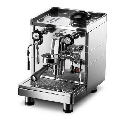
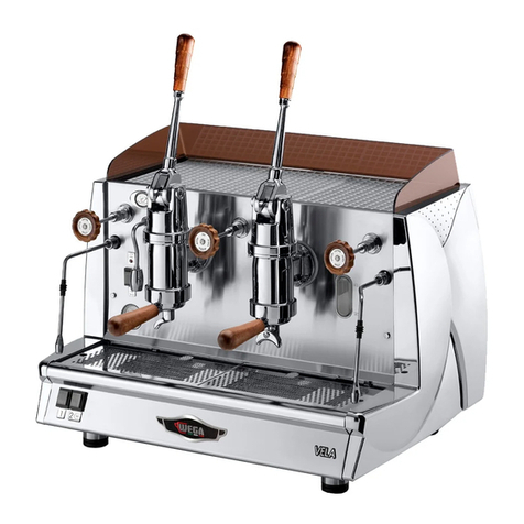
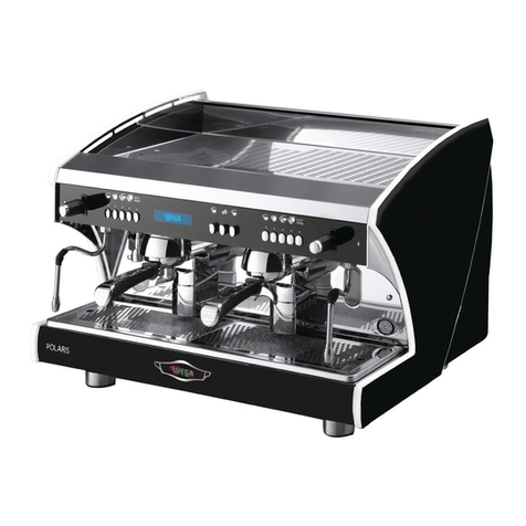
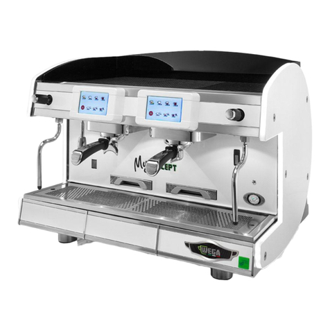
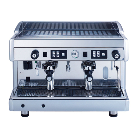
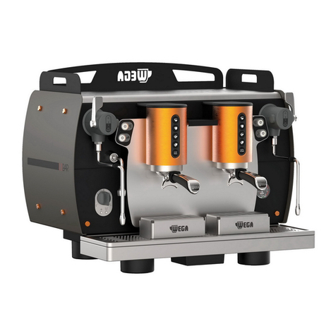
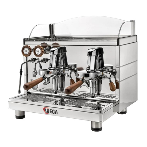
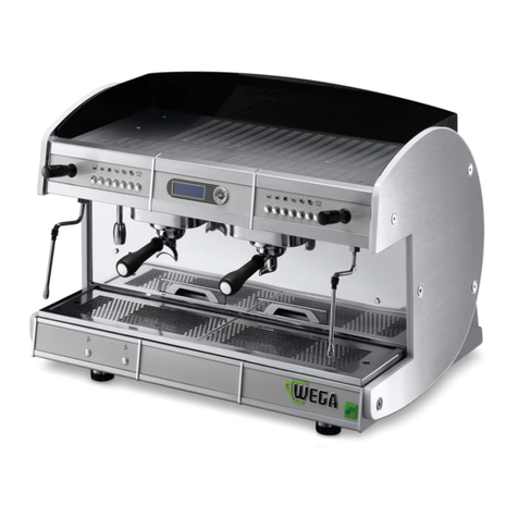
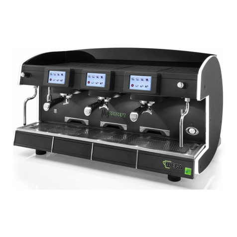
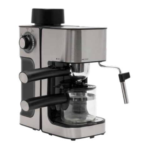
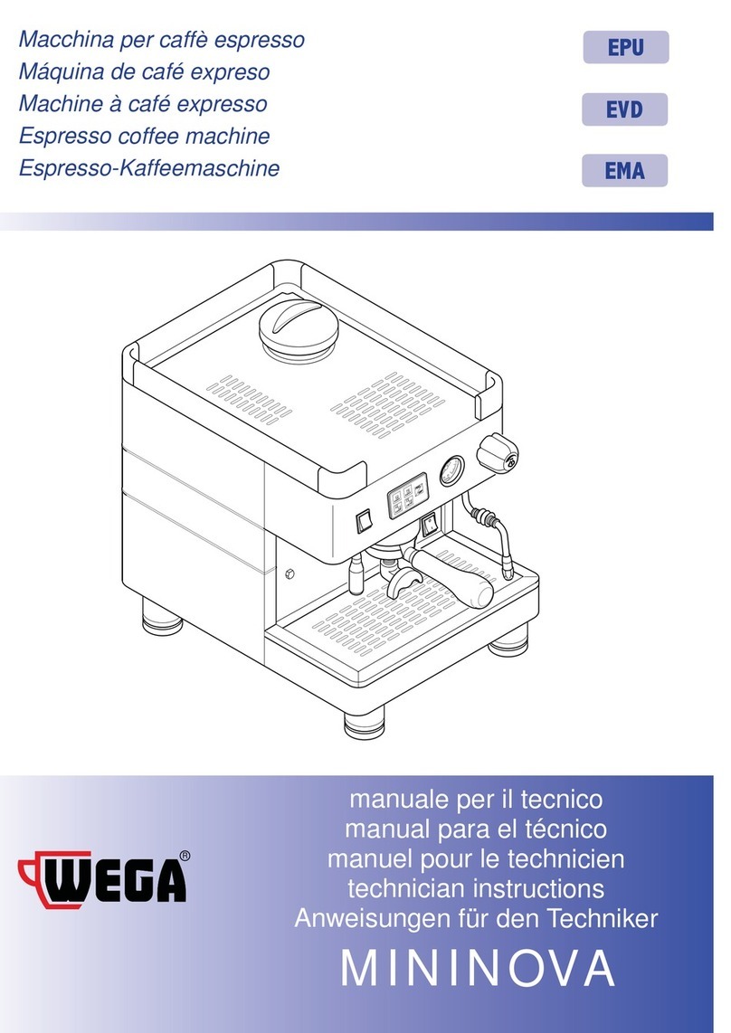
Wega ALE User manual

ALE
EMA
EPU
EVD
EN ESPRESSO COFFEE MACHINE
Use and Maintenance Manual. TECHNICIANS' instructions.

All rights reserved on contents The total or partial reproduction and the dissemination of this document’s contents is forbid-
den without the Manufacturer’s prior written authorisation. The Company logo is owned by the Manufacturer of the Machine.
IMPORTANT: Read carefully before use. Store for future reference.

TECHNICIANS' manual 3of 100
I. SAFETY PRECAUTIONS
I.I. LEVEL OF TRAINING AND
KNOWLEDGE REQUIRED OF THE
TECHNICIAN
The Technician is a specialised person that
has been specially trained and authorised
to carry out the following operations in ac-
cordance with current regulations: transport
and handling, storage, installation, commis-
sioning, maintenance, decommissioning, dis-
mantling and disposal of the machine.
The Technician must be properly trained
and informed regarding any residual risks
present during these operations and while
the machine is operating.
The Technician must be able to apply all the
good practices in compliance with food hy-
giene principles.
Any unauthorised tampering with
any parts of the machine renders
the guarantee null and void and relieves
the manufacturer of any liability should
the machine malfunction or any user ac-
cidents occur.
I.II. SAFETY PRECAUTIONS
Even though the machine is provided with
all safety devices required to eliminate pos-
sible risks for the Technician, there are still
certain residual risks.
These so-called residual risks are related to
machine parts that may pose a risk to the
Technician, if used improperly, evaluated
or deactivated incorrectly, because the pre-
scriptions contained in this Manual were cir-
cumvented.
The machine is also equipped with appropri-
ate warnings placed on residual risk areas,
which must be scrupulously observed.
Attention must be paid to the residual risks
that are present during the operations de-
scribed in the following paragraphs as they
cannot be eliminated:
Compliance with the installation and ma-
chine’s safety standards is dependent on
the use, installation, maintenance and cor-
rect operation of the machine. These fac-
tors are the responsibility of the purchaser,
Technician and Technician’s employer.
The Technician’s employer is responsible for
hiring and training personnel to correctly in-
stall, run and perform maintenance work on
the machine and its protection systems.
I.III.TRANSPORT AND HANDLING
Hand crushing hazard
Handling operations must always and ex-
clusively be performed by the Technician
and in compliance with the current health
and safety regulations.
Before starting the transport and/or han-
dling manoeuvres, check the route, dimen-
sions needed, safety distances, places suit-
able for placing the load down, and the
appropriate equipment for the operation.
Handling operations must be carried out by
at least 2 people, or with the help of special
lifting equipment.
In view of the substantial weight of the equip-
ment, exercise great caution during the han-
dling operations.
The Manufacturer is not responsible for any
injury or damage caused by clothing, lifting
equipment and personal equipment which
was not suitable for the type of intervention
that the operator had to carry out.
The packaging material must not be left
within the reach of children, since it is a po-
tential source of danger.

TECHNICIANS' manual4of 100
I.IV.INSTALLATION
Electrical hazard
High temperature hazard
Risk of explosion
It is prohibited to perform mainte-
nance on moving components
Installation operations must always and
exclusively be performed by the Technician
and in compliance with the current health
and safety regulations.
The appliance’s water supply must provide
water which is suitable for human consump-
tion, and must conform with the regulations
in force in the place of installation.
The Technician must carry out the hydraulic
connections in accordance with the hygiene
and hydraulic safety standards regarding
environmental protection which are in force
in the place of installation.
To ensure electrical safety, the appliance
must be connected to an effective earth-
ing system, and the system in which it is
installed must be equipped with a suitable
differential circuit breaker, in compliance
with the safety laws and standards.
The effectiveness of the earthing system
and functionality of the differential circuit
breaker - both of which are fundamental
for guaranteeing the appliance’s electrical
safety - are the responsibility of the person in
charge of the electrical system on which the
equipment is installed.
The manufacturer cannot be considered re-
sponsible for any damage caused by an in-
adequate electric system.
Make sure that the electric mains power is
enough to supply the energy needed for the
machine to correctly operate.
The appliance installation operations must
be carried out with the electrical mains
switched off. To make the electrical system
safe and be able to carry out operations
when the machine is not powered, the Tech-
nician must apply the rules prescribed by
current technical standards (disconnect the
power supply, avoid reclosures, check that
there is no voltage, etc.).
I.V. MAINTENANCE AND CLEANING
Electrical hazard
High temperature hazard
Risk of explosion
The only personnel authorised to
access the service area are those
who are knowledgeable about and have
practical experience using the appliance,
particularly in regards to safety and hy-
giene.
Maintenance and cleaning operations must
always and exclusively be performed by the
Technician and in compliance with the cur-
rent health and safety regulations.
The maintenance and cleaning operations
must comply with the safety regulations:
• Do not carry out maintenance work
when the machine in operation.
• Do not immerse the machine in water.
• Do not spill liquids on the machine or
use water jets when cleaning.
• Do not allow maintenance and clean-
ing operations to be carried out by
children or incompetent people.
• Do not perform maintenance and
cleaning operations other than those
described in this manual.
When cleaning, pay attention to the parts
of the machine that can become hot:
• Avoid contact with the dispensing
group, water spouts and steam nozzles.

TECHNICIANS' manual 5of 100
• Do not place your hands or other body
parts near the steam, hot water or milk
dispensing nozzle tips.
If gas is used (where applicable), take spe-
cial care with the following:
• When indoors, always provide air vents.
• Check for any gas leaks.
• Do not under any circumstances at-
tempttolightthegaswithoutrst
installing the proper injector.
• Do not start up the gas burners when
the heating unit is empty.
Only perform the maintenance and clean-
ing operations indicated in this manual.
If the problem cannot be resolved, switch off
the machine and contact the Manufacturer.
All maintenance operations must be carried
out when the power supply has been turned
off, the water mains has been closed off, and
the machine has completely cooled down.
After maintenance and/or repair work, the
components that are used must ensure
that the hygiene and safety requirements
initially provided for the appliance are still
met. These are met by only using origi-
nal spare parts. When components which
come into contact with water or food are
repaired or replaced, a washing procedure
hastobecarriedout,asifitweretherst
installation.
The Technician must inform the User
about the methods of periodic te-
sting of pressure equipment and safety de-
vices in accordance with the legislation in
force in the country of installation.
I.VI.EMERGENCY SITUATIONS
Should an emergency situation occur as a
result of a machine malfunction, adopt the
measures provided for in the emergency
plan posted in the premises and in any case,
proceed to immediately carry out the ac-
tions based on the type of problem.
SHORT CIRCUIT FIRE
In the event of a re caused by the ma-
chine’s electrical system malfunctioning,
adopt the following behaviours:
• Disconnect the machine from the
power mains via the main switch.
• Callthereandrescueservice.
• Get everyone a safe distance away
from the premises.
• ExtinguishtheamesusingaCO2re
extinguisher.
GAS LEAK
In the event of a re caused by the ma-
chine’s system malfunctioning, adopt the
following behaviours:
• Shut off the gas supply by closing the
valve upstream of the machine.
• Get everyone a safe distance away
from the premises.
• Ventilate the premises.
• Call the technician that installed the
machine.
• Ifnecessary,callthereandrescue
service.
GAS LEAK FIRE
In the event of a re caused by the ma-
chine’s gas system malfunctioning, adopt
the following behaviours:
• Shut off the gas supply by closing the
valve upstream of the machine.
• Disconnect the machine from the
power mains via the main switch.
• Callthereandrescueservice.
• Get everyone a safe distance away
from the premises.
• ExtinguishtheamesusingaCO2re
extinguisher.

TECHNICIANS' manual6of 100
General contents
1. INTRODUCTION.................................................................... 7
1.1 Guidelines for reading the Manual....................................7
1.2 Storing the Manual...................................................................7
1.3 Method for updating the Instruction Manual..............7
1.4 Recipients......................................................................................7
1.5 Glossary and Pictograms........................................................8
1.6 Guarantee.....................................................................................9
2. MACHINE IDENTIFICATION............................................ 9
2.1 Make and model designation..............................................9
2.2 General description...................................................................9
2.3 The manufacturer’s customer service..............................9
2.4 Intended use.............................................................................10
2.5 Machine diagram...................................................................10
2.6 Front command pushbutton panels..............................12
2.7 Internal components............................................................13
2.8 Data and CE marking...........................................................14
3. TRANSPORT AND HANDLING .......................................21
3.1 Safety precautions.................................................................21
3.2 PPE features ..............................................................................21
3.3 Dimensions and weight.......................................................21
3.4 Handling the packed machine .........................................21
3.5 Unpacking the machine......................................................21
4. STORAGE.................................................................................22
4.1 Overview.....................................................................................22
4.2 Storing the machine after operation.............................22
5. INSTALLATION.....................................................................22
5.1 Safety precautions.................................................................22
5.2 PPE features ..............................................................................22
5.3 Environmental conditions...................................................22
5.4 Installation and operation spaces..................................23
5.5 Support base.............................................................................23
5.6 Drilling the support base.....................................................25
5.7 Hydraulic connection............................................................26
5.8 Gasconnection(iftted)....................................................28
6. COMMISSIONING ..............................................................32
6.1 Safety precautions.................................................................32
6.2 Preparingthelterholders.................................................32
6.3 Lighting(iftted) ...................................................................32
6.4 Cupwarmer(iftted)...........................................................32
6.5 Automatic steam wand (if applicable).........................33
6.6 Turning the machine on and off......................................33
6.7 Water renewal..........................................................................34
6.8 Dispensing coffee...................................................................35
6.9 Dispensing steam...................................................................37
6.10 Dispensing hot water ...........................................................38
6.11 Dispensing cappuccinos (optional)................................39
6.12 Cup warmer...............................................................................39
6.13 Tips for a good cup of coffee..........................................40
7. MAINTENANCE AND CLEANING.................................41
7.1 Safety precautions.................................................................41
7.2 PPE features ..............................................................................41
7.3 Maintenance ............................................................................41
7.4 Waterltermaintenance....................................................44
7.5 Water softener regeneration.............................................46
7.6 Malfunctions and solutions................................................47
7.7 Cleaning operations..............................................................50
8. SPARE PARTS .........................................................................52
9. DECOMMISSIONING ........................................................52
9.1 Short period of machine inactivity.................................52
9.2 Long period of machine inactivity..................................52
10. DISASSEMBLY.......................................................................52
11. DISPOSAL ...............................................................................52
11.1 Disposal information.............................................................52
11.2 Environmental information................................................52
12. WIRING DIAGRAMS..........................................................53
12.1 ELECTRIC MAINS connection .........................................53
12.2 MACHINE Power Supply ....................................................54
12.3 ALE - EMA version..................................................................55
12.4 Single-phase U.L. - VELA EMA version...........................56
12.5 230-400V VELA EMA version............................................57
12.6 EPU version ..............................................................................58
12.7 EVD version..............................................................................59
13. HYDRAULIC DIAGRAMS..................................................80
13.1 LEVER GROUP hydraulic diagram..................................80
13.2 EMA - EPU DISPENSING GROUP .......................................
hydraulic diagram...................................................................81
13.3 EVD - DISPLAY DISPENSING GROUP hydraulic ..........
diagram.......................................................................................82
14. CREDIT-DEBIT and DEBIT-CREDIT SYSTEMS.........83
14.1 CREDIT-DEBIT system........................................................83
14.2 DEBIT - CREDIT system with direct connection ..........
to the TILL .................................................................................87
14.3 DEBIT - CREDIT SYSTEM with connection ....................
to the INTERFACE..................................................................91
TECHNICIANS' manual 7of 100
1. INTRODUCTION
Read this manual carefully. It provides important safety infor-
mation to the Technician regarding the operations indicated
in this document.
Keep this Manual in a safe place. If you lose it, you can ask the
Manufacturer for another copy.
The Manufacturer of the appliance cannot be held responsi-
ble for any damage caused due to the non-observance of the
requirements listed in this manual.
Before carrying out operations on the machine,
read the instructions contained in this publica-
tion and follow the guidelines carefully. Keep this
manual and all attached publications in an accessible and
secure place.
This document assumes that the machine is installed in a lo-
cation where the current work safety and hygiene standards
are observed.
The instructions, drawings and documentation contained in
thisManualaretechnicalandcondential.Theyarethesole
property of the Manufacturer, and may not be fully or par-
tially reproduced in any way.
The Manufacturer reserves the right to make any improve-
ments and/or modications to the product. We guarantee
thatthisManualreectsthetechnicalstateoftheappliance
at the time it was released to the market.
We encourage the Technicians to make any proposals in re-
gards to improving the product or its Manual.
1.1 Guidelines for reading the Manual
This Manual is divided into separate chapters. The chapter
order is linked to the temporal logic of the life of the machine.
Terms, abbreviations and pictograms are used to facilitate
the immediate understanding of the text.
This Manual consists of cover, index and series of chapters.
Each chapter is sequentially numbered. The page number is
shown in the footer.
Themachineidenticationdataisdisplayedonthemachine’s
nameplate and the EU declaration of Conformity, whilst the
date and revision of the Instruction Manual is provided on
the last page.
Abbreviations
Sec. = Section
Chap. = Chapter
Para. = Paragraph
P. = Page
Fig. = Figure
Tab. = Table
Units of measurement
The units of measurement are those provided by the Interna-
tional System (SI).
1.2 Storing the Manual
The Instruction Manual must be stored carefully. The manual
should be stored, handled with care with clean hands and not
placed on dirty surfaces. The Manual must be stored in an
environment protected from moisture and heat.
Do not remove, tear or arbitrarily modify any of its parts.
On the Technician's request, the manufacturer can provide
additional copies of the machine's Instruction Manual.
1.3 Method for updating the Instruction
Manual
The Manufacturer reserves the right to modify and make im-
provements to the machine without providing notice or up-
dating the Manual that has already been received.
Should the Manual become illegible or other-
wise hard to read, the Technicians must request
a new copy from the Manufacturer before car-
rying out any operations on the machine.
It is absolutely forbidden to remove or rewrite parts of
the Manual.
The instructions, drawings and documentation contained
in this manual are condential and the sole property of
the Manufacturer. They may not be reproduced in any
way, either in full, or in part without prior authorisation.
The Technician is responsible for complying with the in-
structions contained in this Manual.
Should any incident occur as a result of these recom-
mendations being used incorrectly, the Manufacturer
declines any liability.
This manual is also available on the manufacturer's web-
site shown on the cover of the manual.
1.4 Recipients
This Manual is intended for the Technician who is responsible
for carrying out the following operations on the machine:
• Transport and handling;
• Storage;
• Installation;
• Commissioning;
• Maintenance;
• Cleaning;
• Spare part replacement;
• Emergency operations and faults;
• Decommissioning;
• Disassembly;
• Disposal (refer to the retailer if not directly responsible).

TECHNICIANS' manual8of 100
RECIPIENT QUALIFICATIONS
The machine is intended for a professional non-generalised
use, therefore the Technician must:
• Have attended the training courses organised by the Man-
ufacturer relating to the type of machine;
• be aged 18 and over;
• bephysicallyandmentallyttousethemachine;
• be able to understand and interpret the Instruction Man-
ual and the safety requirements;
• know the safety procedures and how they are imple-
mented;
• be able to use the machine;
• haveunderstoodtheproceduresofuseasdenedbythe
machine's manufacturer.
1.5 Glossary and Pictograms
This paragraph lists uncommon terms or terms whose mean-
ings are different than those most commonly used.
Abbreviations are explained below, as well as the meaning
ofpictogramsdescribingtheoperator'squalicationandthe
machine status; they are used to quickly and uniquely pro-
vide the information needed to correctly and safely use the
machine.
1.5.1 Glossary
User
The person in charge of operating the machine and performing
the routine cleaning operations indicated in this manual.
Technician
A specialised person who has been specially trained and au-
thorised to carry out the following operations in accordance
with current regulations: transport and handling, storage, in-
stallation, commissioning, maintenance, decommissioning,
dismantling and disposal of the machine.
Danger
A potential source of injury or damage to health.
Dangerous area
Any area in the vicinity of the machine where the presence
of a person constitutes a risk to the safety and health of that
person.
Risk
Combination of the probability and severity of an injury or
damage to health that can arise in a hazardous situation.
Guard
Machine component used specically to provide protection
by means of a physical barrier.
Personal protective equipment (PPE)
Clothing or equipment worn by someone to protect their
health or safety.
Intended use
The use of the machine in accordance with the information
provided in the instructions for use.
Machine status
The machine status includes the mode of operation and the
condition of the machine's safety devices.
Residual risk
Risks that remain despite adopting the protective measures
integrated into the machine's design and despite the guards
and complementary protective measures that have been
adopted.
Safety component:
• Designed to perform a safety function.
• whose failure and/or malfunction endangers the safety of
persons.
1.5.2 Pictograms
Descriptions preceded by these symbols contain very im-
portant information/requirements, particularly in regards to
safety. Failure to comply with these may result in:
• A safety risk for those operating the machine.
• User injury, including serious injury (in some cases even
death).
• The guarantee being rendered null and void.
• The Manufacturer waiving liability.
GENERAL DANGER symbol used when there is a
risk of permanent serious injury that would re-
quire hospitalisation, or in extreme cases, even
cause death.
ELECTRICAL HAZARD symbol used when there
is a risk of permanent serious injury that would
require hospitalisation, or in extreme cases,
even cause death.
HIGH TEMPERATURE HAZARD symbol used
when there is a risk of permanent serious injury
that would require hospitalisation, or in ex-
treme cases, even cause death.
HAND CRUSHING RISK symbol used when
there is a risk of permanent serious injury that
would require hospitalisation, or in extreme
cases, even cause death.
EXPLOSION RISK symbol used when there is a
risk of permanent serious injury that would re-
quire hospitalisation, or in extreme cases, even
cause death.

TECHNICIANS' manual 9of 100
CAUTION symbol used when there is a risk of
minor injury that could require medical atten-
tion.
WARNING symbol used when there is a risk of
minor injury that could be treated with rst-aid
or similar measures.
NOTE symbol used to provide important infor-
mation about the topic.
It is prohibited to perform maintenance on mov-
ing components as there is a risk of permanent
serious injury that could require hospitalisation.
Mandatory symbol indicating that safety gloves
must be worn; used when there is a risk of perma-
nent serious injury that would require hospitali-
sation.
Mandatory symbol indicating that eye protec-
tion must be used when there is a risk of perma-
nent serious injury that would require hospitali-
sation.
Mandatory symbol indicating that safety shoes
must be used when there is a risk of permanent
serious injury that would require hospitalisa-
tion.
Mandatory symbol indicating that the documenta-
tion must be read; used to make the Technician aware
of the importance of this action for their safety.
1.6 Guarantee
All of the machine's components are covered by a 12-month
guarantee, except for electrical and electronic components
and parts prone to wear and tear.
If any work is carried out on the machine electronics when
the machine is still live, any guarantee will automatically be
invalidated.
2. MACHINE IDENTIFICATION
2.1 Make and model designation
The machine and model ID information is found on the ma-
chine's NAMEPLATE and in the provided EU DECLARATION
OF CONFORMITY.
2.2 General description
The machine described in this Manual consists of mechani-
cal, electrical, and electronic components which, when used
together, produce milk, coffee and water-based beverages.
This product is manufactured in compliance with the EU Di-
rectives, Regulations and Standards indicated in the EU DEC-
LARATION OF CONFORMITY provided with the machine.
2.3 The manufacturer’s customer
service
WEGA MACCHINE PER CAFFÈ S.R.L.
Via Condotti Bardini, 1
31058 SUSEGANA (TV) - ITALY
Tel. +39.0438.1799700 - Fax +39.0438.1884890

TECHNICIANS' manual10 of 100
2.4 Intended use
The espresso coffee machine has been designed to profes-
sionally prepare hot beverages such as tea, cappuccinos and
weak, strong and espresso coffee, etc. The appliance is not
intended for domestic use, it is intended for professional pur-
poses only.
The machine can be used under all the conditions set forth,
contained or described in this document; any other condi-
tions must be considered dangerous. The machine must be
installedinaplacewhereitsaccessisrestrictedtoqualied
personnel only who have received suitable training (coffee
shops, restaurants, etc.).
Permitted uses
All uses compatible with the technical features, operations
and applications described in this document which do not
endanger the safety of users or can cause damage to the ma-
chine or its surrounding environment.
All uses not specically mentioned in this Man-
ual are prohibited and must be expressly autho-
rised by the Manufacturer.
Intended uses
The machine has been designed exclusively for professional
use.Theuseofproducts/materialsotherthanthosespecied
by the Manufacturer, which can cause damage to the ma-
chine and be dangerous for the operator and/or those in close
proximity to the Machine, is considered incorrect or improper.
Contraindications of use
The machine must not be used:
• for uses other than those indicated in this paragraph or for
uses that differ from or are not mentioned in this Manual.
• with materials other than those listed in this Manual.
• with safety devices that have been disabled or are not
working.
Incorrect use of the machine
The type of application and performance that this machine
has been designed for, requires a number of operations and
procedures that cannot be changed, unless previously agreed
with the Manufacturer. All permitted behaviours are indicated
in this document; any operation not listed and described
herein is to be considered improper and therefore, hazardous.
Improper use
The only permitted uses are described in the Manual; any
other use is considered improper and therefore, hazardous.
General safety features
The Technician must be aware of accident risks, safety devices
and the general safety rules set forth in EU directives and by
the legislation of the country where the machine is installed.
The Technician must know how all the machine's devices
work. They must also have fully read and understood this
Manual. Maintenance work must be performed by the Techni-
cian after the machine has been properly prepared. The tam-
pering or unauthorised replacement of one or more machine
components, the use of accessories which modify its use and
the use of materials other than those recommended in this
Manual, can cause accidents.
2.5 Machine diagram
1. Cup warmer shelf
2. Group lever
3. Heating unit water level window (in some versions, the
level window is replaced by a green indicator light)
4. Pressure gauge
5. Steam knob
6. Scald protection
7. Steam nozzle
8. 2-cuplterholder
9. Adjustable foot
10. Hot water nozzle
11. Gas burner inspection window (optional)
12. 1-cuplterholder
13. Gas safety (optional)
14. Gas adjustment (optional)
15. Gas ignition button (optional)
16. Cup holder grille
17. Power switch
18. Machine on indicator light
19. Hot water knob/button
20. Manual dispensing switch
21. Pushbutton panel
22. Heatingunitmanualwater-llingbutton
23. Cup warmer button
24. Blindlter
25. Presser
26. Cleaning brush
24
25
26
1 2
0
1 2
0
1 2
0
ALE version
EPU version
EVD version
1
2
3
6
2
6
6
3
5
5
5
17
3
7
7
7
9
9
16
16
16
9
4
419 20
20
21
812
12
12
11 22
22
22
14
14
14 11
111315
15
15
8
8
13
13
17
17
1
7
7
6
6
6
10
18
18
19
19
18
10
7
5
5
5
1
4 10

TECHNICIANS' manual 11 of 100
General safety features
The Technician must be aware of accident risks, safety devices
and the general safety rules set forth in EU directives and by
the legislation of the country where the machine is installed.
The Technician must know how all the machine's devices
work. They must also have fully read and understood this
Manual. Maintenance work must be performed by the Techni-
cian after the machine has been properly prepared. The tam-
pering or unauthorised replacement of one or more machine
components, the use of accessories which modify its use and
the use of materials other than those recommended in this
Manual, can cause accidents.
2.5 Machine diagram
1. Cup warmer shelf
2. Group lever
3. Heating unit water level window (in some versions, the
level window is replaced by a green indicator light)
4. Pressure gauge
5. Steam knob
6. Scald protection
7. Steam nozzle
8. 2-cuplterholder
9. Adjustable foot
10. Hot water nozzle
11. Gas burner inspection window (optional)
12. 1-cuplterholder
13. Gas safety (optional)
14. Gas adjustment (optional)
15. Gas ignition button (optional)
16. Cup holder grille
17. Power switch
18. Machine on indicator light
19. Hot water knob/button
20. Manual dispensing switch
21. Pushbutton panel
22. Heatingunitmanualwater-llingbutton
23. Cup warmer button
24. Blindlter
25. Presser
26. Cleaning brush
24
25
26
1 2
0
1 2
0
1 2
0
ALE version
EPU version
EVD version
1
2
3
6
2
6
6
3
5
5
5
17
3
7
7
7
9
9
16
16
16
9
4
419 20
20
21
812
12
12
11 22
22
22
14
14
14 11
111315
15
15
8
8
13
13
17
17
1
7
7
6
6
6
10
18
18
19
19
18
10
7
5
5
5
1
4 10

TECHNICIANS' manual12 of 100
2.6 Front command pushbutton panels
1 espresso
1 large
coffee
2 espressos
2 large
coffees
Stop
Programming
2
espressos
1
espresso
2 large
coffees
1 large
coffee
1 espresso 1 espresso
2 espressos 2 espressos
Hot water
1 large
coffee
1 large
coffee
2 large
coffees 2 large
coffees
Stop
Programming
Stop
Programming

TECHNICIANS' manual 13 of 100
2.7 Internal components
1. Heating unit
2. Dispensing group
3. Internal motor pump (*)
4. Heating unit/motor pump pressure gauge
5. Heating unit level-check window
6. Internal pump water attachment connection (*)
7. Manual water pump
8. External pump water attachment connection
9. Drain tray
10. Volumetric dosing device (EVD)
11. Machine power switch
12. Gas system (*)
13. Electric heating element
14. Pressure switch
15. Transformer
16. Work surface LED light
1 2 3
4
5
6
7
8
9101112
13
14
17. Heating unit thermostat
18. Heating unit pressure switch
(*) Optional device

TECHNICIANS' manual14 of 100
2.8 Data and marking
The machine’s general technical data is provided in the fol-
lowing table:
TECHNICAL DATA TABLE 1GR COMPR. 2GR 3GR 4GR
120 V
Power
2200-2330 W 2900 W 2330-2930 W --- ---
220-240 V
2700-3300 W 2900-3100 W 2800-4850 W 4850-6300 W 5000-7900 W
380-415 V
Frequency 50-60 Hz 50-60 Hz 50-60 Hz 50-60 Hz 50-60 Hz
Heating unit 5,5-6 l 7 l 9,5-10,6 l 15,5-17,2 l 23-23,8 l
Safety valve calibration 0,19 MPa (1,9 bar) +/- 0,015 MPa
Heating unit operating pressure 0.08 - 0.14 MPa (0.8 - 1.4 bar)
Mains water pressure 0.15 - 0.6 MPa max. (1.5 - 6 bar max.)
Coffee dispensing pressure 0.8 - 0.9 MPa (8 - 9 bar)
Working environment temperature 5 - 35°C 95° MAX. R.H.
Sound pressure level < 70 dB
The nameplate is afxed
under the drain tray
In compliance with directive 2006/42/CE, the machine is
marked with the CE code with which the manufacturer de-
clares under his responsibility that the machine is safe for
persons and things.
Alternativemarkingscanbeafxedaccordingtothetarget
markets, provided they comply with current product regula-
tions.
The nameplate which provides the appropriate markings,
identicationdataandspecictechnicaldata,isafxedun-
der the drain tray.
An example of a nameplate is provided below.
When contacting the Manufacturer, always provide the fol-
lowing information:
• S/N - machine serial number.
• Mod. - machine model.
• Y - year of manufacture.
The appliance data can also be found on the label located on
the machine's packaging.
It is forbidden to remove or modify the name-
plate. Should it deteriorate or become illegible,
contact the Manufacturer.
To correctly connect the machine to the electric
mains, refer to Chap. "12. WIRING DIAGRAMS" on
page 53.
Via
C.
B
a
r
d
i
n
i,
1
S
U
S
E
GANA
(
T
V)
-
I
T
ALY
Tel. +39.0438.1799700 - Fax +39.0438.1884890
MADE IN IT
A
LY
W
S/N:
Mod
.
H
z
Y
V
WEG
A
M
A
C
C
H
I
N
E
P
E
R
CA
F
F
È
S
.
r
.
l
.
TRADEMARK

TECHNICIANS' manual 15 of 100
2.8.1 Heating unit
The heating unit is made of copper sheet metal (1). The heat
exchangers are assembled onto this unit and are in turn con-
nected to the dispensing group. The water used for dispensing
coffee is taken directly from the heat exchanger. During the
dispensing process, cold water is sent inside the exchanger
by means of the motor pump. Cold water and the pre-exist-
ing hot water are mixed together inside the heat exchanger,
in order to obtain the optimal water temperature for coffee
infusion.
2
1
Electric heating
The heating unit is electrically heated by an electric heating
element immersed in the water (2).
Gas heating
Gasheatingisobtainedbyfeedingtheburneramewhichis
located under the heating unit.
Electric + gas heating
In machines equipped with both systems, it is possible to
combine the two heating types.
2.8.2 Overow device
The cover installed on the pressure relief valve makes it possi-
ble to collect any water and steam which may leak from the
heating unit due to a malfunction and channel it to the drain
tray, via a special hose.
2.8.3 Pressure relief safety valve
The pressure relief safety valve has a calibration
of 0.19 MPa (1.9 bar) in order to ensure that the
pressure in the steam heating unit does not exceed
0.21 MPa (2.1 bar). Should a fault occur, the capac-
ity of the valve is such as to be able to eliminate all
the excess pressure in the heating unit.
The safety valve should be checked regularly as
indicated in Chap. "7. MAINTENANCE AND
CLEANING" on page 41.
Two safety valves are installed on all machines
with 4 groups.
2.8.4 Expansion valve + check valve
This is a valve consisting of an expansion valve and a check
valve.
• Expansion valve (A):
the cold water sent from the pump to the heat exchangers
is heated. This heating causes an increase in the volume
of water. To limit pressure increases in
the hydraulic circuit, the valve limits
the maximum internal pressure of the
circuit to 1.2 MPa (12 bar).
• Check valve (B):
its function is to prevent the water
back-owingintothehydrauliccircuit
exchangers.
2.8.5 Negative pressure valve
The purpose of the negative pressure valve is to pre-
vent liquids from back-owing through the steam
nozzle when they are being heated. Furthermore, the
excess air inside the heating unit is removed during
the machine's heating phase.
2.8.6 Pressure switch
The pressure switch makes it possible
to control the heating unit pressure by
activating or bypassing the heating
element in the heating unit. Any pres-
sure switch calibration can be carried
out with the machine in operation by
turning the screw (6) located on the
body of the component.
A
B
6

TECHNICIANS' manual16 of 100
2.8.7 LEVER group
The group lever uses the heating unit pressure and water. This
system does not require heat exchangers.
When the lever (1) is lowered, the spring (2) inside the group
is compressed: the piston (3) raises, allowing the water to en-
ter the pre-infusion jacket.
When the lever is released, the piston compresses the water
at 8-10 bar, allowing the espresso coffee to be dispensed.
The check ball valve (4)preventsthewaterfromowingback
into the heating unit (5).
1
45
2
3
PHASE 1
Lowering the
lever
PHASE 2
Pre-infusion for
3-5 seconds
PHASE 3
The lever releases
and coee is dis-
pensed.
2.8.8 LEVER group
A system similar to the one shown for the Dispensing Group is
used for the lever group; see para. XX.
In this case the dispensing is controlled by a spring system.
The opening and closing of the valve for the water ow is
done by pressing a lever on the side of the group that, in turn,
moves a camme within the group, allowing or not allowing
the passage of water.

TECHNICIANS' manual 17 of 100
2.8.9 DISPENSING group
In this system, the dispensing group (1) is heated by a ther-
mosiphonic circuit (2) connected to the heat exchanger (3).
The same water is used for the coffee dispensing, thus ensur-
ing the same temperature for all coffee servings:
• The solenoid valve and the pump are activated in order to
send cold water to the exchanger (3) through the injector
(4).
• The heating unit water is carried from the exchanger (3)
to the group (4) for dispensing.
• the pump allows the increase of the pressure of the water
owupto8-9barfordispensing.
The injector (4)andow reducer(5) are important compo-
nents for the dispensing group’s operation.
To increase the coffee extraction temperature, remove the
owreducer(5) or replace it with one that has a bigger di-
ameter. To decrease the temperature, replace it with one that
has a smaller diameter.
Water
inlet
Dispensing
coee
DISPENSING IN PROGRESS
5
3
4
2
1
3
IDLE
2.8.10 Safety thermostat
The thermostat prevents any damage occurring to the elec-
trical heating element if there is no water in the heating unit.
The thermostat bulb (7) is located inside a sheath (8) in the
middle of the heating elements. The thermostat contacts (9)
are connected to the electric heating element (10). If the
electricheatingelementisexposedduetoafailuretollthe
heating unit with water, the temperature of the heating el-
ement increases dramatically. At this point, the thermostat
cuts the power supply to the heating element in order to pre-
vent damage occurring.
10
911
7
8
To reset the thermostat, press the centre button
(11). However, before starting the machine up
again, identify what prevented the water from
being fed into the heating unit.
2.8.11 Motor pump
This component feeds the machine
by increasing the water pressure to
0.8-0.9 MPa (8-9 bar) in order to dis-
pense coffee and automatically ll
the heating unit.
2.8.12 Electronic control unit
The electronic control unit is installed on the EVD versions.
Its purpose is to electronically control the cof-
fee dose via the water owing through the
dosing device and to check that the heating
unitisbeinglledwithwater.
Some versions of the control unit are set up
to be connected to the dispensing account-
ingsystemsbymeansofaspecicinterface
device.

TECHNICIANS' manual18 of 100
2.8.13 Automatic Water Entry
The Automatic Water Entry system is designed to check the
water level in the heating unit. It consists of:
• A probe inserted into the heating unit (1) consisting of a
stainless steel rod.
• The standard control unit (2) on EVD versions and the
electronic level regulator on the other versions (3).
• A hydraulic circuit with a solenoid valve controlled by the
regulator.
The electronic control unit controls the level of water in the
heating unit. When the level of water in the heating unit
drops, the contact with the probe is interrupted. The control
unit sends an impulse to the inlet solenoid valve and the mo-
tor pump, which are then activated until the normal level of
water in the heating unit has been restored.
To avoid any ooding caused by machine malfunctions or
water leaks in the circuit, the electronic control unit has a
“Timeout”featurewhichcutsofftheautomaticwaterlling
function after a certain time (2 minutes). The LED (4) located
on the front of the machine body comes on to indicate acti-
vation of this system. When installing machines with three
orfour groups,theinitialwaterllingtimemayexceedthe
established timeout limit. Should this occur, simply turn the
machine off and then back on to restore normal operating
conditions.
1
2
4
3
2.8.14 Volumetric dosing
The volumetric dosing device that is installed on the EVD ver-
sions, measures the quantity of water sent to the group in
order to dispense coffee.
The dispenser generates elec-
trical impulses which are sent
to the electronic control unit.
These impulses are read by
the control unit and counted
while the dose is being pro-
grammed.
TheashingLEDlight(4) indi-
cates that the electrical impulse has been sent from the dos-
ing device to the control unit.
2.8.15 Electronic pushbutton panels
The electronic pushbutton panels on the EVD versions allow
the coffee doses to be selected and programmed. They are
connected to the electronic control unit.
To use and programme these, please consult the user manual.
2.8.16 Cup warmer
The cup warmer device warms the cups before they are used.
In some versions it is possible to adjust the temperature by
following the instructions on the user manual.
4

TECHNICIANS' manual 19 of 100
2.8.17 Hot water spout
The hot water spout is connected to a heating unit suction
hose. Depending on the model, hot water can be dispensed
in two ways:
• Manually: by turning the adjustment knob on the front of
the machine.
• Automatically: by selecting a button connected to a sole-
noid valve.
2.8.18 Steam nozzle
The steam nozzle is connected to the top of the heating unit.
Depending on the model, steam can be supplied in two ways:
• Rotary knob: by turning the adjustment knob on the front
of the machine.
• Lever knob: the steam is supplied through the horizontal
or vertical movement of the knob.
OFF
Automatic
return
Automatic
return
Stop
Stop
2.8.19 Cappuccino maker (optional)
The cappuccino maker is installed on a steam nozzle. This de-
vice can both heat and froth the milk.
To adjust and clean the cappuccino maker, follow the instruc-
tions in the user manual.
2.8.20 Water lter
In the mains water, non-soluble salts are
present which cause limestone to form in
the heating unit and other parts of the
machine.
Drinking water can also contain heavy
metals and substances, such as chlorine
which are harmful to health.
The lter makes it possible to eliminate
or substantially reduce the presence of
these mineral salts.
Thecartridgecontainedinthewaterlter
must be replaced at the frequency speci-
edbythemanufacturer.
To use and maintain the water lter, follow the
instructions provided in para. "7.4 Water lter
maintenance" on page 44
2.8.21 Water softener
The resin softener can be used as an alternative to the water
lter.
This component has the property of retaining the calcium
contained in the water. For this reason, the
resins become saturated after a certain pe-
riod and must be regenerated with coarse
kitchen salt (NaCl, sodium chloride) or spe-
cial water softening salt. It is very important
to regenerate the softener within the estab-
lished times. However, in locations where
the water is very hard, it will be need to be
regenerated more frequently. The same rule
can be applied to locations where there is
a large consumption of hot water (for tea,
etc.).
To use and regenerate the water softener, fol-
low the instructions provided in para. "7.5 Wa-
ter softener regeneration" on page 46.

TECHNICIANS' manual20 of 100
2.8.22 Automatic steam wand (optional)
The “Automatic steam wand” system - tted on some ver-
sions with a display - enables milk to be automatically frothed
at the programmed temperature. The operating principle of
the automatic steam wand is listed below:
• Pressthespecicbutton(1), located on the left side of the
machine’s base.
• The solenoid valve opens (2) which consequently allows
thesteamtoowfromtheheatingunittotheautomatic
steam wand nozzle.
• The system simultaneously activates the air suction pump
(6) which is controlled by the control unit (3) and pow-
ered by the transformer (8). The milk froth can be adjusted
by changing the amount of air intake when opening the
valve (5).
• After the air has passed through the non-return valve (4),
it mixes with the steam in the mixing interface (11).
• Steam comes out of the nozzle (9).
• The probe (10) that is connected to the machine’s elec-
tronic control unit, detects the temperature of the milk
while it is being heated.
• Once the set milk temperature has been reached, the elec-
tronic system stops the air and steam from being dis-
pensed.
2
910
3
11
42
6
8
7
1
To adjust the milk temperature and froth, see
para. 6.5.
This manual suits for next models
3
Table of contents
Other Wega Coffee Maker manuals

Wega
Wega MININIVA CLASSIC DUO User manual

Wega
Wega Mininova User guide

Wega
Wega Espresso Coffee Machine User manual

Wega
Wega LB 4200 CAFFE'-CAFFE' User manual

Wega
Wega MyConcept EVDP 2GR User manual

Wega
Wega Mininova User manual

Wega
Wega Concept User manual

Wega
Wega WEGACONCEPT Series User manual

Wega
Wega Atlas 2010 User guide

Wega
Wega LB 4100 User manual

Wega
Wega LB 4712 Operating instructions

Wega
Wega EMA User manual

Wega
Wega URBAN EVDP User manual

Wega
Wega Mininova Classic EMA 2GR User manual

Wega
Wega Wegaconcept User manual

Wega
Wega WBAR EVD User manual

Wega
Wega WBAR EVD User manual

Wega
Wega URBAN EVDP User manual

Wega
Wega Mininova User manual

Wega
Wega Mininova User manual