WeldKing Pulsewave200 User manual

P
S
Arc Weldi
n
Machi
n
Where
Date o
f
PUL
S
P
ULSED TIG (
G
S
TICK (SMAW
)
n
g Power Sou
r
n
e Numbe
Purchas
e
f
purchas
e
S
EWAV
E
G
TAW)
)
r
ce
r:
_
e
:
_
e
d:
_
E
200
_
_______
_
_
_______
_
_
_______
_
_
_______
_
_
_______
_
_
_______
_
_
_______
_
_
_______
_
_
_______
_
_
_______
_
_
_______
_
_
_______
_
_
_
_
All manuals and user guides at all-guides.com
all-guides.com

Table of Contents
SECTION 1 SAFETY PRECAUTIONS.............................................................................................. 1
SECTION 1 CONSIGNES DE SÉCURITÉ .............................................................................................1
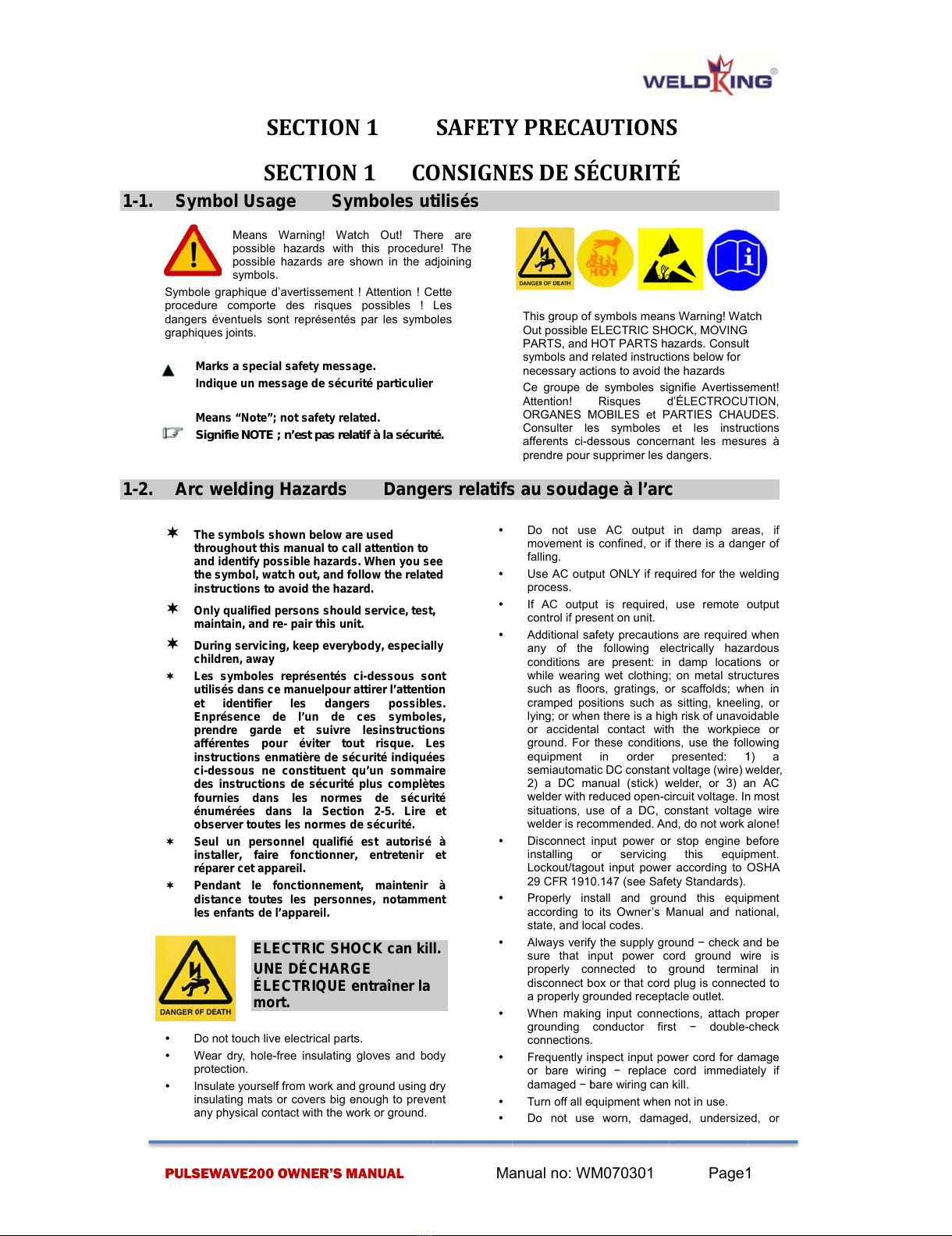
1-1. Symbol Usage Symboles utilisés................................................................1
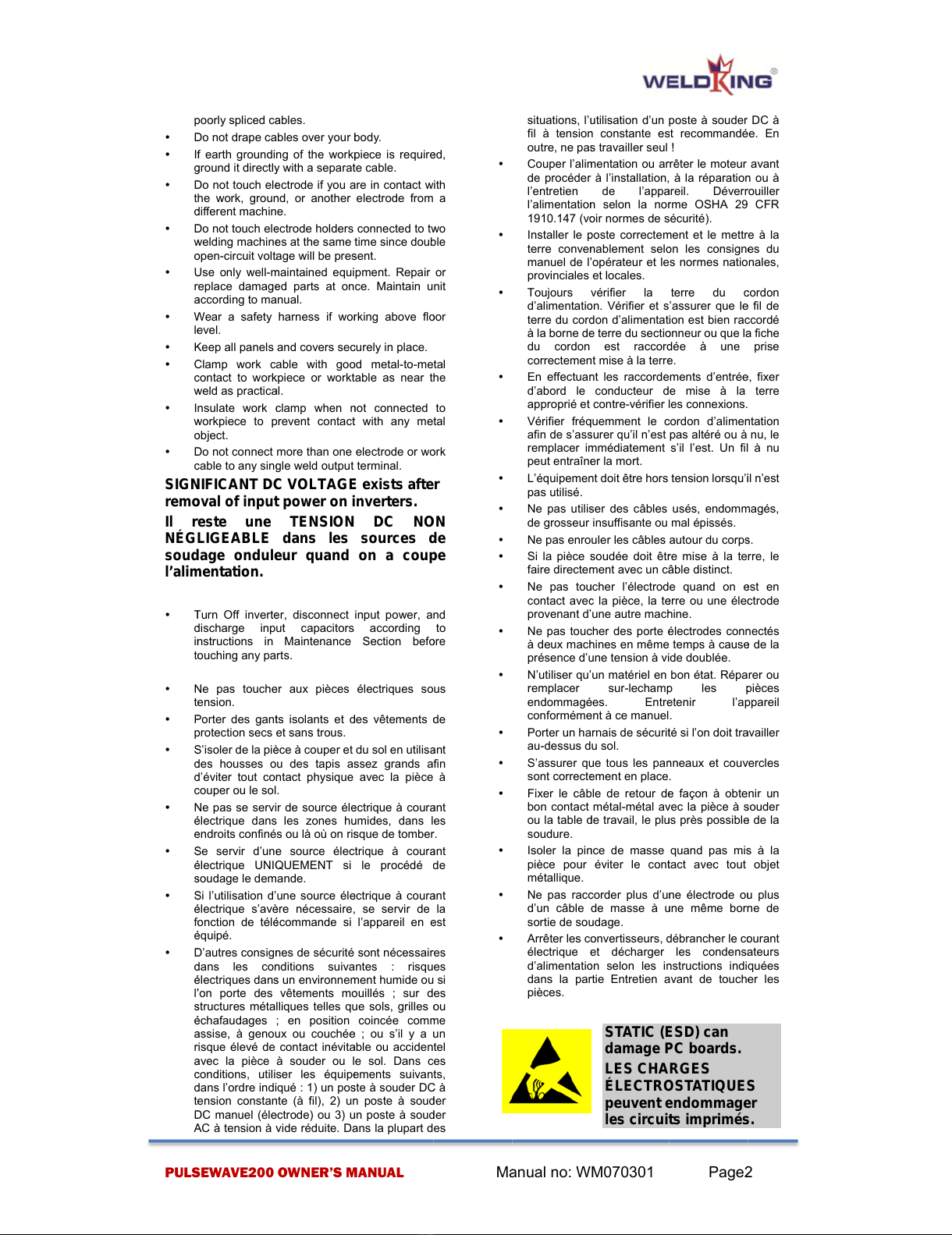
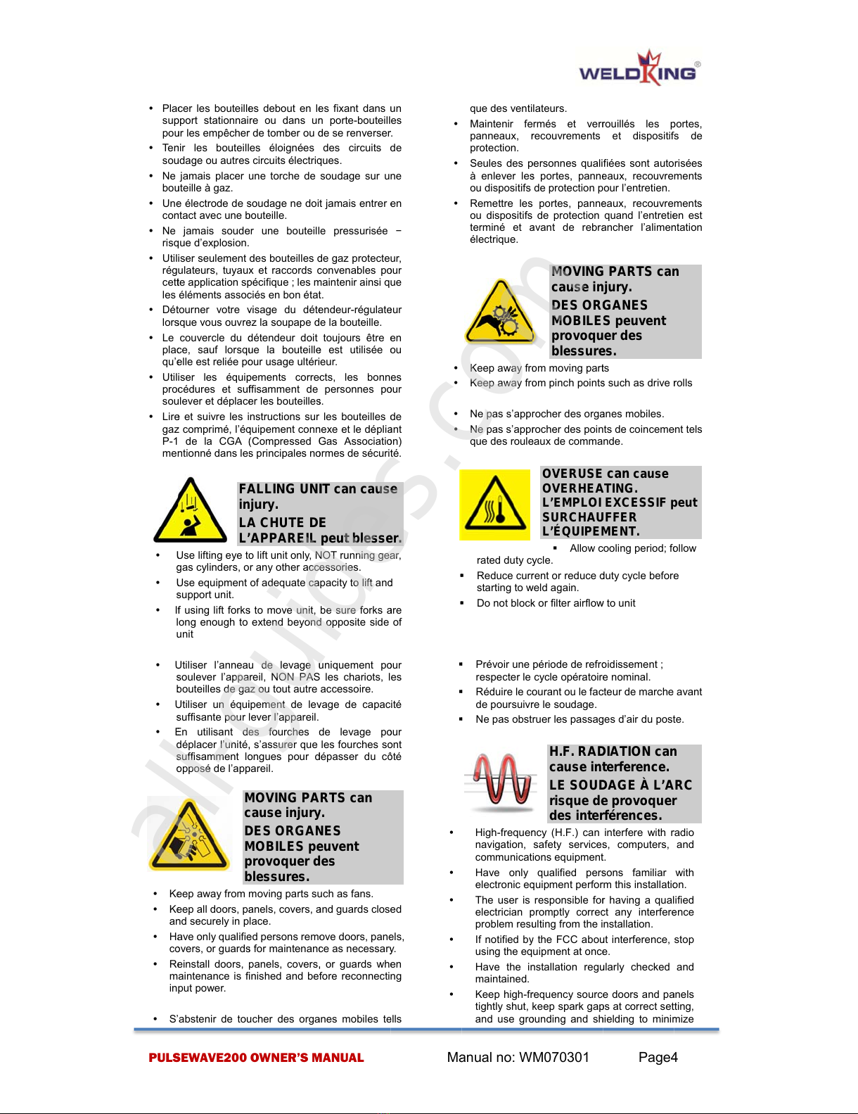
1-2. Arc welding Hazards Dangers relatifs au soudage à l’arc..................1
1-3. Safety Standards Normes de sécurité...........................................................6
1-4. EMF Information EMF Information ..............................................................6
SECTION 2 PACKING LIST............................................................................................................... 7
SECTION 3 INSTALLATIONS........................................................................................................... 8
3-1. Welding power source specifications...........................................................8
3-2. TIG torch specifications....................................................................................9
3-3. Process/Polarity Table.......................................................................................9
3-4. TIG(AC/DC) welding connection diagram ..................................................10
3-5. General installation procedure for TIG welding........................................ 11
3-6. STICK welding connection diagram ............................................................12
3-7. General installation procedure for STICK welding ..................................13
3-8. Electric service guide......................................................................................13
3-9. Extension Welding Cable Selection Chart .................................................14
SECTION 4 OPERATION .................................................................................................................... 15
4-1. Panel layout and description.........................................................................15
4-2. Parameter memory setting.............................................................................22
4-3. Parameter lockout ............................................................................................22
4-4. Short circuit protection while welding........................................................22
4-5. Operate with remote current control device connected.........................22
4-6. Operation(TIG)...................................................................................................23
4-7. Operation(STICK)..............................................................................................23
4-8. Welding Parameter selection chart..............................................................24
SECTION 5 TROUBLE SHOOTING................................................................................................... 26
5-1. General trouble shooting................................................................................26
5-2. TIG/STICK welding trouble shooting...........................................................29
SECTION 6 MAINTENANCE ............................................................................................................ 33
6-1. Maintenance.......................................................................................................33
6-2. Safety precaution..............................................................................................33
SECTION 7 PARTS LIST................................................................................................................. 36
7-1. Power Source.....................................................................................................36
7-2. TIG torch .............................................................................................................40
SECTION 8 ELECTRIC DIAGRAM................................................................................................ 45
SECTION 9 WARRANTY POLICY ................................................................................................ 47
SECTION 10 AUTHORIZED SERVICE CENTER.......................................................................... 48
All manuals and user guides at all-guides.com

PUL
S
1-1. Sy
m
Symb
o
proce
d
dange
graphi
M
I
M
S
1-2. Ar
c
T
t
a
t
i
O
m
D
c
L
u
e
E
p
a
i
c
d
f
é
o
S
i
r
P
d
l
e
y
D
y
W
p
yI
i
n
a
S
EWAVE200
S
S
mbol Usa
Means
possible
possible
symbols
o
le graphique
d
d
ure comporte
rs éventuels s
o
ques joints.
M
arks a speci
a
I
ndique un me
s
M
eans “Note”;
S
ignifie NOTE
c
welding
T
he symbols s
h
t
hroughout thi
s
a
nd identify p
o
t
he symbol, w
a
nstructions to
O
nly qualified
p
m
aintain, and
r
D
uring servici
n
c
hildren, awa
y
L
es symboles
u
tilisés dans c
e
e
t identifier
E
nprésence
d
p
rendre gard
e
a
fférentes po
nstructions e
n
c
i-dessous ne
d
es instructio
n
f
ournies dan
s
é
numérées d
a
o
bserver toute
s
S
eul un pers
o
nstaller, fair
e
r
éparer cet ap
p
P
endant le
f
d
istance tout
e
e
s enfants de
l
EL
E
UN
E
ÉL
E
mo
r
D
o not touch liv
e
W
ear dry, hole
-
p
rotection.
nsulate yoursel
f
n
sulating mats
a
ny physical co
n
OWNER’S
M
S
ECTIO
N
ECTIO
N
ge Sy
m
Warning! Wa
t
hazards with
hazards are
s
.
d
’avertissement
des risques
o
nt représenté
s
a
l safety mess
a
s
sage de sécu
not safety rel
a
; n’est pas rel
a
Hazards
h
own below a
r
s
manual to ca
o
ssible hazard
s
a
tch out, and f
o
avoid the haz
a
p
ersons shoul
d
r
e- pair this un
i
n
g, keep every
b
représentés
c
e
manuelpour
a
les dang
e
d
e l’un de
e
et suivre
ur éviter to
u
n
matière de sé
constituent
q
n
s de sécurité
s
les norm
e
a
ns la Secti
o
s
les normes
d
o
nnel qualifié
e
fonctionner
p
areil.
f
onctionneme
n
e
s les person
n
l
’appareil.
E
CTRIC SH
O
E
DÉCHAR
G
E
CTRIQUE
e
r
t.
e
electrical part
s
free insulating
f
from work an
d
or covers big
e
n
tact with the w
o
M
ANUAL
N
1
N
1 C
O
m
boles u
t
t
ch Out! The
this procedu
r
s
hown in the a
d
! Attention ! C
e
possibles !
s
par les symb
o
a
ge.
rité particulier
a
ted.
a
tif à la sécuri
t
Dang
e
r
e used
ll attention to
s
. When you s
e
o
llow the relat
e
a
rd.
d
service, test
,
i
t.
b
ody, especial
c
i-dessous s
o
a
ttirer l’attenti
o
e
rs possibl
e
ces symbol
e
lesinstructio
n
u
t risque. L
e
curité indiqué
e
q
u’un somma
i
plus complèt
e
e
s de sécur
i
o
n 2-5. Lire
d
e sécurité.
est autorisé
, entretenir
n
t, maintenir
n
es, notamm
e
O
CK can kil
G
E
e
ntraîner la
s
.
gloves and bo
d
ground using
d
e
nough to prev
e
o
rk or ground.
M
a
SAFET
Y
O
NSIGN
E
t
ilisés
re are
r
e! The
d
joining
e
tte
Les
o
les
t
é.
e
rs relatif
s
e
e
e
d
,
ly
o
nt
o
n
e
s.
e
s,
n
s
e
s
e
s
i
re
e
s
i
té
et
à
et
à
e
nt
l.
dy
d
ry
e
nt
y
y
y
y
y
y
y
y
y
y
y
a
nual no: W
Y
PREC
A
E
S DE S
É
This group o
f
Out possible
PARTS, and
symbols and
necessary a
c
Ce groupe
d
Attention!
ORGANES
M
Consulter l
e
afferents ci-
d
prendre pour
s
au soud
a
Do not us
e
movement i
s
falling.
Use AC out
p
process.
If AC outp
u
control if pr
e
Additional s
a
any of th
e
conditions
a
while weari
n
such as flo
o
cramped p
o
lying; or wh
e
or accident
a
ground. For
equipment
semiautoma
2) a DC m
welder with
r
situations,
u
welder is re
c
Disconnect
installing
Lockout/tag
o
29 CFR 191
Properly in
s
according t
o
state, and lo
Always veri
fy
sure that i
properly c
o
disconnect
b
a properly g
r
When maki
n
grounding
connections
Frequently i
n
or bare wi
r
damaged −
b
Turn off all
e
Do not us
e
M070301
A
UTION
S
É
CURIT
É
f
symbols mean
ELECTRIC SH
O
HOT PARTS h
a
related instruct
c
tions to avoid t
h
d
e symboles si
g
Risques
d
M
OBILES et
P
e
s symboles
d
essous conce
r
supprime
r
les
d
a
ge à l’ar
c
e
AC output
s
confined, or i
f
p
ut ONLY if re
q
u
t is required,
e
sent on unit.
a
fety precautio
n
e
following el
e
a
re present: i
n
n
g wet clothing
o
rs, gratings,
o
o
sitions such a
s
e
n there is a hi
g
a
l contact wit
h
these conditio
n
in order
tic DC constan
t
m
anual (stick)
w
r
educed open-
c
u
se of a DC,
c
c
ommended. A
n
input power o
r
o
r
servicing
o
ut input powe
r
0.147 (see Saf
e
s
tall and gro
u
o
its Owner’s
M
cal codes.
fy
the supply gr
o
nput power c
o
nnected to
g
b
ox or that cord
r
ounded recept
a
n
g input conne
conducto
r
fir
s
.
n
spect input p
o
r
ing −replace
b
are wiring can
e
quipment whe
n
e
worn, dama
Page
1
S
É
s Warning! Wa
t
O
CK, MOVING
a
zards. Consul
t
i
ons below for
h
e hazards
g
nifie Avertiss
e
d
’
É
LECTROCU
P
ARTIES CHA
U
et les instr
u
r
nant les mes
u
d
angers.
c
in damp are
f
there is a dan
q
uired for the
w
use remote
o
n
s are required
e
ctrically haz
a
n
damp locati
o
; on metal stru
o
r scaffolds; w
h
s
sitting, kneeli
g
h risk of unavo
h
the workpie
n
s, use the foll
presented:
1
t
voltage (wire)
w
w
elder, or 3)
a
c
ircuit voltage. I
n
c
onstant voltag
e
n
d, do not work
a
r
stop engine
b
this equi
p
r
according to
O
e
ty Standards).
u
nd this equi
p
M
anual and na
o
und −check
a
ord ground
w
g
round termi
n
plug is conne
c
a
cle outlet.
ctions, attach
p
s
t −double
-
o
wer cord for d
a
cord immedia
kill.
n
not in use.
ged, undersiz
e
1
t
ch
t
e
ment!
TION,
U
DES.
u
ctions
u
res à
as, if
ger of
w
elding
o
utput
when
a
rdous
o
ns or
ctures
h
en in
ng, or
idable
ce or
owing
1
) a
w
elder,
a
n AC
n
most
e
wire
a
lone!
b
efore
p
ment.
O
SHA
p
ment
tional,
a
nd be
w
ire is
n
al in
c
ted to
p
roper
-
check
a
mage
tely if
e
d, or
All manuals and user guides at all-guides.com

PUL
S
p
y
D
y
I
f
g
y
D
t
d
y
D
w
o
y
U
r
a
y
W
l
e
y
K
y
C
c
w
y
I
w
o
y
D
c
SIG
N
rem
o
Il r
NÉG
sou
d
l’ali
m
y
T
d
i
n
t
o
y
N
t
e
y
P
p
y
S
d
d
c
y
N
é
e
y
S
é
s
y
S
é
f
o
é
y
D
d
é
l
’
s
é
a
r
a
c
d
t
e
D
A
S
EWAVE200
p
oorly spliced c
a
D
o not drape c
a
f
earth groundi
g
round it directl
y
D
o not touch el
e
he work, grou
n
d
ifferent machin
D
o not touch el
e
w
elding machin
e
o
pen-circuit volt
a
U
se only well-
m
r
eplace damag
e
a
ccording to m
a
W
ear a safety
e
vel.
K
eep all panels
C
lamp work c
c
ontact to wor
k
w
eld as practic
a
nsulate work
c
w
orkpiece to
p
o
bject.
D
o not connect
c
able to any sin
g
N
IFICANT D
C
o
val of inpu
t
r
este une
LIGEABLE
d
age ondul
e
m
entation.
T
urn Off invert
e
d
ischarge inp
n
structions in
o
uching any pa
N
e pas touch
e
e
nsion.
P
orter des gan
t
p
rotection secs
S
’isoler de la pi
è
d
es housses o
d
’éviter tout co
n
c
ouper ou le sol
N
e pas se serv
i
é
lectrique dan
s
e
ndroits confiné
S
e servir d’un
e
é
lectrique UNI
Q
s
oudage le de
m
S
i l’utilisation d’
é
lectrique s’av
è
o
nction de tél
é
é
quipé.
D
’autres consig
n
d
ans les co
n
é
lectriques dan
s
’
on porte des
s
tructures méta
é
chafaudages
a
ssise, à geno
u
r
isque élevé de
a
vec la pièce
c
onditions, utili
d
ans l’ordre ind
i
e
nsion consta
n
D
C manuel (él
e
A
C à tension à
v
OWNER’S
M
a
bles.
a
bles over your
b
ng of the work
p
y
with a separa
t
e
ctrode if you
a
n
d, or another
e.
e
ctrode holders
e
s at the same
t
a
ge will be pre
s
m
aintained equi
e
d parts at on
a
nual.
harness if wo
r
and covers se
c
a
ble with go
o
k
piece or workt
a
l.
c
lamp when
n
p
revent contac
t
more than one
g
le weld output
C
VOLTAG
E
t
power on i
TENSION
dans les
e
ur quand
e
r, disconnect
ut capacitors
Maintenance
rts.
er
aux pièces
t
s isolants et
d
et sans trous.
è
ce à couper et
u des tapis a
s
n
tact physique
.
r de source él
e
s
les zones h
u
s ou là où on ri
s
e
source élec
Q
UEMENT si
m
ande.
une source él
e
è
re nécessaire,
é
commande si
n
es de sécurité
n
ditions suiva
s
un environne
m
vêtements m
o
lliques telles q
u
; en position
u
x ou couché
e
contact inévit
a
à souder ou l
s
e
r
les équip
e
i
qué : 1) un po
s
n
te (à fil), 2) u
n
e
ctrode) ou 3)
u
v
ide réduite. D
a
M
ANUAL
b
ody.
p
iece is requir
e
t
e cable.
a
re in contact w
electrode from
connected to t
w
t
ime since dou
b
s
ent.
pment. Repair
ce. Maintain u
r
king above fl
o
c
urely in place.
o
d metal-to-me
able as near t
n
ot connected
t
with any me
electrode or w
o
terminal.
E
exists afte
nverters.
DC N
O
sources
d
on a cou
p
input power, a
according
Section bef
o
électriques so
d
es vêtements
d
du sol en utilis
a
s
sez grands a
avec la pièce
e
ctrique à cour
a
u
mides, dans l
s
que de tombe
r
trique à cour
a
le procédé
d
e
ctrique à cour
a
se servir de
l’appareil en
e
sont nécessai
r
ntes : risqu
m
ent humide ou
o
uillés ; sur d
u
e sols, grilles
o
coincée com
m
e
; ou s’il y a
u
a
ble ou acciden
e sol. Dans c
e
ments suivan
s
te à souder D
C
n
poste à sou
d
u
n poste à sou
d
a
ns la plupart d
M
a
e
d,
ith
a
w
o
b
le
or
nit
o
or
tal
he
to
tal
o
rk
r
O
N
d
e
p
e
nd
to
o
re
us
d
e
a
nt
fin
à
a
nt
es
r
.
a
nt
d
e
a
nt
la
e
st
r
es
es
si
es
o
u
m
e
u
n
tel
es
ts,
C
à
d
er
d
er
es
y
y
y
y
y
y
y
y
y
y
y
y
y
y
y
y
y
y
a
nual no: W
situations, l’
u
fil à tensio
n
outre, ne pa
s
Couper l’ali
m
de procéde
r
l’entretien
l’alimentatio
n
1910.147 (v
o
Installer le
p
terre conve
n
manuel de l
’
provinciales
Toujours
d’alimentati
o
terre du cor
d
à la borne d
e
du cordon
correcteme
n
En effectua
n
d’abord le
approprié et
Vérifier fré
q
afin de s’as
s
remplacer i
m
peut entraîn
e
L’équipeme
n
pas utilisé.
Ne pas utili
s
de grosseur
Ne pas enro
Si la pièce
s
faire directe
m
Ne pas to
u
contact ave
c
provenant d
’
Ne pas tou
c
à deux mac
h
présence d’
u
N’utiliser qu
’
remplacer
endommag
é
conformém
e
Porter un h
a
au-dessus d
S’assurer q
u
sont correct
e
Fixer le câ
b
bon contact
ou la table
d
soudure.
Isoler la pi
n
pièce pour
métallique.
Ne pas rac
c
d’un câble
sortie de so
u
Arrêter les c
o
électrique
e
d’alimentati
o
dans la pa
r
pièces.
M070301
u
tilisation d’un
n
constante e
s
s
travailler seul
m
entation ou a
r
r
à l’installation,
de l’app
a
n
selon la no
r
o
ir normes de
s
p
oste correcte
m
n
ablement sel
o
’
opérateur et le
et locales.
vérifier la
o
n. Vérifier et s
d
on d’alimentat
e
terre du secti
o
est raccor
d
n
t mise à la terr
e
n
t les raccorde
conducteu
r
d
contre-vérifier
l
q
uemment le
c
s
urer qu’il n’est
m
médiatement
e
r la mort.
n
t doit être hors
s
er des câbles
insuffisante ou
uler les câbles
s
oudée doit êt
r
m
ent avec un c
â
u
cher l’électrod
c
la pièce, la t
e
’
une autre mac
h
c
her des porte
é
h
ines en même
u
ne tension à vi
’
un matériel en
su
r
-lecham
p
é
es. Entr
e
e
nt à ce manuel
a
rnais de sécuri
t
u sol.
u
e tous les pa
n
e
ment en place
b
le de retour d
e
métal-métal a
v
d
e travail, le pl
u
n
ce de masse
éviter le con
t
c
order plus d’u
n
de masse à
u
u
dage.
o
nvertisseurs,
d
e
t décharger
o
n selon les i
n
r
tie Entretien
a
STATIC (
E
damage
P
LES CHA
ÉLECTR
O
peuvent
e
les circui
t
Page
2
p
oste à souder
s
t recommand
é
!
r
rêter le moteur
à la réparatio
n
a
reil. Déver
r
r
me OSHA 29
s
écurité).
m
ent et le mett
r
o
n les consign
e
s normes natio
terre du
c
’assure
r
que l
e
ion est bien ra
c
o
nneur ou que l
a
d
ée à une
e
.
ments d’entré
e
e mise à la
l
es connexions.
c
ordon d’alime
n
pas altéré ou à
s’il l’est. Un fil
tension lorsqu’
i
usés, endom
m
mal épissés.
autour du corp
s
r
e mise à la te
â
ble distinct.
e quand on
e
e
rre ou une éle
c
h
ine.
é
lectrodes con
n
temps à caus
e
de doublée.
bon état. Répa
p
les
p
e
tenir l’a
p
.
t
é si l’on doit tr
a
n
neaux et cou
v
.
e
façon à obte
v
ec la pièce à
s
u
s près possibl
e
quand pas mi
s
t
act avec tout
n
e électrode o
u
u
ne même bor
n
d
ébrancher le c
o
les condens
a
n
structions indi
a
vant de touch
e
E
SD) can
P
C boards.
RGES
O
STATIQUE
S
e
ndommag
e
t
s imprimé
s
2
DC à
é
e. En
avant
n
ou à
r
ouille
r
CFR
r
e à la
e
s du
nales,
c
ordon
e
fil de
c
cordé
a
fiche
prise
e
, fixer
terre
n
tation
nu, le
à nu
i
l n’est
m
agés,
s
.
rre, le
e
st en
c
trode
n
ectés
e
de la
rer ou
p
ièces
p
pareil
a
vailler
v
ercles
nir un
s
ouder
e
de la
s
à la
objet
u
plus
n
e de
o
urant
a
teurs
quées
e
r les
S
e
r
s
.
All manuals and user guides at all-guides.com

PUL
S
y
P
b
y
U
m
y
É
a
y
U
p
P
n
y
D
y
D
s
p
y
N
p
y
N
i
y
N
s
d
l
y
W
s
y
B
w
y
L
p
g
m
r
p
y
P
l
y
D
y
A
gu
n
y
N
nu
e
y
P
d’u
t
S
EWAVE200
P
ut on grounde
d
b
oards or parts
.
U
se proper stat
m
ove, or ship P
É
tablir la con
n
a
vant de manip
u
U
tiliser des poc
h
p
our stocker,
d
P
C.
FI
R
ha
z
Ri
s
D’
E
y
n
ear combustib
D
o not service
u
D
o not overloa
d
s
upply system
p
rotected to ha
n
N
e pas placer
p
roximité de su
r
N
e pas installer
nflammables.
N
e pas surch
a
s
’assurer que
d
imensionnée
’appareil en se
r
F
i
n
D
V
b
W
ear safety gla
s
hield during s
e
B
e careful not
w
ires together
d
L
e soudage, l
’
p
ièce à la bro
s
g
énèrent des
m
étalliques vo
l
r
efroidissement
p
rojeter du laiti
e
P
orter des lun
atéraux ou un
é
D
o not touches
A
llow cooling p
n
or torch
N
e pas touche
e
s.
P
révoir une p
é
t
iliser le pistolet
OWNER’S
M
d
wrist strap B
E
.
ic-proof bags a
n
C boards.
n
exion avec la
u
ler des cartes
h
ettes et des b
o
d
éplacer ou ex
p
R
E OR EXP
L
z
ard.
s
que D’INC
E
E
XPLOSIO
N
y
Do not place
l
e surfaces.
u
nit near flamm
a
d
building wirin
g
is properly s
n
dle this unit.
l’appareil sur,
r
faces inflamm
a
l’appareil à p
r
o
x
a
rger l’installa
t
l’alimentation
e
et protégée
a
r
vice.
F
LYING ME
T
n
jure eyes.
D
ES PARTI
C
V
OLANTES
p
b
lesser les
y
sses with side
s
e
rvicing.
to short met
a
d
uring testing a
n
’
écaillement, l
e
s
se en fil de f
e
étincelles et
l
antes. Penda
n
des soudures,
e
r.
ettes de sécu
é
cran facial.
HOT PART
severe bu
r
DES PIÈC
E
peuvent p
r
brûlures g
r
hot parts bare
h
e
riod before w
o
r des parties
c
é
riode de refro
ou la torche.
M
ANUAL
E
FORE handlin
g
n
d boxes to sto
r
arrette de te
r
ou des pièces.
o
îtes antistatiqu
p
édier des cart
L
OSION
E
NDIE OU
N
.
unit on, over,
o
a
bles
g
−be sure po
w
ized, rated, a
n
au-dessus ou
a
bles.
x
imité de produ
t
ion électrique
e
st correctem
e
a
vant de met
t
T
AL can
C
ULES
p
euvent
y
eux.
s
hields or face
a
l tools, parts,
n
d servicing.
e
passage de
e
r, et le meula
g
des particul
n
t la période
d
elles risquent
d
rité avec écra
S can caus
e
r
ns.
E
S CHAUD
E
r
ovoquer d
e
r
aves.
h
anded.
o
rking on weldi
c
haudes à mai
idissement av
a
M
a
g
r
e,
r
re
es
es
o
r
w
er
n
d
à
its
−
e
nt
t
re
or
la
g
e
es
d
e
d
e
ns
e
E
S
e
s
n
g
ns
a
nt
y
y
y
y
Sh
pr
e
ga
s
be
y
y
y
y
y
y
y
y
y
y
y
D
e
so
u
en
d
bo
u
de
y
a
nual no: W
Pacemaker
w
Wearers sh
o
going near
a
welding ope
r
Porteurs de
distance.
Les porteur
s
doivent d’ab
de s’approc
h
l’arc, de gou
ielding gas
c
e
ssure. If dam
a
s
cylinders are
n
sure to treat th
e
Protect compr
e
heat, mechani
c
open flames, s
p
Install cylinder
s
a stationary s
falling or tippin
g
Keep cylinder
s
electrical circui
Never drape a
Never allow
a
cylinder.
Never weld o
n
will result.
Use only corre
c
hoses, and
f
application; m
a
good condition
Turn face aw
a
cylinder valve.
Keep protecti
v
when cylinder i
Use the right
e
sufficient num
cylinders.
Read and foll
o
cylinders, ass
o
Gas Associati
o
Safety Standa
r
e
s bouteilles d
e
u
s haute p
r
d
ommagée, el
l
u
teilles de gaz
soudage, les
m
Protéger les
b
chaleur exces
s
dommages p
h
ouvertes, des
é
M070301
MAGNETI
C
affect pac
e
LES CHA
M
MAGNÉTI
Q
affecter le
s
cardiaque
s
w
earers keep
a
o
uld consult the
a
rc welding, go
u
r
ations.
stimulateur car
d
s
d’un stimulate
u
ord consulter l
e
h
er des opérati
o
geage ou de s
o
CYLINDER
S
damaged.
LES BOUT
E
exploser si
endomma
g
c
ylinders conta
a
ged, a cylinde
r
n
ormally part o
f
e
m carefully.
e
ssed gas cyli
n
c
al shocks, ph
y
p
arks, and arc
s
s
in an upright
p
upport or cyli
n
g
.
s
away from
a
ts.
welding torch
o
a
welding ele
c
n
a pressurized
c
t shielding gas
f
ittings design
e
a
intain them an
.
a
y from valve
o
v
e cap in plac
e
s in use or con
n
e
quipment, cor
r
be
r
of perso
n
o
w instructions
o
ciated equipm
e
o
n (CGA) pub
l
r
ds.
e
gaz protecteu
r
ession. Si
l
e peut explo
s
font normalem
e
m
anipuler avec
p
b
outeilles de
g
s
ive, des cho
c
h
ysiques, du
l
é
tincelles et de
s
Page
3
C
FIELDS c
a
e
makers.
M
PS
Q
UES peuv
e
s
stimulate
u
s
.
a
way.
ir doctor before
u
ging, or spot
d
iaque, reste
r
à
u
r cardiaque
e
ur médecin av
a
o
ns de soudag
e
o
udage par poi
n
S
can expl
o
E
ILLES peu
elles sont
g
ées.
in gas under
r
can explode.
f
the welding pr
o
n
ders from exc
e
y
sical damage,
s
.
p
osition by secu
r
n
der rack to p
r
a
ny welding or
o
ver a gas cylin
d
c
trode to touc
h
cylinder −ex
p
cylinders, regu
e
d for the s
p
d associated p
a
o
utlet when o
p
e
over valve
e
n
ected for use.
r
ect procedure
s
n
s to lift and
on compress
e
e
nt, and Comp
r
l
ication P-1 lis
t
r contiennent
d
une bouteill
e
s
er. Du fait q
u
e
nt artie du pr
p
récaution.
g
az comprimé
c
s mécanique
s
l
aitier, des fla
s
arcs.
3
a
n
e
nt
u
rs
à
a
nt
e
à
n
ts.
o
de if
vent
high
Since
o
cess,
e
ssive
slag,
r
ing to
r
event
other
d
er.
h
any
p
losion
lators,
p
ecific
a
rts in
p
ening
e
xcept
s
, and
move
e
d gas
r
essed
t
ed in
d
u gaz
e
est
u
e les
océdé
d’une
s
, des
mmes
All manuals and user guides at all-guides.com

PUL
S
y
Pla
c
su
p
po
u
y
Te
n
so
u
y
Ne
bo
u
y
Un
e
co
n
y
Ne
ris
q
y
Util
rég
cet
t
les
y
Dé
t
lor
s
y
Le
pla
c
qu’
e
y
Util
pro
c
so
u
y
Lir
e
ga
z
P-1
me
n
y
U
g
y
U
s
y
I
f
l
u
y
U
s
b
y
U
s
y
E
d
s
o
y
K
e
y
K
e
a
n
y
H
a
c
o
y
R
e
m
in
y
S’
S
EWAVE200
c
er les bouteill
e
p
port stationnai
u
r les empêche
r
n
ir les bouteill
u
dage ou autre
s
jamais placer
u
teille à gaz.
e
électrode de
s
n
tact avec une
b
jamais soud
e
q
ue d’explosion.
iser seulement
ulateurs, tuyau
x
t
e application s
p
éléments asso
c
t
ourner votre
v
s
que vous ouvr
e
couvercle du
d
c
e, sauf lorsq
u
e
lle est reliée p
o
iser les équi
p
c
édures et su
f
u
lever et déplac
e
e
et suivre les i
z
comprimé, l’é
q
de la CGA
(
n
tionné dans le
s
F
A
i
n
L
A
L
’
U
se lifting eye t
o
g
as cylinders,
o
U
se equipment
s
upport unit.
f
using lift fork
s
ong enough to
u
nit
U
tiliser l’annea
u
s
oulever l’appa
b
outeilles de g
a
U
tiliser un équ
i
s
uffisante pour
E
n utilisant d
e
d
éplacer l’unité
,
s
uffisamment l
o
o
pposé de l’ap
p
M
c
D
M
p
b
e
ep away from
e
ep all doors, p
a
n
d securely in p
a
ve only qualifi
e
o
vers, or guard
s
e
install doors,
aintenance is f
put power.
abstenir de to
u
OWNER’S
M
e
s debout en l
e
re ou dans u
n
r
de tomber ou
d
es éloignées
s
circuits électri
q
u
ne torche de
s
oudage ne doi
t
b
outeille.
e
r une bouteill
des bouteilles
d
x
et raccords
c
p
écifique ; les
m
c
iés en bon éta
t
v
isage du dét
e
e
z la soupape d
d
étendeur doit
u
e la bouteill
e
o
ur usage ultéri
p
ements corre
c
f
fisamment de
e
r les bouteille
s
nstructions sur
q
uipement con
n
(
Compressed
G
s
principales n
o
A
LLING UN
I
n
jury.
A
CHUTE D
E
’
APPAREIL
o
lift unit only,
N
o
r any other acc
e
of adequate ca
s
to move unit,
extend beyon
d
u
de levage
u
reil, NON PAS
a
z ou tout autre
i
pement de le
v
l
ever l’appareil.
e
s fourches
d
,
s’assure
r
que
o
ngues pour
d
p
areil.
M
OVING PA
c
ause injur
y
D
ES ORGA
N
M
OBILES p
e
p
rovoquer
d
b
lessures.
moving pa
r
ts s
u
a
nels, covers,
a
lace.
e
d persons rem
o
s
for maintenan
c
panels, covers
,
inished and be
f
u
cher des org
a
M
ANUAL
e
s fixant dans
u
n
porte-bouteill
d
e se renverse
r
des circuits
d
q
ues.
soudage sur u
t
jamais entrer
e
e pressurisée
d
e gaz protecte
c
onvenables p
o
m
aintenir ainsi q
t
.
e
ndeu
r
-régulat
e
e la bouteille.
toujours être
e
e
est utilisée
o
eur.
c
ts, les bonn
personnes p
o
s
.
les bouteilles
d
n
exe et le dépli
a
G
as Associati
o
o
rmes de sécuri
t
I
T can caus
e
E
peut bless
e
N
OT running ge
a
e
ssories.
pacity to lift an
d
be sure forks
a
d
opposite side
u
niquement p
o
les chariots, l
accessoire.
v
age de capac
d
e levage p
o
les fourches s
o
d
épasse
r
du c
ô
RTS can
y
.
N
ES
e
uvent
d
es
u
ch as fans.
a
nd guards clos
e
o
ve doors, pan
e
c
e as necessar
y
,
or guards wh
e
f
ore reconnecti
a
nes mobiles t
e
M
a
u
n
es
r
.
d
e
ne
e
n
−
u
r,
o
ur
u
e
e
ur
e
n
o
u
es
o
ur
d
e
a
nt
o
n)
t
é.
e
e
r.
a
r,
d
a
re
of
o
ur
es
ité
o
ur
o
nt
ô
té
e
d
e
ls,
y
.
e
n
ng
e
lls
y
y
y
y
y
y
y
y
y
y
y
y
y
a
nual no: W
que des venti
Maintenir f
e
panneaux,
r
protection.
Seules des
p
à enlever le
s
ou dispositifs
Remettre le
s
ou dispositifs
terminé et
a
électrique.
Keep away fr
o
Keep away fr
o
Ne pas s’app
r
Ne pas s’app
r
que des roul
e
rated duty c
y
Reduce cur
r
starting to
w
Do not bloc
k
Prévoir une
respecter le
Réduire le c
o
de poursuiv
r
Ne pas obst
High-freque
n
navigation,
communicat
Have only
electronic e
q
The user is
electrician
p
problem res
u
If notified b
y
using the eq
Have the i
n
maintained.
Keep high-f
r
tightly shut,
and use gr
o
M070301
lateurs.
e
rmés et ver
r
r
ecouvrements
p
ersonnes quali
s
portes, pann
e
de protection p
s
portes, pann
e
de protection
a
vant de rebr
a
MOVIN
G
cause i
n
DES OR
G
MOBILE
S
provoqu
blessur
e
o
m moving par
t
o
m pinch point
s
r
ocher des org
a
r
ocher des poin
e
aux de comma
OVERUSE
OVERHE
A
L’EMPLOI
SURCHA
U
L’ÉQUIPE
M
Allow
c
y
cle.
r
ent or reduce
d
w
eld again.
k
or filter airflo
w
période de refr
o
cycle opératoir
e
o
urant ou le fa
c
r
e le soudage.
ruer les passa
g
H.F. RA
D
cause in
t
LE SOU
D
risque d
e
des inte
r
n
cy (H.F.) can
safety service
s
ions equipmen
t
qualified per
s
q
uipment perfo
r
responsible fo
r
p
romptly corre
c
u
lting from the i
y
the FCC abo
u
uipment at onc
e
n
stallation reg
u
r
equency sourc
e
keep spark ga
p
o
unding and s
h
Page
4
r
ouillés les
p
et dispositi
f
fiées sont auto
e
aux, recouvre
our l’entretien.
e
aux, recouvre
quand l’entreti
e
a
nche
r
l’alime
n
G
PARTS ca
n
n
jury.
G
ANES
S
peuvent
er des
e
s.
t
s
s
such as drive
r
a
nes mobiles.
ts de coincem
e
nde.
can
cause
A
TING.
EXCESSIF
p
U
FFER
M
ENT.
c
ooling period; f
o
d
uty cycle befor
e
w
to unit
o
idissement ;
e
nominal.
c
teur de marche
g
es d’air du pos
t
D
IATION ca
n
t
erference.
D
AGE À L’
A
e
provoque
r
r
férences.
interfere with
r
s
, computers,
t
.
s
ons familiar
r
m this installati
o
r
having a qual
c
t any interfer
e
nstallation.
u
t interference,
e
.
u
larly checked
e
doors and p
a
p
s at correct se
t
h
ielding to mini
m
4
p
ortes,
f
s de
risées
ments
ments
e
n est
n
tation
n
r
olls
e
nt tels
p
eut
o
llow
e
avant
t
e.
n
A
RC
r
r
adio
and
with
o
n.
ified
e
nce
stop
and
a
nels
t
ting,
m
ize
All manuals and user guides at all-guides.com
all-guides.com

PUL
S
t
y
L
p
é
c
o
y
D
q
é
y
L
r
i
n
y
S
i
m
y
E
l
’
y
M
l
e
m
S
EWAVE200
he possibility o
f
L
e rayonneme
n
p
rovoquer de
s
é
quipements
d
c
ommunication,
o
rdinateurs.
D
emander se
u
q
ualifiées famili
a
é
lectroniques d
e
L
’utilisateur e
s
r
apidement pa
r
n
terférences ré
s
S
i le FCC sig
n
m
médiatement
E
ffectuer rég
u
’
entretien de l’i
n
M
aintenir soign
e
e
s panneaux d
e
m
aintenir les éc
OWNER’S
M
f
interference.
n
t haute fréqu
e
s
interférenc
e
d
e radio-navi
g
les services d
e
u
lement à
d
a
risées avec d
e
e
faire fonction
n
s
t tenu de
r
un electrici
a
s
ultant de l’inst
a
n
ale des interf
é
l’appareil.
u
lièrement le
n
stallation.
e
usement ferm
é
e
s sources de h
lateurs à une d
i
M
ANUAL
e
nce (HF) peu
e
s avec le
s
g
ation et d
e
e
sécurité et le
s
d
es personne
s
e
s équipement
s
n
er l’installation.
f
aire corrige
a
n qualifié le
s
a
llation.
é
rences, arrête
contrôle e
é
s les portes e
aute fréquence
i
stance correct
e
M
a
t
s
e
s
s
s
r
s
r
t
t
,
e
a
nual no: W
et utiliser un
les interfére
n
Consult t
h
precautio
n
Use only
g
Lire le ma
n
d’interveni
Utiliser uni
M070301
e terre et un bl
i
n
ces éventuelle
READ I
N
LIRE LE
S
INSTRU
C
h
e Owner’s Ma
n
n
s.
g
enuine replace
n
uel d’utilisatio
n
r sur l’appareil.
quement des p
Page
5
i
ndage pour ré
d
s.
N
STRUCTIO
N
S
C
TIONS.
n
ual for welding
ment parts
n
avant d’utilise
r
ièces de recha
n
5
d
uire
N
S.
safety
r
ou
n
ge.
All manuals and user guides at all-guides.com

PUL
S
1-3
.
Safet
y
Stand
a
(phon
e
Safet
y
Stand
a
(télép
h
www.
g
1-4
.
Consi
d
Low F
r
Weldi
n
will c
a
and st
after
e
years
the N
a
body
o
not d
e
electri
c
Howe
v
contin
u
of the
r
your e
or cutt
To re
d
followi
Consi
d
fréque
Le co
u
câble
s
électr
o
souci
à
exami
n
une p
é
ruban
L’acc
u
comit
é
magn
é
représ
des ét
u
contin
u
concl
u
vous
s
cham
p
coupa
g
Pour r
é
travail
,
1. Mai
n
les en
v
S
EWAVE200
.
Safety
y
in Welding, C
u
a
rd Z49.1, from
e
: 1-877-413-51
y
in Welding, C
u
a
rd Z49.1, de
G
h
one : 1-877-41
g
lobal.ihs.com).
.
EMF I
n
d
erations Abou
t
r
equency Elect
r
n
g current, as
i
a
use electro-
m
ill is some con
c
e
xamining mor
e
of research, a
s
a
tional Resear
c
o
f evidence, in
e
monstrated th
a
c
and magnetic
v
er, studies ar
e
u
es to be exa
m
r
esearch are re
a
xposure to ele
c
ing.
d
uce magnetic f
i
ng procedures:
d
érations sur le
nce et des cha
m
u
rant de souda
g
s
de soudage, c
a
o
magnétiques. I
à
propos de tel
s
n
e plus de 500
é
riode de reche
r
bleu du Nation
a
u
mulation de pr
e
é
, n’a pas démo
é
tiques et cham
ente un risque
à
u
des sont toujo
u
ent à être exa
m
u
sions finales d
e
s
erait souhaitab
l
p
s électromagn
é
g
e.
é
duire les cha
m
,
appliquer les
p
n
tenir les câble
s
v
eloppant.
OWNER’S
M
Standar
d
u
tting, and Allie
d
Global Engine
e
84, website: w
w
u
tting, and Allie
d
G
lobal Engineeri
3-5184, site Int
e
n
formatio
n
t
Welding And
T
r
ic And Magneti
i
t flows throug
h
m
agnetic fields.
c
ern about suc
h
e
than 500 stu
d
s
pecial blue rib
c
h Council con
c
the committe
e
a
t exposure to
p
fields is a hum
e
still going fo
r
m
ined. Until the
a
ched, you ma
y
c
tromagnetic fi
e
i
elds in the wor
k
soudage et les
m
ps magnétiqu
e
g
e, pendant son
a
usera des ch
a
l y a eu et il y a
s
champs. Cep
e
études qui ont
é
r
ché de 17 ans
,
a
l Research Co
u
e
uves, suivant l
e
ntré que l’expo
s
ps électriques
à
à
la santé hum
a
urs en cours et
m
inées. En atte
e
la recherché
s
l
e de réduire v
o
é
tiques pendan
t
m
ps magnétiqu
e
p
rocédures suiv
s
ensemble en
M
ANUAL
d
s Norme
s
d
Processes,
A
N
e
ring Documen
t
w
w.global.ihs.c
o
d
Processes,
A
N
ng Documents
e
rnet :
n
EMF In
f
T
he Effects Of
c Fields
h
welding cabl
e
There has be
e
h
fields. Howev
e
d
ies spanning
bon committee
c
luded that: “T
e
’s judgment, h
p
owe
r
- frequen
an-health haza
r
r
th and eviden
final conclusio
y
wish to minimi
e
lds when weldi
k
place, use the
effets de bass
e
e
s et électrique
passage dans
a
mps
encore un cert
a
e
ndant, après a
v
é
té faites pend
a
,
un comité spé
c
u
ncil a conclu :
e
jugement du
s
ition aux cham
à
haute fréquen
a
ine ». Toutefoi
s
les preuves
ndant que les
s
oient établies, i
o
tre exposition
a
t
le soudage ou
e
s sur le poste
d
antes :
les tordant ou
e
M
a
s
de sécu
N
SI
t
s
o
m).
Cod
e
W11
Stan
d
Ont
a
Toro
ww
w
N
SI
Cod
e
W11
Sale
s
Can
a
Toro
ww
w
f
ormatio
n
e
s,
e
n
e
r,
17
of
he
as
cy
r
d.”
ce
ns
ze
ng
1.
th
e
2.
A
op
e
3.
4.
fro
5.
w
e
Ab
P
a
by
re
c
e
s.
les
a
in
v
oir
a
nt
c
ial
«
ps
ce
s
,
l
a
ux
le
d
e
e
n
2. Di
s
l’opé
3. N
e
auto
u
4. G
a
poss
5. C
o
poss
En c
Les
p
leur
m
opér
a
reco
m
a
nual no: W
rité
e
for Safety in
W
7.2, from Cana
d
d
ards Sales, 1
7
a
rio, Canada M
9
nto 416−747−4
w
.csa−internatio
n
e
for Safety in
W
7.2, de Canadi
a
s
, 178 Rexdale
a
da M9W 1R3 (
nto 416-747-40
w
.csa-internatio
n
n
Keep cables cl
o
e
m.
A
rrange cables
e
rator.
Do not coil or d
Keep welding
p
m operator as
p
Connect work
c
e
ld as possible.
b
out Pacemak
e
a
cemaker wear
e
your doctor, th
e
c
ommended
s
poser les câbl
e
rateur.
e
pas courber p
u
r de votre cor
p
a
rder le poste d
ible de vous.
o
nnecter la pin
c
ible de la soud
u
e qui concer
n
p
orteurs de sti
m
m
édecin avant
d
a
tions de soud
a
m
mandé de sui
v
M070301
W
elding and Cu
t
d
ian Standards
7
8 Rexdale Bou
9
W 1R3 (phone
:
044, website:
n
al.org).
W
elding and Cu
t
a
n Standards A
s
Boulevard, Re
x
téléphone : 80
0
44, site Interne
t
n
al.org).
o
se together by
to one side an
d
rape cables ar
o
p
ower source a
n
p
ractical.
c
lamp to work
p
e
rs:
e
rs consult your
e
n following th
e
e
s d’un côté et
as et ne pas e
n
p
s.
e soudage et l
e
c
e sur la pièce
a
u
re.
n
e les sti mul
a
m
ulateur cardia
q
d
e souder ou d
’
a
ge. Si le méde
c
v
re les procéd
u
Page
6
t
ting, CSA Stan
Association,
levard, Rexdal
e
:
800−463−672
7
t
ting, CSA Stan
s
sociation, Sta
n
x
dale, Ontario,
0
-463-6727 ou
à
t
:
twisting or tapi
n
d
away from th
e
o
und your body.
n
d cables as fa
r
p
iece as close
doctor first. If c
l
e
above proced
u
à distance de
n
tourer pas les
c
e
s câbles le plu
s
a
ussi près que
a
teurs cardiaq
u
q
ue doivent con
s
’
approcher des
c
in approuve, il
u
res précédente
6
dard
e
,
7
or in
dard
n
dards
à
n
g
e
away
to the
l
eared
u
res is
c
âbles
s
loin
u
es
s
ulter
est
s
All manuals and user guides at all-guides.com

PUL
S
Des
c
Puls
e
and
N
Wel
d
Torc
h
Arg
o
6.5 f
t
300
A
Own
e
S
EWAVE200
c
ription
e
Wave200
P
N
EMA 6-50
P
d
King
®
PRO
2
h accessori
o
n Regulato
r
t
. (2M) gas
h
A
mp groun
d
e
r’s Manual
OWNER’S
M
SEC
T
Puls
e
P
ower sour
c
P
230V AC
P
2
6 TIG gun
es kit
r
/ Gauge
h
ose with M
a
d
clamp wit
h
M
ANUAL
T
ION 2
e
Wave200
p
c
e come wi
P
lug
26 ft (8M)
w
a
le 5/8-18 g
a
h
16 ft (5 M)
M
a
PA
C
Table 2.1
p
ackage (Pa
r
th 10 ft. (3
w
ith on-off s
w
a
s connect
o
lead
a
nual no: W
C
KING
L
r
t No: 07002
5
M) Power
c
w
itch, 26ft
o
r on both
e
M070301
L
IST
5
00)
Par
t
c
ord n
/
0700
2
n
/
0700
0
e
nd n
/
0700
0
0700
0
Page
7
t
no Qua
/
a
1
2
610
1
/
a
1
0
510
1
/
a
1
0
462
1
0
417
1
7
ntity
1
1
1
1
1
1
1
All manuals and user guides at all-guides.com

PUL
S
3-1.
Wel
d
Pow
e
Pha
s
Rate
d
curr
e
Inpu
t
outp
u
Rate
d
Ope
n
volt
a
Amp
Duty
@ 4
0
Pow
e
Prot
e
Insu
l
Ope
r
tem
p
Stor
a
tem
p
Mac
h
(Hx
W
Pow
e
weig
Pac
k
(Hx
W
Pac
k
S
EWAVE200
Weldin
g
d
ing Proces
s
e
r supply
s
e
d
output
e
nt(A)
t
Amps @ r
a
u
t(A)
d
input (K
W
n
circuit
a
ge(V)
erage rang
e
cycle (%)
0
℃
e
r facto
r
e
ction clas
s
l
ation class
r
ating
p
erature (°C
)
a
ge
p
erature (°C
)
h
ine dimen
s
W
xD) (CM)
e
r source
ht (KG)
k
ing dimens
W
xD)(CM)
k
ing weight(
OWNER’S
M
SEC
T
g
power s
o
s
A
2
0
a
ted
W
)
e
(A)
35
60
10
0
s
)
)
s
ion
ion
KG)
M
ANUAL
T
ION 3
o
urce sp
e
P
u
A
C TIG
0
0@18V
20A
4.5
5-
2
%@200
A
/18V
%@165
A
/16.6V
0
%@120
A
/14.8V
M
a
INS
T
e
cification
s
u
lseWave2
0
AC STI
C
16
0
200@2
8
31.5
A
7
2
00
35%@2
0
/28V
60%@1
6
/
26.6
V
100%@1
/
24.8
V
-20 to
+
-40 to
+
48 x1
4
1
56 x27
Table 3.1
a
nual no: W
T
ALLAT
s
0
0
C
K
D
0
V-275V, 6
0
1
8
V 17
A
66
0
0
A
40
%
6
5
A
V
60
20
A
V
10
0
0.68
IP23
H
+
40 (-4°F to
+
85 (-40°F t
o
4
x24(19x5
1/2
1
0.5(22.5lbs
x28 (22x10
1/
18(40lbs)
M070301
I
ONS
D
C TIG
0
Hz
0@16.8V
16.2A
3.6
5-
1
%
@170A
/16.8V
%@140
A
/15.6V
0
%@110
A
/14V
104°F)
o
185°F)
x9
1/2
in)
)
/2
x11 in)
Page
8
DC STI
C
170@26
.
25.7
A
5.7
1
70
40% @1
7
/26.8
V
60%@1
4
/25.6
V
100%@1
1
/24V
8
C
K
.
8V
A
7
0A
V
4
0
A
V
1
0
A
All manuals and user guides at all-guides.com

PUL
S
WE
L
WA
R
3-2.
1 x
A
Bod
y
(2.4
m
Noz
z
Tung
1/16
"
3-3.
ST
TIG
A
S
EWAVE200
CA
L
DING LON
G
R
RANTY.
TIG tor
c
Rate
d
Rate
d
Rated
d
Co
o
Air con
s
Cab
l
Electro
d
D
A
ccessories
K
y
3/32" (2.4
m
m
m), 1 x Coll
z
le Alumina
N
sten Electro
d
"
(1.6mm) T
h
Proces
s
Process
ICK proces
s
process bot
A
C and DC
OWNER’S
M
UTION!
G
ER THAN
R
c
h specifi
c
Model
d
currency(
A
d
voltage(V
)
d
uty cycle (
o
ling style
s
umption (l/
m
l
e length(M)
d
e Range(
m
D
etailed gu
n
K
it containin
g
m
m), 1 x Coll
e
et 1/16" (1.6
N
o7, 1 x Tun
g
d
e 3/32" (2.
4
h
oriated Typ
e
s
/Polarity
Pol
a
s
DC
E
Re
v
p
ol
a
h DC
E
Str
a
Pol
a
M
ANUAL
R
ATED DU
T
c
ations
A
)
)
%)
m
in)
m
m)
n
specificatio
g
1 x Short
B
e
t Body 1/16
mm), 1 x N
o
g
sten Electr
o
4
mm) Thori
a
e
(red band)
.
Table
a
rity
t
o
E
P
–
v
erse
a
rit
y
C
E
N
-
a
ight
a
rit
y
C
M
a
T
Y CYCLE
C
n please se
e
B
ack Cap, 1
x
" (1.6mm), 1
o
zzle Alumin
a
o
de 1/8" (3.
2
a
ted Type (r
e
.
Table 3.2
Cable
o
rch/electr
o
C
onnect to
p
output te
r
C
onnect to n
output te
r
Table 3.3
a
nual no: W
C
AN DAMA
G
PRO26 (P
a
200A
/
A
0.5 – 4.
0
e
separate t
o
x
Collet Bod
y
x Collet 1/8
a
No5, 1 x N
2
mm) Thoria
t
e
d band) an
d
Cable C
o
To
o
de holde
r
p
ositive(+)
r
minal
egative(-)
r
minal
M070301
G
E GUN AN
D
a
rt no. 0700
2
/
DC,150A/A
C
<113
60
A
ir cooled
4-15
8(26ft)
0
(0.020 –5/3
2
o
rch manual.
y
1/8" (3.2m
m
" (3.2mm), 1
ozzle Alumi
n
t
ed Type (re
d
d
1 x Tungst
e
o
nnections
Cabl
C
o
negative(
-
C
o
positive(+
Page
9
D
VOID
2
610 )
C
2
in)
m
), 1 x Coll
e
x Collet 3/3
n
a No6, 1 x
d
band), 1 x
e
n Electrod
e
e To Work
o
nnect to
-
)output ter
m
o
nnect to
)output term
9
e
t
2"
e
m
inal
inal
All manuals and user guides at all-guides.com
all-guides.com

PUL
S
3-4.
Pul
P
o
S
EWAVE200
TIG(AC
/
seWave200
o
wer cord
T
IG torch M
U
T
O THE
U
SE HI FR
E
W
o
G
a
OWNER’S
M
/
DC) weld
i
(208/230v i
G
U
ST CONN
E
NEGTIVE
EQ
UENCY
S
o
rk
p
iece
a
s hose
M
ANUAL
i
ng conn
e
nput)
G
auge
E
CTED
WHEN
S
TART!
M
a
e
ction dia
g
Figure 3.1
a
nual no: W
g
ram
M070301
C
yl
T
T
Page
1
l
inder
Earth cla
T
o main po
w
T
o gas regul
Control c
a
1
0
mp
w
er
ato
r
a
ble
All manuals and user guides at all-guides.com

PUL
S
3-5.
3-5.1
3-5.2
3-5.3
3-5.4
3-5.5
3-5.6
S
EWAVE200
Genera
l
.Welding m
a
direct sun
o
.Switch the
O
.Connect th
e
output ter
m
Frequenc
y
into recept
a
.Connect th
e
.Slowly ope
n
.Connect th
e
OWNER’S
M
l
installati
o
a
chine shoul
d
o
utdoors. Av
o
O
N/OFF Sw
i
e
work lead
c
m
inal(
TIG
t
y
arc strike
!
a
cle and tur
n
e
gas line/h
o
n
the Argon
C
e
work lead
c
M
ANUAL
o
n proce
d
d
be installe
o
id transport
i
tch (located
c
able to the
t
orch must
!
)
Refer to
n
90º clockw
o
se to the pr
o
C
ylinder Val
v
c
lamp to yo
u
M
a
d
ure for T
I
d in a stabl
e
in invert or
s
on the rear
p
positive out
p
connecte
d
Figure 2.6.
ise.
o
per shieldin
v
e to the full
y
u
r work piec
e
a
nual no: W
I
G weldin
g
e
position an
d
s
ide position
p
anel) to O
F
p
ut terminal,
d
to nega
t
Insert torch
/
g gas sourc
e
y
open posit
i
e
.
M070301
g
d
with good
v
.
F
F.
and the tor
c
t
ive output
/
earth clamp
e
. Refer to F
i
on.
Page
1
v
entilation.
A
c
h to the neg
when us
e
quick conn
e
igure 3.1.
1
1
A
void
ative
e
Hi
e
ctor
All manuals and user guides at all-guides.com

PUL
S
3-6.
Pul
S
EWAVE200
STICK
w
seWave200
Ear
t
W
o
OWNER’S
M
w
elding c
o
(208/230v i
t
h clamp
o
rk piece
M
ANUAL
o
nnection
nput)
Pow
e
Cord
M
a
diagram
Figure 3.2
e
r
To
po
w
a
nual no: W
main
w
er
Do no
t
gas g
a
M070301
t
connect
a
uge
Page
1
1
2
Electrode
holder
All manuals and user guides at all-guides.com

PUL
S
3-7.
3-7.1
3-7.2
3-7.3
3-8.
WA
R
AC
C
AVE
L’A
L
Pul
s
Inpu
t
Freq
u
Inpu
t
Max
in A
m
Circ
u
Nor
m
Min i
Max
Len
g
Min
G
S
EWAVE200
Genera
l
.Welding m
a
direct sun
o
.Switch the
O
.Connect el
e
3.2). Insert
clockwise.
Electric
C
A
R
NING: THI
S
C
ORDANCE
RTISSEME
N
L
IMENTATI
O
s
eWave200
t
volta
g
e
(
V
)
u
enc
y(
Hz
)
t
Amperes
a
recommen
d
m
p
u
it breaker,
t
m
al operati
o
nput cond
u
Recommen
g
th
(
ft
)
G
rounding
c
OWNER’S
M
l
installati
o
a
chine shoul
d
o
utdoors. Av
o
O
N/OFF Sw
i
e
ctrode hold
Electrode
h
service
g
A
UTION
S
WELDING
WITH APP
L
N
T: LE RAC
O
N DOIT ÉT
R
a
t rated out
p
d
ed standar
d
t
ime delay
o
n
u
ctor size in
ded Input
C
c
onductor
S
M
ANUAL
o
n proce
d
d
be installe
o
id transport
i
tch (located
e
r
, earth ca
b
h
older/earth
g
uide
!
MACHINE
M
L
ICABLE E
L
CORDEME
N
R
E CONFO
R
p
ut(A)
d
fuse Rati
n
AWG
C
onductor
S
ize in AWG
M
a
d
ure for S
T
d in a stabl
e
in invert or
s
on the rear
p
b
le, accordi
n
clamp quic
k
M
UST BE C
O
L
ECTRICAL
N
T DE CET
T
R
ME AUX C
230
60
20
AC
/
TI
G
n
g
25
30
12
70(21
M
12
Table 3.4
a
nual no: W
T
ICK wel
d
e
position an
d
s
ide position
p
anel) to O
F
n
g to conne
c
k
connector
O
NNECTE
D
CODES
T
E MACHIN
E
ODES D’ É
L
G
31.5
AC
/
STI
C
35
40
10
M
)45(14M
10
M070301
d
ing
d
with good
v
.
F
F.
c
tion diagra
m
into recept
a
D
TO POWE
R
E
DE SOUD
A
L
ECTRICIT
É
C
K
16.2
DC
/
TI
20
25
14
)91(28
14
Page
1
v
entilation.
A
m
(refer to F
a
cle and tur
n
R
SOURCE
A
GE Á
É
PERTINE
N
G
25.7
DC/ST
30
35
12
M) 58(18
M
12
1
3
A
void
igure
n
90º
IN
N
TS
ICK
M
)
All manuals and user guides at all-guides.com

PUL
S
3-9.
a
* Th
e
S
EWAVE200
Extensi
o
C
A
Weldin
g
Maximum
a
llowed in
W
<=1
0
15
0
20
0
e
Cable Len
g
OWNER’S
M
o
n Weldi
n
A
UTION
!
Amperes
(A
Cable Len
g
W
eld Circui
t
0
0
(
30 m
)
0
(
45 m
)
0
(
60 m
)
g
th in Weld
C
M
ANUAL
n
g Cable
S
!
USE SHO
A)
g
th
t
*
(
Ft
)
C
ircuit is tota
l
M
a
S
election
C
RTEST CA
B
100
4
(
20mm
2
4
(
20 mm
2
3
(
30 mm
2
l
of both wel
d
Table 3.5
a
nual no: W
C
hart
B
LE POSSI
B
1
Cable
S
2)
3
(
3
0
2)
2
(
3
5
2))
1
(
5
0
d
cables an
d
M070301
B
LE
1
50
S
ize (AWG)
0
mm2
)
5
mm2
)
0
mm2
)
d
earth cable
Page
1
200
3
(
30 mm
2
1
(
50 mm
2
1/0
(
60 m
m
s
.
1
4
2)
2)
m
2
)
All manuals and user guides at all-guides.com
all-guides.com

4
PUL
S
4-1.
1
4
5
6
S
EWAVE200
Panel l
a
7
16
15
13
14
OWNER’S
M
S
E
a
yout an
d
2
M
ANUAL
E
CTION
d
descript
i
8
M
a
4 OP
i
on
Figure 4.1
9
a
nual no: W
ERATI
O
10
M070301
O
N
1
1
Page
1
3
12
1
17
19
18
1
5
All manuals and user guides at all-guides.com

PUL
S
1.
W
•
•
•
2. W
e
•
•
3. P
a
•
•
•
4. Pr
o
•
•
5. P
o
•
6. P
o
Defa
u
7. W
e
Defa
u
TIG
w
TIG
w
S
EWAVE200
W
elding curr
e
Display
a
Displays
below th
e
frequenc
y
When th
e
automati
c
last chan
e
lding volta
Displays
If output
i
power is
a
rameter ad
j
Lean kn
o
illuminat
e
Dial the
k
current d
i
Press do
w
o
tection in
d
Yellow li
g
machine
If over-h
e
cooled.
L
o
wer indicat
Indicates
o
larity selec
t
u
lt selection
Direct c
u
Alternat
e
e
lding proc
e
u
lt selection
STICK
w
TIG wel
d
w
elding. Ma
k
TIG wel
d
w
elding. Ma
k
OWNER’S
M
e
nt meter (
d
a
ctual weldin
g
preset para
m
e
meter will i
l
y
.
e
machine is
c
ally after th
e
ged parame
t
ge meter (d
actual weldi
n
i
s off, the vo
l
on and outp
u
j
ust four-w
a
o
b left-right-u
e
when the p
k
nob to adju
s
i
gital meter
(
w
n and rele
a
d
ication lig
h
g
ht will illumi
n
will not sup
p
e
ating occur
s
L
eave the po
w
ion light re
d
input voltag
t
ion (TIG/S
T
is DC.
u
rrent outpu
t
e
current ou
t
e
ss selecti
o
is STICK.
w
elding proc
e
d
ing process
k
e connectio
n
d
ing process
k
e connectio
n
M
ANUAL
d
igital) and
p
g
current du
r
m
eters when
l
luminate in
t
not welding
,
e
10s idle. A
t
er.
igital) (TIG/
S
n
g voltage d
l
tmeter will d
u
t is availabl
a
y knob (TI
G
p-down to s
e
arameter is
a
s
t the param
e
(
left meter).
a
se the kno
b
h
t yellow (TI
G
n
ate indicati
n
p
ly power at
t
s
, the yellow
w
er source
o
d
(TIG/STIC
K
e is within a
c
T
ICK)
t
(DC).Apply
t
put (AC). A
p
o
n (TIG/STI
C
e
ss, both A
C
with HF arc
n
s accordin
g
with lift-arc
s
n
s accordin
g
M
a
p
arameter
v
r
ing welding
.
they are ac
t
t
he same ti
m
,
the meter
w
ny time the
f
S
TICK)
uring weldin
g
isplay “---“.
O
e.
G
/STICK)
e
lect the par
a
ctive to be
a
e
ter. The pa
r
b
to choose t
h
G
/STICK)
n
g thermal o
t
he output.
light will sta
y
o
n to allow t
h
K
)
c
ceptable ra
n
to both TIG
p
ply to both
T
C
K)
C
and DC. S
y
strike.
This
g
to section
3
s
trike.
This
m
g
to section
3
a
nual no: W
v
alue displa
y
.
t
ive. Corres
p
m
e: amperag
e
w
ill jump bac
k
f
ou
r
-way kn
o
g
.
O
pen circuit
v
ameter. The
a
djusted or
t
r
ameter val
u
h
e current j
o
verload or i
n
y
on until th
e
h
e fan to co
o
n
ge and ma
c
and STICK
p
T
IG and STI
C
y
stem conne
method can
3
-4
m
ethod can
b
3
-4.
M070301
y
(TIG/STIC
p
onding unit
s
e
, time, perc
k
to display
t
o
b is turned,
v
oltage (OC
V
correspond
i
t
he mode is
s
u
e will displa
y
o
b number.
n
put voltage
e
machine h
a
o
l the unit.
c
hine is on.
p
rocess.
C
K process.
ctions refer
t
be used wit
h
b
e used with
Page
1
K):
s
of measur
e
entage or
t
he preset c
u
it will go ba
c
V
) is display
e
i
ng LED will
s
elected.
y
in the weld
is too high.
T
a
s sufficientl
y
t
o section 3-
6
h
eithe
r
AC
o
either AC o
1
6
e
u
rrent
c
k the
e
d if
ing
T
he
y
6
.
o
r DC
r DC
All manuals and user guides at all-guides.com

PUL
S
8. Tr
i
Indic
a
Whe
n
curre
sour
c
curre
of th
e
withi
n
20A.
until
t
slop
e
the s
h
defa
u
S
EWAVE200
i
gger sequ
e
a
te torch trig
2 step ope
n
a foot or fi
n
nt, slope-up
c
e setting, n
o
nt by remot
e
0: Press
t
0
~
t1: Pr
e
e
machine is
t1
~
t2:
A
n
preset slo
p
t2
~
t3:
H
t3
~
t4: R
e
If trigger is
p
t
rigger is rel
e
e
-down time
t4
~
t5:
A
h
ielding gas
u
lt gas post-
f
t5: Solen
o
OWNER’S
M
e
nce selecti
o
ger operatin
ration:
n
ger remote
time, slope-
d
o
t by the re
m
e
control, se
t
t
he trigger a
n
e
set gas pre
turned on,
a
A
rc is ignited
p
e-up time.
D
H
old the trig
g
e
lease the g
p
ressed duri
n
e
ased again.
is 0s.
A
fter the arc
to the hot el
e
f
low time is
5
o
id valve cl
o
M
ANUAL
o
n (TIG)
g sequence
current cont
r
d
own time a
m
ote control.
t
the value t
o
n
d hold, sol
e
-flow time (
0
a
nd arc is st
a
and the out
p
D
efault slope
-
g
er to maint
a
un trigger, t
h
n
g slope-do
w
When curr
e
is turned off,
e
ctrode and
5
s.
o
se, the shiel
M
a
when TIG
w
r
ol is conne
c
nd finish cur
If you want
t
o
0.
Figure 4.2
e
noid valve
w
0
.1~10s). Aft
e
a
rted. The d
e
p
ut current s
-
up time is 0
a
in the weldi
n
h
e output wil
l
w
n period, c
u
e
nt slope-do
w
the gas val
v
work piece
a
d gas stops
a
nual no: W
w
elding. Defa
c
ted to the w
e
rent are con
t
t
o control th
e
w
ill open to s
e
r purge air
f
e
fault gas pr
e
lope-up to t
h
s.
n
g current.
l
decrease
w
u
rrent will in
c
w
n finished,
a
v
e will remai
n
a
ccording to
to flow and
w
M070301
ult selection
e
lding powe
r
t
rolled by th
e
e
slope-up a
n
tart flow of s
f
rom the tor
c
e
-flow time i
s
h
e welding c
u
w
ith preset sl
o
c
rease back
t
a
rc will turn
o
n
open to c
o
the pre-set
p
w
elding is fi
n
Page
1
is 2T.
r
source, sta
e
welding po
w
n
d slope-do
w
hield gas.
c
h hose, the
o
s
0.2s.
u
rrent from
2
o
pe-down ti
m
t
o welding c
u
o
ff. The def
a
o
ntinue the fl
o
p
ost-flow tim
e
n
ished.
1
7
rt
w
er
w
n
o
utput
2
0A
m
e to
u
rrent
a
ult
o
w of
e
. The
All manuals and user guides at all-guides.com

PUL
S
This
m
Whe
n
the f
o
torch
can
a
of th
e
defa
u
curre
sele
c
The
o
defa
u
defa
u
the s
h
defa
u
9. A
C
Defa
u
Pre
s
S
EWAVE200
4 step ope
r
m
ode of wel
d
n
a foot ped
a
o
ot pedal is
f
remote cur
r
a
djust the w
e
0
:
Pres
s
0
~
t1
:
P
r
e
machine w
t1
~
t2
:
A
u
lt start curr
e
t2
~
t3
:
R
nt to the wel
t3
~
t4:
W
t4
:
Pres
s
c
ted down-sl
o
t4
~
t5
:
P
o
utput curre
n
u
lt finish cur
r
t5
~
t6
:
A
u
lt finish cur
r
t6
:
Rele
a
t6
~
t7
:
A
h
ielding gas
u
lt gas post-
f
t7
:
Sole
n
C
wave sha
p
u
lt selection
s
s and hold trig
t0
I (A)
Start
current
OWNER’S
M
r
ation:
d
ing is main
l
a
l is connect
e
f
unctional as
r
ent control
c
e
lding curren
s
the trigger
a
r
eset gas pr
e
ill turn on, a
n
A
rc will main
t
e
nt time is 2
0
R
elease the
g
ding current
W
elding proc
e
s
the torch s
w
o
pe time.
P
ress and h
o
n
t will decre
a
r
ent is 5A an
d
A
rc will main
t
r
ent time is 5
a
se the gun
A
fter the arc
to the hot el
e
f
low time is
5
n
oid valve cl
o
p
e selection
is square w
a
Slope u
p
ge
r
Arc start
Gas
pre-flow
t1 t2
Relea
s
M
ANUAL
l
y used for l
o
e
d to the wel
an on-off s
w
c
onnected to
t during wel
d
a
nd hold, so
l
e
-flow time (
0
n
d arc is sta
r
t
ain at prese
0
A.
g
un trigger,
T
. The defaul
t
e
ss. During t
h
w
itch again,
o
ld the TIG t
o
a
se to the pr
e
d
default slo
p
t
ain at prese
A.
trigger, arc
w
is turned off
,
e
ctrode and
5
s.
o
se, the shi
e
(TIG)
a
ve. These
s
p
t3
s
e trigge
r
M
a
o
ng welding
r
Figure 4.3
ding power
s
w
itch only an
power sour
c
d
ing.
enoid valve
0
.1~10s). Aft
r
ted. The de
f
t start curre
n
T
he output
c
t
slope-up ti
m
h
is period, t
h
the welding
o
rch trigger
w
e
set finish c
u
p
e-down tim
t finish curr
e
w
ill turn off b
u
,
the gas val
v
work piece
a
e
ld gas stop
s
s
ettings can
b
Gas on
Welding current
P
a
nual no: W
r
uns to redu
c
s
ource and
4
d cannot adj
c
e and 4T is
will open to
s
e
r
purge air
f
f
ault gas pre
-
n
t until the g
u
c
urrent will b
e
m
e is 0s.
h
e gun trigg
e
current will
d
w
hen the ma
u
rrent within
e is 0s.
e
nt until the
g
u
t the shield
v
e will remai
a
ccording to
s
to flow and
b
e changed
t4
P
ress and hold
t
M070301
c
e operator
f
4
T is selecte
d
ust welding
selected in
t
s
tart flow of
s
f
rom the tor
c
-
flow time is
u
n trigger is
r
e
increased
f
e
r is not pres
d
rop in acco
r
in part of th
e
preset slop
e
g
un trigger is
gas will kee
n open to c
o
the pre-set
p
the welding
in real time
d
Rel
A
Slope
down
t5
t
rigger
Page
1
f
atigue.
d
in the sam
e
current. Wh
e
t
he same ti
m
s
hield gas.
c
h hose, the
o
0.2s.
r
eleased. T
h
f
rom the sta
r
sed.
r
dance with
t
e
weld is co
m
e
-down time.
released. T
h
p flow.
o
ntinue the fl
o
p
ost-flow tim
e
is finished.
d
uring weldi
n
ease trigger
A
rc finish
Gas post-flow
T
Finish cur
r
t6 t7
1
8
e
time,
e
n an
m
e, it
o
utput
h
e
r
t
t
he
m
plete.
The
h
e
o
w of
e
. The
n
g.
(s)
r
ent
All manuals and user guides at all-guides.com
Other manuals for Pulsewave200
1
Table of contents
Other WeldKing Welding System manuals

WeldKing
WeldKing COOLARC 200 User manual

WeldKing
WeldKing MigSonic145 User manual

WeldKing
WeldKing MAG 251 User manual

WeldKing
WeldKing Pulsewave200 User manual

WeldKing
WeldKing Quick Setup Guide/ User manual

WeldKing
WeldKing COOLTIG220 User manual

WeldKing
WeldKing MULTISONIC220 User manual

WeldKing
WeldKing COOLARC 160 User manual

WeldKing
WeldKing CUT 65 User manual

WeldKing
WeldKing Mig Sonic 252S User manual