manuals.online logo
Brands
  1. Home
  2. •
  3. Brands
  4. •
  5. Westinghouse
  6. •
  7. Circuit Breaker
  8. •
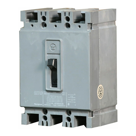
  9. Westinghouse DB-50 User manual

Westinghouse DB-50 User manual

Other manuals for DB-50

5

Other Westinghouse Circuit Breaker manuals
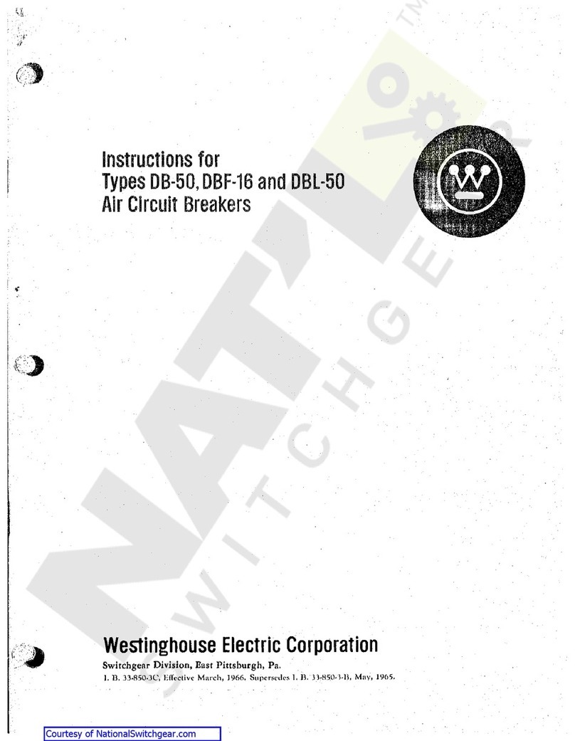
Westinghouse DB-50 User manual

Westinghouse

Westinghouse DB-50 User manual

Westinghouse DB-75 User manual

Westinghouse

Westinghouse DB-75 User manual

Westinghouse F-11 User manual

Westinghouse

Westinghouse F-11 User manual

Westinghouse F-122 User manual

Westinghouse

Westinghouse F-122 User manual

Westinghouse De-ion DB-15 User manual

Westinghouse

Westinghouse De-ion DB-15 User manual

Westinghouse VCP Series User manual

Westinghouse

Westinghouse VCP Series User manual

Westinghouse DH-P Series User manual

Westinghouse

Westinghouse DH-P Series User manual

Westinghouse DBN-1016 User manual

Westinghouse

Westinghouse DBN-1016 User manual

Westinghouse DB-75 User manual

Westinghouse

Westinghouse DB-75 User manual

Westinghouse DB-50 User manual

Westinghouse

Westinghouse DB-50 User manual

Westinghouse DK-25 User manual

Westinghouse

Westinghouse DK-25 User manual

Westinghouse DK-15 User manual

Westinghouse

Westinghouse DK-15 User manual

Westinghouse DB-75 User manual

Westinghouse

Westinghouse DB-75 User manual

Westinghouse De-ion 50-DH-350 User manual

Westinghouse

Westinghouse De-ion 50-DH-350 User manual

Westinghouse DH User manual

Westinghouse

Westinghouse DH User manual

Westinghouse Porcel-line DHP Series User manual

Westinghouse

Westinghouse Porcel-line DHP Series User manual

Westinghouse DB-50 User manual

Westinghouse

Westinghouse DB-50 User manual

Westinghouse De-ion DB-15 User manual

Westinghouse

Westinghouse De-ion DB-15 User manual

Westinghouse AB DE-ION Series User manual

Westinghouse

Westinghouse AB DE-ION Series User manual

Westinghouse DB-75 User manual

Westinghouse

Westinghouse DB-75 User manual

Westinghouse 50-DG-50 User manual

Westinghouse

Westinghouse 50-DG-50 User manual

Westinghouse De-ion DB-15 User manual

Westinghouse

Westinghouse De-ion DB-15 User manual

Westinghouse CAS-8 User manual

Westinghouse

Westinghouse CAS-8 User manual

Westinghouse DS-206 User manual

Westinghouse

Westinghouse DS-206 User manual
Popular Circuit Breaker manuals by other brands

Siemens 3VT9524-4TG30 quick start guide

Siemens

Siemens 3VT9524-4TG30 quick start guide

Acrel ASCB1 Series Installation and operation manual

Acrel

Acrel ASCB1 Series Installation and operation manual

ABB SACE Emax 2 E2.2 manual

ABB

ABB SACE Emax 2 E2.2 manual

Eaton NOVA LBS 15 Installation and operation instructions

Eaton

Eaton NOVA LBS 15 Installation and operation instructions

ABB SACE Emax E1 quick start guide

ABB

ABB SACE Emax E1 quick start guide

Siemens SIRIUS 3RV1742 Original operating instructions

Siemens

Siemens SIRIUS 3RV1742 Original operating instructions

WEG FHU ACW125 installation instructions

WEG

WEG FHU ACW125 installation instructions

TERASAKI NHP TemBreak PRO P160 Series installation instructions

TERASAKI

TERASAKI NHP TemBreak PRO P160 Series installation instructions

Siemens Sentron 3VA9157-0PK1 Series operating instructions

Siemens

Siemens Sentron 3VA9157-0PK1 Series operating instructions

hager TS 303 User instruction

hager

hager TS 303 User instruction

ETI EFI-4B Instructions for mounting

ETI

ETI EFI-4B Instructions for mounting

Gladiator GCB150 Installation instruction

Gladiator

Gladiator GCB150 Installation instruction

nader NDM3EU-225 operating instructions

nader

nader NDM3EU-225 operating instructions

Eaton 50DHP-VR Instruction handbook

Eaton

Eaton 50DHP-VR Instruction handbook

ABB SACE Emax 2 E6.2 Instruction handbook

ABB

ABB SACE Emax 2 E6.2 Instruction handbook

Gewiss 90 RCD Installation

Gewiss

Gewiss 90 RCD Installation

OEZ LFN Instructions for use

OEZ

OEZ LFN Instructions for use

Eaton Power Defense PDG2 Instruction leaflet

Eaton

Eaton Power Defense PDG2 Instruction leaflet

manuals.online logo
manuals.online logoBrands
  • About & Mission
  • Contact us
  • Privacy Policy
  • Terms and Conditions

Copyright 2025 Manuals.Online. All Rights Reserved.

*
£
*
%
i
T
%
'
»
4
I
J
tYuctio
fC
'
t
?
QOj
(
’
JV
3
a
>
t
t
*
?
<
-
ft
'
*
Type
DB
-
50
"
De
-
ion
"
Air
Circuit
Breaker
v
'
}
*
'
<
r
.
i
?
i
:
«
V
1600
Ampere
Frame
Size
•
i
$
4
9
•
n
•
fci
600
Volts
A
-
C
£
4
1
f
250
Volts
D
-
C
1
-
.
!
J
/
!
Interrupting
Rating
50
,
000
Amperes
>
v
,
5
*
5
ft
•
c
f
-
a
*
s
WESTIN
6
HOUSE
ELECTRIC
CORPORATION
Switchgear
Apparatus
Departments
,
East
Pittsburgh
,
Pa
.
I
.
B
.
33
-
850
-
3
Supersedes
I
.
B
.
35
-
230
-
C
3
July
,
1959
Printed
In
U
.
S
.
A
.
Courtesy of NationalSwitchgear.com
<
TABLE
OF
CONTENTS
Page
Description
Port
I
—
Receiving
,
Handling
,
and
Storing
6
Inspection
.
Storing
.
.
6
Part
II
—
Installation
7
Connections
Part
III
—
Maintenance
10
Pole
Unit
Contacts
Maintenance
of
Contacts
Operating
Mechanism
Closing
Spring
Mechanism
*
Closing
Solenoid
Overcurxent
Tripping
Device
Installation
and
Removal
Construction
Time
-
Current
Classification
Operation
Time
Current
Characteristics
Adjustment
of
Calibration
Settings
Maintenance
Control
Relay
-
Shunt
Trip
Attachment
Undervoltage
Trip
Attachment
.
Undervoltage
Time
Delay
Attachment
Reverse
Current
Trip
Attachment
.
.
.
Field
Discharge
Switch
.
.
..
Auxiliary
Switch
Alarm
Switch
Attachment
Electric
Lockout
Attachment
Key
Lock
Attachment
Key
Interlock
Attachment
Rectifier
Unit
for
A
-
c
Undervoltage
and
A
-
c
Electric
Lockout
Attachments
10
10
10
i
10
10
11
13
15
15
17
17
19
21
21
22
23
24
24
24
24
28
28
28
28
29
i
2
Courtesy of NationalSwitchgear.com
:
I
LIST
OF
ILLUSTRATIONS
i
Poge
Figure
8
DB
-
50
Outline
Dimensions
and
Mounting
Details
Typical
Wiring
Diagrams
-
Type
DB
-
50
Circuit
Breaker
Cross
-
Sectional
View
of
Type
DB
-
50
Circuit
Breaker
Type
DB
-
50
Spring
Closing
Mechanism
Series
Overcurrent
Tripping
Device
with
Long
Delay
and
Instantaneous
Elements
Series
Overcurrent
Tripping
Device
Showing
the
Assembly
of
Calibration
Case
to
Magnetic
Circuit
Cross
-
Sectional
View
of
Series
Overcurrent
Tripping
Device
with
Long
Delay
and
Instantaneous
Elements
Tripping
Characteristics
of
Standard
Series
Overcurrent
Tripping
Device
with
Long
Delay
and
Instantaneous
Elements
.
Tripping
Characteristics
of
Selective
Series
Overcurrent
Tripping
Device
with
Long
Delay
and
Short
Delay
Elements
Tripping
Characteristics
of
Special
Series
Overcurrent
Tripping
Device
with
Instantaneous
Element
Only
Schematic
Diagram
of
Standard
Series
Overcurrent
Tripping
Device
with
Adjustable
Long
Delay
and
Adjustable
Instantaneous
Elements
.
.
,
Schematic
Diagram
of
Selective
Series
Overcurrent
Tripping
Device
with
Adjustable
Long
Delay
and
Adjustable
Short
Delay
Elements
Schematic
Diagram
of
Special
Series
Overcurrent
Tripping
Device
with
Instantaneous
Element
Only
Instantaneous
Pick
-
Up
Per
cent
of
Coil
Rating
vs
Scale
Settings
Obtained
by
means
of
Standard
Instantaneous
Adjusting
Knob
Closing
Solenoid
-
Construction
Details
Control
Relay
-
Adjustment
and
Construction
Details
Shunt
Trip
Attachment
-
Construction
Details
Undervoltage
Trip
Attachment
-
Construction
Details
Undervoltage
Time
Delay
Attachment
-
Construction
Details
Reverse
Current
Trip
Attachment
-
Construction
Details
Field
Discharge
Switch
-
Construction
Details
Auxiliary
Switch
-
Construction
Details
Alarm
Switch
Attachment
-
Construction
Details
Construction
Details
1
9
2
11
3
12
3
A
4
13
5
13
6
14
7
14
8
15
9
15
10
16
11
18
12
18
13
19
14
20
15
22
16
23
17
25
18
26
26
19
20
27
21
27
22
29
23
Electric
Lockout
Attachment
Key
Lock
or
Key
Interlock
Attachment
-
Construction
Details
Rectifier
Unit
for
A
-
c
Undervoltage
and
A
-
c
Electric
Lockout
Attachments
.
.
30
31
24
32
25
3
Courtesy of NationalSwitchgear.com
<
I
(
£
STS
•
I
•
<
4
Courtesy of NationalSwitchgear.com
”
DB
”
AIR
CIRCUIT
BREAKER
WESTINGHOUSE
Type
"
DB
”
Air
Circuit
Breaker
Type
"
DB
”
air
circuit
breaker
is
designed
to
give
continuous
and
reliable
service
as
the
protective
link
between
the
power
source
and
associated
productive
equipment
.
This
breaker
is
built
to
operate
with
a
minimum
of
maintenance
,
while
at
the
same
time
its
simplified
construction
permits
maximum
accessibility
for
inspection
and
adjustment
when
required
.
The
ease
with
which
attachments
may
be
added
or
removed
is
an
outstanding
feature
of
the
,
TDB
,
T
design
.
For
the
greatest
measure
of
safety
to
operating
personnel
and
also
to
minimize
maintenance
requirements
,
the
breaker
should
be
mounted
in
an
enclosure
suitable
to
local
operating
conditions
.
A
selection
of
standard
enclosures
is
available
for
various
applications
.
Important
:
To
assure
proper
functioning
,
inspect
each
breaker
at
regular
intervals
in
accordance
with
a
systematic
maintenance
schedule
.
The
frequency
and
character
of
the
inspections
will
for
the
most
part
be
determined
by
the
severity
of
the
duty
performed
.
The
minimum
requirements
,
however
,
should
consist
of
a
light
monthly
inspection
,
with
a
thorough
inspection
semi
-
annually
.
Occasional
checks
on
calibration
as
well
as
on
coordination
and
freedom
of
all
moving
parts
,
must
be
included
in
the
maintenance
schedule
.
Consult
Westinghouse
engineering
and
service
personnel
for
recommendations
pertaining
to
special
operating
or
maintenance
conditions
.
5
Courtesy of NationalSwitchgear.com
RECEIVING
,
HANDLING
,
AND
STORING
<
PART
I
—
RECEIVING
,
HANDLING
,
AND
STORING
Type
"
DB
-
50
"
air
circuit
breakers
,
with
all
attachments
mounted
in
place
,
are
shipped
in
wooden
crates
.
a
.
Observe
whether
all
parts
are
in
proper
alignment
and
move
freely
.
Make
certain
that
the
studs
have
not
been
forced
out
of
alignment
.
b
.
Important
:
To
avoid
damage
to
the
breakers
,
do
not
use
hooks
in
handling
.
c
.
Be
sure
that
the
contacts
are
clean
and
properly
aligned
.
For
a
description
of
contact
alignment
,
refer
to
"
Contacts
”
,
Page
10
.
Net
weights
of
Type
DB
-
50
are
given
in
Table
No
.
1
below
.
3
.
If
the
contacts
are
in
alignment
and
all
parts
move
freely
,
continue
the
clockwise
ro
-
tation
until
the
breaker
is
latched
.
TABLE
NO
.
1
NET
WEIGHTS
TYPE
DB
-
50
4
.
Return
the
manual
operating
handle
to
the
neutral
position
,
then
rotate
counterclockwise
to
trip
the
breaker
.
3
-
Pole
280
lbs
.
3
S
5
lbs
.
2
-
Pole
220
lbs
.
298
lbs
.
MANUAL
ELECTRIC
a
.
The
toggle
linkage
should
collapse
and
the
moving
contact
assembly
move
freely
to
the
full
open
position
.
This
should
be
followed
immediately
by
complete
resetting
of
the
links
in
the
toggle
mechanism
as
the
handle
is
re
-
turned
to
the
neutral
position
.
Immediately
upon
receipt
,
examine
shipment
for
any
loss
or
damage
incurred
during
transit
.
If
injury
or
rough
handling
is
evident
,
file
a
damage
claim
at
once
with
the
transportation
company
and
notify
the
nearest
Westinghouse
Sales
Office
.
b
.
The
links
must
always
be
free
to
move
without
friction
or
binding
.
When
unpacking
,
be
sure
that
no
loose
parts
are
missing
or
left
in
the
packing
material
.
Report
all
shortages
at
once
.
Blow
out
any
dust
or
particles
of
packing
material
that
may
have
accumulated
on
the
circuit
breaker
parts
.
I
5
.
Check
the
attachments
for
operation
in
accordance
with
the
appropriate
instructions
as
given
under
r
'
Maintenance
"
,
Part
Three
of
this
book
.
NOTE
:
It
is
not
advisable
to
lubricate
any
parts
of
the
breaker
.
The
lubrication
supplied
during
factory
assembly
is
sufficient
for
years
of
service
.
The
lubricant
is
of
a
special
form
which
is
used
sparingly
.
The
addition
of
oil
will
only
promote
the
accumulation
of
dust
and
dirt
.
INSPECTION
The
"
DB
"
breaker
assembly
consists
of
a
coordinated
group
of
sub
-
assemblies
mounted
on
a
steel
supporting
panel
.
The
complete
breaker
assembly
is
to
be
mounted
with
the
steel
panel
in
a
vertical
position
.
All
inspec
-
tions
for
proper
operation
should
,
therefore
,
be
made
with
the
breaker
in
this
position
.
Final
inspection
should
preferably
be
made
with
the
breaker
in
its
permanent
mounting
.
STORING
If
circuit
breakers
are
not
to
be
installed
in
their
permanent
location
at
once
,
they
should
be
carefully
inspected
for
loose
or
damaged
parts
and
then
stored
in
a
clean
dry
place
in
an
upright
position
to
avoid
damage
to
the
cir
-
cuit
breaker
parts
.
A
covering
of
paper
will
prevent
dust
from
settling
on
the
circuit
breaker
parts
and
is
preferred
to
packing
or
other
ma
-
terials
that
are
apt
to
absorb
moisture
.
Inspect
the
breaker
as
follows
:
1
.
Raise
and
lower
the
trip
bar
by
hand
to
make
sure
that
it
does
not
bind
.
2
.
Rotate
the
manual
operating
handle
slowly
in
a
clockwise
direction
to
move
the
contacts
toward
the
closed
position
.
I
6
Courtesy of NationalSwitchgear.com
"
DB
”
AIR
CIRCUIT
BREAKER
PART
II
—
INSTALLATION
Type
"
DB
-
50
"
circuit
breakers
are
furnished
as
complete
unit
assemblies
and
the
installation
consists
of
:
(
1
)
bolting
them
to
the
supporting
framework
or
structure
;
(
2
)
connecting
the
current
-
carrying
cables
or
bus
bars
;
and
(
3
)
completing
any
secondary
control
wiring
that
may
be
necessary
.
CAUTION
:
During
installation
,
the
circuit
breaker
should
be
in
the
open
position
.
Be
sure
to
de
-
energize
the
load
and
control
leads
to
be
connected
,
and
also
the
section
of
the
switchboard
where
installation
is
being
made
.
CONNECTIONS
Typical
circuit
breaker
wiring
diagrams
are
shown
in
Fig
.
2
.
The
connecting
cables
or
bus
bars
should
have
adequate
current
-
carrying
capacity
,
otherwise
,
heat
will
be
conducted
to
the
circuit
breaker
resulting
in
possible
exces
-
sive
temperature
rise
.
Connecting
cables
or
bus
bars
must
be
supported
so
that
the
circuit
breaker
studs
will
not
be
subjected
to
unneces
-
sary
stresses
.
Mounting
dimensions
and
details
of
the
front
enclosure
cutouts
are
shown
in
Fig
.
1
.
To
prevent
distortion
of
the
breaker
panel
,
the
supporting
structure
should
be
checked
for
alignment
.
The
circuit
breaker
studs
and
all
connections
should
be
clean
,
smooth
,
and
free
from
burrs
to
assure
full
contact
area
.
They
should
be
firmly
clamped
or
bolted
in
place
to
prevent
excessive
heating
.
TABLE
NO
.
2
CLOSING
SOLENOID
CONTROL
VOLTAGES
AND
CLOSING
CURRENTS
CURRENT
IN
AMPERES
AT
NORMAL
VOLTAGE
FOR
OB
-
50
BREAKER
MINIMUM
VOLTAGE
AT
COIL
TERMINALS
NOMINAL
VOLTAGE
Close
Trip
Close
Close
Trip
S
H
24
V
.
D
-
C
48
V
.
D
-
C
125
V
.
D
-
C
250
V
.
D
-
C
II
5
V
.
60
Cy
230
V
.
60
Cy
460
V
.
60
Cy
*
Selenium
Rectox
is
provided
.
S
=
Standard
-
burden
closing
coil
.
H
=
High
-
burden
closing
coil
.
MUST
be
specified
for
each
DB
-
50
breaker
having
short
time
delay
devices
and
for
each
A
-
C
op
-
erated
DB
-
50
breaker
where
closing
power
is
taken
from
the
l
ine
side
of
breaker
and
the
regulation
is
questionable
.
9.5
14
«
•
28
4.9
••
•
2.2
124
90
70
35
62
18
1.1
180
140
3.4
95
124
*
35
*
190
1.7
190
18
*
62
*
380
380
.
7
7
Courtesy of NationalSwitchgear.com
INSTALLATION
<
Approximate
Only
.
Do
Not
Use
for
Construction
Purposes
.
E
3
E
3
£
9
B
9
-
E
3
4
*
E
3
E
3
-
—
E
3
'
THE
FOLLOWING
ATTACHMENTS
CAN
IE
SUPPLIED
WITHOUT
IN
-
CREASING
OVERALL
DIMENSIONS
:
Switches
{
12
-
Cir
-
lTlmnrn
)
Current
stud
arrange
-
ment
—
2
-
pole
breaker
with
Held
aisobarge
con
-
tacts
Current
stud
arrange
-
ment
—
2
-
pole
breaker
Current
stud
arrange
-
ment
—
2
-
pole
breaker
witk
reverse
current
at
-
tachment
{
Standard
NEMA
arrangement
)
Auxiliary
cult
Mi
Dio
.
opening
for
f
key
lock
or
key
Interlock
when
required
.
•
Shunt
Trip
•
Under
voltage
Trip
(
With
Without
Time
Delay
)
5
±
5
or
8
•
Alarm
Switch
•
Key
Lock
or
Key
Interlock
•
Field
Discharge
Contact
•
Electric
Lockout
•
Operation
Counter
7
\
'
TV
/
£
2
E
2
—
E
3
—
E
3
^
2
3
l
'
/
A
4
±
R
.
*
4
+
tof
Hondle
!
3
|
E
2
—
E
&
E
3
—
E
3
—
E
53
-
Center
Line
of
Breoker
Current
stud
arrange
-
ment
—
2
-
pole
breaker
with
reverse
current
at
-
taohment
(
Standard
ABS
-
A
1
EE
Marine
rangement
)
Current
stud
arrange
-
ment
—
3
-
pole
breaker
Cut
-
out
in
dead
front
door
of
cover
ar
-
Llve
parts
or
combustible
material
must
not
be
located
In
this
area
,
unless
gas
deflecting
barriers
are
provided
here
.
<
21
51
«
>
ia
.
l
2
)
18
9
Provision
for
padlocking
breoker
hondle
in
tripped
position
.
Padlocks
furnished
by
customer
.
4
*
|
7
i
—
8
j
|
Dia
.
t
6
)
Mounting
Holes
3
t
4
6
|
6
6
/
>
|
2
Agpro
»
.
_
_
^
|
£
g
|
Dia
.
(
2
)
%
r
"
"
*
"
7
i
io
32
i
3
4
I
I
±
Is
XJ
2
I
1
n
ij
at
©
4
Cutout
in
Customer
'
s
Mounting
Ponet
4
PL
Arc
13
|
Chute
t
]
l
9
I
I
-
!
*
i
il
li
5
E
Position
—
Indicator
T
8
li
^
3
’
03
1
o
LJ
li
I
.
q
Center
Line
8
i
tl
A
of
Hondle
27
8
q
i
10
s
8
i
P
!
4
Face
Plate
4
B
«
!
To
Trlp
I
=
i
;
To
Close
*
I
4
i
T
*
«
1
2
»
fs
Overcurrent
Trip
Reverse
—
Current
Trip
t
i
Solenoid
L
°
_
L
.
Steel
Base
Mounting
Line
5
a
-
9
l
Center
Pole
Studs
(
Side
View
)
For
field
discharge
contacts
*
4
|
5
U
Min
.
19
i
2
16
Boundary
surfaces
of
the
circuit
breoker
are
to
be
considered
ground
potential
Door
or
front
cover
supplied
by
switchboard
builder
.
Fig
.
1
—
DB
-
50
Outline
Dimensions
and
Mounting
8
Courtesy of NationalSwitchgear.com
FIG
.
1
fljTr
T
CONNECTION
DIAGRAM
(
EV
.
)
]
%
;
COFN
^
BUC
FIG
.
10
FIXED
PANEL
SHUNT
TRIP
.
|
.
„
rr
'
r
m
TP
3
*
0
»
A
-
ALARM
CONTACT
DOES
NOT
CLOSE
WHEN
BREAKER
1
S
TRIPPED
MANUALLY
OR
BY
THE
SHUNT
TRIP
t
\
W
;
)
“
“
I
3
i
I
(
TCJ
SF
i
«
-
I
i
1
4
-
C
-
/
L
J
l
ri
4
l
I
I
11
TOP
'
*
“
TN
—
y
—
J
^
5
*
-
CURRENT
LIMITING
RESISTORS
S
FUSES
TO
BE
USED
ONLY
WHEN
CONTROL
SOURCE
15
FROM
SWGR
.
BUS
.
AUX
i
TSi
-
L
sw
§
fLO
)
VTy
SCHEMATIC
CONNECTION
lMA
6
ftAM
CF
-
V
.
)
S
-
G
i
gift
BOT
1
AUX
:
SW
.
Fid
.
11
RKyERSE
.
CUBBENT
>
x
4
-
r
—
;
>
r
“
I
or
L
\
POTENTIAL
COIL
.
3
»
p
COIL
WTEMTIAI
I
COIL
.
I
OPERATION
SEQUENCE
1
.
CONTROL
SWITCH
C
.
S
.
-
C
CLOSED
.
2
.
*
X
*
RELAY
PICKS
UP
5
SEALS
IN
THRU
AUX
.
CONTACTX
*
3
|
400
aRE
5
.
3
.
CLOSING
COIL
ENERGIZED
THRU
^
“
CONTACT
CLOSING
BREAKER
.
4
-
.
IN
CLOSING
BKR
.
CLOSING
MECH
-
M
ECH
AN
ICALLY
TRIPS
"
X
”
CONTACTS
FREE
OF
'
X
‘
COIL
,
INTERRUPTING
CLOSING
CIRCUITS
.
5
.
WITH
BKR
.
IN
CLOSED
POSITION
,
THE
BKR
.
CLOSING
MECH
.
IS
LATCHED
UP
AND
"
X
"
CONTACTS
REMAIN
TRIP
FREE
FROM
'
XTQIl
6
.
WHEN
BKR
.
I
5
TRIPPED
CLOSING
MECH
.
DROPS
PERMITTING
'
X
"
CONTACTS
TO
RESET
PROVIDED
'
*
'
COIL
IS
DE
-
ENERGIZED
.
s
-
twins
SCHEMATIC
eaSA
L
_
ifiJ
4
—
4
SCHEMATIC
.
at
CON
jWcTfQKI
-
pLABK
^
U
TCT
FIG
.
i
>
.
DjC
.
UNpERVQl
.
TAGE
9
rff
©
7
rG
TP
ffCJ
.
X
FUSE
*
LEGEHD
Xr
CONTROL
RELAY
.
CC
-
CLOSING
COIL
.
TC
-
TRIP
COIL
.
C
5
-
CONTROL
SWITCH
.
,
7
cVt
)
r
^
BWSSS
8
W
^
4
#
-
&
*
@
*
1
±
cs
C
CS
.
g
%
8
cm
CTO
SCHEMATIC
uw
CONNECTION
DIAGRAM
o
CO
T
R
-
1
>
3
*
Fb
U
.
VrUNDERVOLTAGE
.
L
.
O
.
-
LOCKOUT
.
A
.
S
.
-
ALARM
SWITCH
a
-
WAKE
CONTACT
*
b
-
BREAK
CONT
.
-
LZZ
}
JC
FIG
.
12
ALARM
.
A
-
FOR
~
|
A
-
5
.
OPER
.
SEE
I
NOTE
A
|
PAGE
1
.
ELEC
.
PESET
ALARM
SW
.
V
|
)
|
rfm
>
>
4
-
TP
7
»
a
XMCCJ
J
£
—
I
5
-
I
*
v
l
TN
CJ
bf
=
3
?
J
TN
.
_
‘
~
*
~
s
ATI
C
.
I
PAGE
1
AS
.
Hqp
1
1
CONTROL
VOLTAGES
I
25
-
250
V
-
D
.
C
.
|
3
j
-
A
~
28
G
1
.
CONNECTION
DIAGRAM
.
^
F
-
V
.
7
m
5
*
5
m
co
Fig
.
2
—
Typical
Wiring
Diagrams
—
Type
DB
-
50
Circuit
Breaker
Courtesy of NationalSwitchgear.com
MAINTENANCE
<
PART
III
—
MAINTENANCE
CLOSING
SPRING
MECHANISM
POLE
UNIT
Each
pole
unit
is
mounted
on
a
separate
molded
base
through
which
the
breaker
studs
pass
.
(
See
Fig
.
3
.
)
The
molded
bases
are
attached
to
the
steel
mounting
panel
and
provide
insulation
for
the
breaker
studs
.
The
closing
spring
mechanism
is
shown
in
Fig
.
3
A
.
Rotating
the
closing
handle
clockwise
raises
the
lift
link
and
lower
spring
guide
to
compress
the
closing
spring
.
Near
the
end
of
the
closing
stroke
the
top
end
of
the
lift
link
strikes
the
first
toggle
lever
to
start
the
breaker
closing
.
As
the
breaker
closes
the
push
rod
raises
the
toggle
link
and
push
link
out
of
the
toggle
which
permits
the
closing
spring
to
complete
the
breaker
closing
.
The
upper
stud
and
contact
are
attached
to
the
molded
base
by
two
bolts
.
The
moving
contact
is
pivoted
on
the
molded
base
and
at
-
tached
to
the
cross
bar
through
insulating
links
.
The
series
coil
and
lower
stud
are
fastened
to
the
molded
base
by
four
bolts
.
CONTACTS
.
(
See
Fig
.
3
.
)
The
DB
-
50
arc
-
ing
contact
should
touch
first
on
closing
,
open
last
on
opening
.
Contact
pressure
on
the
mains
is
maintained
by
adjusting
gap
G
to
be
.
984
-
1.000
inch
.
This
gap
is
adjusted
by
removing
the
cross
bar
and
screwing
the
insulating
link
in
or
out
on
the
stud
.
Be
sure
to
tighten
the
lock
nuts
after
each
adjustment
.
Slow
emergency
operation
to
check
the
con
-
tact
sequence
can
be
obtained
by
exerting
a
slight
closing
pressure
on
the
closing
handle
and
simultaneously
pushing
forward
on
the
breaker
cross
bar
to
start
the
breaker
closing
.
MAINTENANCE
:
Oil
the
pins
and
slides
every
10
,
000
operations
.
CLOSING
SOLENOID
Do
not
over
-
adjust
as
this
will
cause
the
con
-
tact
springs
to
compress
to
the
solid
position
and
thus
increase
the
closing
effort
.
Check
for
over
-
adjustment
by
prying
the
stationary
arc
tips
open
to
at
least
1
/
16
-
inch
gap
.
MAINTENANCE
OF
CONTACTS
.
Rough
or
high
spots
should
be
removed
with
a
file
or
sandpaper
.
To
replace
the
arcing
contacts
,
open
the
breaker
,
remove
the
arc
chutes
and
then
the
stationary
arcing
contacts
.
Close
the
breaker
and
remove
the
moving
arcing
contacts
.
The
new
contacts
can
then
be
added
in
the
reverse
order
.
The
closing
solenoid
(
see
Fig
.
14
)
is
non
-
adjustable
.
It
is
designed
for
intermittent
duty
only
.
Check
for
loose
bolts
.
To
remove
closing
coil
,
trip
breaker
.
Dis
-
connect
closing
coil
leads
from
control
circuit
wiring
.
Take
off
bolts
(
18
)
,
washers
(
19
)
,
relay
release
arm
(
17
)
,
bolts
(
10
)
,
washers
(
11
)
and
plate
(
2
)
.
Drop
closing
coil
(
16
)
with
brass
tube
(
5
)
.
In
replacing
closing
coil
be
sure
to
replace
brass
tube
(
5
)
so
that
stationary
core
(
4
)
and
moving
core
(
22
)
are
aligned
in
the
tube
.
Be
careful
not
to
disturb
or
bend
plunger
(
23
)
.
Re
-
assemble
closing
coil
and
details
in
reverse
order
from
removal
.
CAUTION
:
All
power
should
be
removed
when
changing
,
maintaining
or
adjusting
contacts
.
OPERATING
MECHANISM
If
the
circuit
breaker
is
permanently
mounted
near
the
floor
so
that
the
closing
coil
cannot
be
dropped
far
enough
for
removal
then
follow
these
directions
.
Trip
breaker
and
remove
breaker
manual
operating
handle
and
breaker
face
plate
.
Disconnect
closing
coil
leads
from
control
cir
-
cuit
wiring
.
Take
off
bolts
(
18
)
,
washers
(
19
)
,
relay
release
arm
(
17
)
,
bolts
(
10
)
,
washers
(
11
)
and
plate
(
2
)
.
Drop
closing
coil
(
16
)
with
brass
tube
(
5
)
so
that
pin
(
6
)
is
exposed
.
Push
pin
(
6
)
to
right
into
hole
on
right
hand
side
of
solenoid
yoke
(
1
)
and
allow
moving
core
(
22
)
to
drop
into
brass
tube
(
5
)
.
Pick
up
closing
The
operating
mechanism
(
see
Fig
.
3
)
is
non
-
adjustable
and
consists
of
a
series
of
non
-
ferrous
links
designed
to
secure
low
closing
and
tripping
forces
.
To
check
for
friction
,
raise
the
trip
bar
and
slowly
rotate
the
manual
operating
handle
in
close
and
trip
direction
.
The
linkage
should
follow
the
handle
without
sticking
.
A
small
quantity
of
lubricant
is
placed
on
the
handle
shaft
,
the
roller
lever
roller
,
and
the
latch
plate
at
the
factory
.
I
10
Courtesy of NationalSwitchgear.com