manuals.online logo
Brands
  1. Home
  2. •
  3. Brands
  4. •
  5. Westinghouse
  6. •
  7. Circuit Breaker
  8. •
  9. Westinghouse DK-15 User manual

Westinghouse DK-15 User manual

'
SSSJfvi
'
,
:
;
TYPE
DK
-
15
AND
DK
-
25
AIR
CIRCUIT
BREAKER
"
:
-
vr
-
1
;
s
•
V
.
:
A
.
:
l
•
'
•
i
:
1
.
>
?
,
*
.
=
-
.
u
0
i
A
.
4
Si
--
m
"
A
-
-
:
:
•
r
•
•
-
.
•
Vi
=
;
-
.
:
••
:
;
A
-
i
-
•
P
-
.
j
*
r
-
•
A
’
.
••
'
•
:
V
.
;
f
.
.
i
-
}
yjj
600
-
Volt
A
-
C
„
250
-
Volt
D
-
C
.
Breaks
.
®
*
-
;
®
MslpMS
®
S
!
m
.
-
,
T
,
:
.
;
'
-
.
IV
®
«
<
safest
*
fc
'
ssWl
-
WSilS
:
;
;
:
Fig
.
1
—
3
-
Pole
,
600
-
Amp
v
'
..
•
v
.•
:
.
.
.
•
;
?
.•
*
'
,
v
"
f
\
j
%
•
lv
r
y
i
.
.
rt
&
iM
&
AA
rnwy
,
*
;
;
:
Instruction
Book
5965
-
F
Filing
No
,
35
-
000
•
-
,
-
v
.
'
?
-
>
!
>
'
•
-
•
r
'
•
,
-
.
i
-
•
-
•
••
-
r
<
1
\
\
i
.
!
•
:
•
j
-
'
p
-
w
\
’
"
!
•
y
\
'
,
r
:
•
-
'
-
N
'
:
1
•
V
.
:
'
>
•
-
P
,
v
>
'
.
*
t
.
'
;
&
&
>
'
>
-
•
f
-
.
'
V
y
:
-
iife
'
tyjt
,
m
-
-
-
‘
'
yipplfyy
;
yr
¥
•
•
/
•
l
-
.
*
•
.
*
.
?
.
r
Westinghouse
Electric
Corporation
Bast
Pit
tr
,
bu
rgh
,
Pa
'
vvnp
jv
'
V
''
•
r
-
•
;
V
.
V
:
.
V
-
•
"
1
•
•
•
••
•
:
:
•
s
'
-
.
Courtesy of NationalSwitchgear.com
/
'
<
f
/
7
‘
:
V
\
b
-
V
m
%
’
f
L
‘
'
"
i
••
r
.
V
\
•
*
*
V
O
'
—
•
*
Type
DK
-
IS
and
DK
-
25
Air
Cirpuit
Breaker
t
.
it
•
.
Genera
)
complete
with
all
attachments
,
adjusted
and
calibrated
on
ItB
It
1
B
designed
only
to
be
mounted
In
a
operation
must
be
made
v
;
’
i
|
4
!
l
,
'
is
a
The
DK
air
circuit
breaker
,
BeIf
-
contained
unit
,
and
hap
been
mounted
,
own
permanent
panel
at
the
factory
,
vertical
position
,
and
all
inspections
for
proper
with
the
breaker
main
panel
held
vertically
.
’
\
Unpacking
-
y
Care
must
be
exercised
when
unpacking
to
make
sure
that
no
parts
are
broken
or
damaged
,
and
an
Inspection
should
be
made
immediately
to
check
for
any
damage
in
,
transit
.
All
dust
and
dirt
should
be
carefully
blown
,
out
of
the
complete
assembly
,
especially
in
the
closing
toggle
link
-
age
overload
attachments
and
such
other
attachments
as
are
supplied
,
t
rif
The
lubrication
supplied
during
factory
assembly
,
where
necessary
,
is
a
special
-
This
will
be
’
found
sufficient
for
to
lubricate
any
parts
of
the
breaker
It
is
not
advisable
^
.
v
,
4
form
of
grease
which
is
used
sparingly
.
:
years
of
service
.
Additional
oil
will
only
promote
the
accumulation
.
of
dust
In
new
installations
,
the
breaker
must
be
carefully
protected
other
foreign
,
gritty
particles
that
,
may
.
.
add
and
dirt
.
from
plaster
,
,
concrete
and
friction
to
the
moving
parts
in
the
toggle
linkage
,
:
:
Inspection
i
•
Pinal
'
inspection
should
preferably
be
made
with
the
.
breaker
in
its
permanent
mounting
,
but
if
this
is
impossible
,
it
can
be
set
up
rigidly
in
.
a
vertical
position
while
.
the
inspection
is
made
.
'
:
;
v
•
r
*
Rotate
the
manual
operating
handle
slowly
in
a
clockwise
,
direc
-
tion
to
move
the
contacts
toward
the
closed
position
.
Check
the
movement
of
each
arc
tip
through
the
throat
of
the
MDe
-
ion
"
arc
Interrupting
chamber
to
make
sure
that
the
tips
do
not
rub
against
the
ceramite
aide
plates
.
Continue
the
closing
motion
until
the
moving
arc
tips
just
touch
the
.
sta
-
Check
the
main
contact
separation
at
approximately
1
/
8
Continue
the
handle
rotation
to
the
fully
tionary
arc
tips
,
inch
,
as
3
hown
on
Figs
.
2
and
5
.
closed
position
and
watch
the
main
contact
overtravel
as
evidenced
byrotary
motion
away
from
its
stop
,
adjacent
to
the
section
where
the
shunt
is
attached
.
4
\
:
S
'
•
i
T
Return
the
manually
operated
handle
to
the
neutral
,
position
:
:
and
rotate
counterclockwise
to
trip
the
breaker
.
-
The
toggle
linkage
;
|
should
collapse
and
the
moving
contact
assembly
move
freely
to
the
full
openvposi
-
tion
.
Tills
is
folloved
immediately
by
complete
resetting
of
the
,
(
links
,
in
the
toggle
mechanism
,
This
resetting
operation
is
accomplished
entirely
:
by
gravity
.
For
this
reason
the
links
must
alvays
be
free
to
move
^
without
friction
or
binding
,
Adjustment
of
Contacts
•
:
•
•
•
•
i
-
»
The
ar
$
tip
adjustment
should
be
made
as
shown
in
Figs
'
.
2
and
J
.
.
There
Is
no
adjustment
provided
for
the
main
contacts
,
and
under
ordinary
circumstances
these
main
contacts
will
last
the
life
of
the
breaker
without
repair
other
than
occasional
cleaning
.
Both
main
and
arcing
contacts
are
a
hfgh
silver
alloy
.
Replacement
of
Contacts
•
:
.
/
•
.
v
-
'
(
%
JS
<
4
.
The
sub
-
panel
,
barrier
and
"
De
-
ion
"
interrupting
assembly
;
may
be
removed
asaunit
by
taking
out
two
bolts
at
the
outer
ends
cf
the
sub
-
panel
This
gives
access
to
the
contacts
for
easy
Inspection
or
replacement
)
^
^
-
!
.
-
.
.
;
;
.
.
i
:
‘
Courtesy of NationalSwitchgear.com
/
j
.
«
i
-
'
"
V
:
V
,
'
>
•
*
•
/
%
..
r
*
I
I
1
•
X
:
-
.
S
'
.
•
*
>
Jt
A
1
.
.
x
'
Type
DK
45
and
DK
-
25
Air
Circuit
Breaker
>
.
V
.
:
r
-
:
I
y
.
i
.
>
.
i
:
s
i
\
;
•
)
The
moving
arc
tip
can
be
removed
by
taking
out
the
wire
clip
and
at
on
the
threaded
rod
,
removing
two
small
screws
that
hold
the
secondary
shunt
to
the
main
contact
,
and
removing
the
arc
tip
pin
.
The
stationary
•
arc
tip
may
be
removed
by
taking
out
four
flat
head
screws
.
The
new
items
may
be
replaced
In
the
reverse
order
.
Take
care
to
make
proper
adjustment
as
shown
in
Figs
.
?
and
j
>
,
und
set
all
poles
of
the
breaker
at
one
time
and
then
securely
lock
each
adjusting
nut
with
a
wire
clip
.
f
-
P
’
.
:
£
f
-
i
The
moving
main
contact
may
be
removed
by
taking
out
the
bolts
at
the
upper
end
of
the
trip
unit
,
removing
two
bolts
from
the
rear
that
hold
this
lower
section
to
the
panel
,
and
taking
out
the
pin
in
the
contact
arm
.
•
'
The
contact
and
shunt
can
now
be
removed
intact
and
replaced
in
the
reverse
The
stationary
main
contact
can
be
removed
by
taking
out
two
bolts
order
from
the
rear
of
the
panel
on
the
flat
stud
,
or
removing
the
finger
cluster
,
large
contact
nut
,
and
one
bolt
from
the
rear
of
the
panel
on
the
drawout
type
.
.
^
Replacement
is
made
with
a
complete
new
upper
stud
.
»
;
•
•
A
-
-
•
V
•
•
<
,
’
•
Adjustment
of
Toggle
Linkage
t
;
The
toggle
,
linkage
in
the
DK
circuit
breaker
is
,
a
series
of
links
so
arranged
'
that
,
the
closed
breaker
load
is
transmitted
through
successive
toggles
with
a
reduction
at
each
step
,
to
the
final
tripping
toggle
where
a
'
very
low
,
hut
consistent
,
load
is
maintained
with
one
simple
,
adjustment
;
,
This
adjusting
screw
will
be
found
in
the
front
of
the
main
frame
behind
the
.
face
plate
,
as
shown
in
Figs
.
2
and
3
.
This
adjustment
Is
set
slightly
over
'
toggle
to
produce
'
a
light
tripping
load
.
The
factory
adjustment
should
’
not
vary
in
service
,
.
but
can
easily
be
checked
or
readjusted
by
reference
to
the
’
.
.
sketches
.
.
pole
trip
finger
on
the
trip
bar
at
a
point
in
line
with
the
plunger
,
pqund
tripping
load
must
be
maintained
to
insure
proper
.
tripping
'
of
the
"
reaker
-
by
the
overload
trip
units
and
other
calibrated
attachments
,
V
,
.
\
.
-
,
v r
:
•
•
••
'
•
•
•
•
•
:
*
;
\
For
this
operation
,
use
a
small
spring
balance
applied
to
the
left
-
This
r
i
/
S
-
.
TfUrT
;
.
:
-
-
:
'
•
!
Dual
Overload
Tripping
Attachments
:
X
i
•
•
The
DK
circuit
breaker
is
supplied
with
either
of
.
.
two
distinct
,
types
of
adjustable
Inverse
time
delay
trip
units
:
-
(
l
)
oil
sucker
-
magnetic
dual
overload
,
and
(
2
)
thermal
-
magnetic
dual
overload
.
Both
types
are
suit
-
able
for
'
either
a
-
c
.
or
d
-
c
.
service
.
The
oil
sucker
type
of
time
delay
is
designed
for
all
standard
application
where
overcurrent
tripping
is
desired
with
time
delay
that
can
.
be
adjusted
to
a
minimum
,
approaching
zero
time
.
'
If
„
.
required
.
The
thermal
,
n
type
of
time
delay
,
on
the
other
hand
,
is
for
applies
lions
which
require
Uhusually
long
tripping
time
at
relatively
large
over
-
loads
,
associated
with
motor
starting
conditions
and
protections
.
In
both
>
cases
any
current
in
excess
of
ten
times
normal
rating
produces
Instantaneoua
*
3
§
£
4
fe
‘
.
tripping
•
%
«
,
-
?
*
'
:
:
#
.
r
.
•
r
Characteristics
of
Oil
Sucker
-
Magnetic
Dual
Overload
Fig
,
2
shows
the
arrangement
of
-
adjustments
on
this
tripping
,
attachment
,
and
Fig
.
6
represents
the
characteristic
inverse
time
delay
.
The
100
#
calibration
setting
is
the
normal
rating
of
the
.
trip
unit
,
and
that
value
of
current
will
ju
.
at
trip
the
breaker
with
no
oil
in
the
pot
.
Adjustment
of
the
thumb
screw
toward
the
200
£
calibration
setting
raises
the
minimum
tripping
current
in
minute
steps
as
desired
.
Rotation
of
the
molded
pot
?
properly
filled
with
oil
as
explained
on
the
.
drawing
,
varies
the
time
delay
between
0
and
.
100
^
.
Thus
,
any
desired
combination
of
-
min
lmum
tripping
current
ana
time
delay
can
be
selected
as
desired
.
.
*
:
-
;
•
:
>
;
i
!
:
.
.
'
'
•
Vyk
.
<
.
v
/
»
•
;
o
/
\
.
\
-
X
v
•
%
\
r
.
\
.
2
v
i
•
•
•
•
.
\
.
"
•
-
.
Courtesy of NationalSwitchgear.com
ifi
:
.
•
.
»
:
vf
••
>
••
•
••
/
'
•
!
Y
<
Ml
t
,
\
-
.
7
1
'
\
}
'
i
Type
DK
-
15
and
DK
-
25
Air
Circuit
Breaker
•
(
:
?
’
v
V
-
*
1
•
•
-
>
.
CharacteristicB
of
Thermal
-
Magnetic
Dual
Overload
S
.
V
«
•
The
general
arrangement
of
this
attachment
Is
shown
in
Pig
.
3
with
inverse
time
delay
characteristics
in
Fig
.
7
,
The
100
$
calibration
setting
of
the
pointer
on
the
scale
plate
is
the
normal
rating
of
the
trip
unit
,
Adjustment
of
the
thumb
screw
toward
the
maximum
calibration
setting
raises
the
minimum
tripping
current
in
minute
steps
as
desired
X
'
»
v
1
:
Ambient
correction
is
explained
in
Fig
.
3
as
1
$
.
increase
in
call
-
bration
for
each
2
°
C
.
rise
in
temperature
.
The
.
attachment
is
calibrated
for
2
^
°
C
.
ambient
,
-
but
if
it
is
desired
to
meet
the
calibration
character
-
'
istics
of
Fig
.
5
at
^
0
°
C
,
,
for
Instance
,
the
calibration
adjustment
should
approximately
108
$
for
minimum
tripping
at
normal
current
rating
.
«
be
set
at
i
The
calibration
adjustment
can
therefore
be
set
as
close
to
the
normal
running
current
of
the
motor
as
is
desired
,
depending
on
ambient
Complete
'
protection
is
thus
af
~
temperature
,
frequency
of
starting
,
etc
.
forded
under
all
conditions
of
operation
.
Full
details
for
adjustment
and
maintenance
netic
trip
attachment
are
explained
in
Fig
.
3
•
•
of
the
thermal
-
mag
-
’
•
«
‘
V
.
Replacement
of
Overload
Attachments
*
.
,
••
-
r
"
r
-
j
.
;
[
;
:
•
:
.
Both
types
of
overload
trip
units
may
be
easily
removed
.
From
.
.
,
thB
rear
,
take
out
two
screws
that
fasten
the
magnet
assembly
to
the
main
panel
and
disconnect
the
trip
unit
upper
terminal
where
it
is
bolted
-
to
the
main
pole
unit
shunt
section
.
.
In
the
case
of
'
draw
out
studs
the
'
finger
cluster
.
.
.
and
.
large
nut
must
also
-
be
removed
,
The
trip
unit
may
now
be
removed
^
^
Re
-
placement
is
s
.
lmply
the
reverse
of
this
procedure
.
f
:
•
>
*
.
’
'
v
W
'
•
•
.
t
After
the
unit
is
securely
mounted
to
the
panel
,
'
only
one
adjust
-
This
adjustment
rrr
ment
is
neces
.
sqry
for
correct
operation
with
the
breaker
,
consists
of
setting
the
screw
in
the
.
outer
end
of
the
.
trip
armature
lever
to
.
properly
trip
the
breaker
with
a
thin
spacer
between
the
armature
'
,
and
magnet
,
as
explained
in
Figs
.
2
and
3
•
i
®
"
••
:
"
T
'
-
uw
•
!
'
'
>
:
•
:
•
•
•
'
i
Electric
Closing
Mechanism
:
fv
V
*
.
Fledi
^
rlcally
operated
DK
circuit
entirely
self
-
contained
motor
mechanism
side
of
the
breaker
frame
.
breakers
are
-
equipped
with
an
(
fig
.
13
)
mounted
on
the
right
Two
of
the
toggle
linkage
pins
serve
as
dowels
to
accurately
locate
the
mechanism
insulating
base
.
By
removing
three
-
bolts
this
complete
,
assembly
can
be
taken
off
the
breaker
without
disengaging
any
;
parts
except
the
wiring
.
I
/
The
closing
motor
is
a
single
phase
commutator
type
'
shaft
motor
with
ball
bearings
sealed
with
lubricant
that
will
normally
last
the
life
of
the
apparatus
.
A
single
reduction
of
speed
between
.
.
.
the
motor
shaft
and
the
mechanism
crank
is
accomplished
with
a
worm
mounted
;
.
on
the
upper
end
of
the
motor
shaft
engaging
a
worm
gear
on
the
crank
shaf
.
t
This
gear
assembly
is
lubricated
on
'
assembly
sufficient
for
several
.
years
of
normal
,
service
.
An
oil
seal
on
the
motor
shaft
prevents
any
oil
,
/
;
-
or
•
grease
,
from
running
down
into
the
motor
windings
,
vertical
:
»
ivi
4
The
motor
is
.
designed
to
develop
an
exceptionally
high
torque
'
for
and
is
therefore
rated
for
intermittent
service
.
If
the
breaker
for
long
periods
,
the
'
A
centrifugal
speed
limiting
device
is
built
into
the
to
prevent
excessive
speed
.
at
normal
and
,
over
-
mechanism
after
the
limit
switch
liSSfep
t
its
size
,
is
closed
more
frequently
than
once
every
3
minutes
motor
may
overheat
,
lover
end
-
bell
of
the
motor
voltage
,
and
to
prevent
coasting
of
the
•
.
’
-
has
cut
off
the
motor
current
.
f
V
t
-
:
<
o
•
?
»
vC
;
.
•
>
•
•
;
:
v
•
•
•
mm
?
j
.
:
V
i
Courtesy of NationalSwitchgear.com
r
-
l
.
"
'
1
•
-
’
>
f
V
'
'
'
AA
1
;
'
:
-
v
•
-
v
,
r
'
.
-
fj
I
V
V
>
:
'
*
-
.
••
\
;
•
v
;
»
Type
DK
-
15
and
DK
-
25
Air
Circuit
Breaker
t
.
i
i
:
:
y
'
•
-
t
.
f
.
’
r
,
t
-
"
’
-
;
}
The
mechanism
crank
engages
a
hardened
steel
cam
on
the
roller
The
relative
motion
of
the
crank
roller
with
respect
to
this
cam
the
closing
mechanism
crank
shaft
a
.
ever
,
surface
is
to
produce
the
maximum
mechanical
advantage
when
A
limit
switch
segment
on
the
<
-
load
is
greatest
.
positively
carries
the
crank
roller
past
the
cam
after
a
closing
operation
so
that
the
breaker
can
be
closed
either
’
manually
or
electrically
without
The
only
requirement
is
that
the
*
Interference
or
mechanical
disengagement
limit
switch
must
be
allowed
to
cut
ofl
the
motor
closing
current
.
'
4
*
•
One
adjustment
between
the
motor
mechanism
and
the
breaker
roller
lever
should
be
checked
for
proper
operation
,
and
rotate
the
motor
by
hand
,
lover
end
and
rotating
the
armature
in
the
the
crank
roller
is
just
passing
over
the
heel
of
the
cam
.
from
l
/
6
k
to
1
/
52
inch
surface
at
this
point
.
he
unduly
high
,
and
if
too
much
clearance
is
present
fail
to
move
the
breaker
toggle
linkage
to
the
completely
closed
position
.
;
This
adjustment
is
maintained
by
adding
or
taking
out
a
spacer
between
the
molded
tiebar
and
the
cast
roller
lever
on
the
.
right
side
.
Close
the
breaker
manually
This
is
done
by
removing
the
plate
at
the
direction
of
the
arrow
,
until
There
should
be
clearance
between
the
roller
surface
and
.
the
If
binding
occurs
,
the
minimum
closing
voltage
will
the
mechanism
may
cam
1
1
The
motor
closing
current
is
given
in
the
following
t
^
ble
for
standard
control
voltage
ratings
:
.
1
•
;
;
:
.
y
Closing
Current
at
normal
Voltage
-
,
.
hvh
"
\
'
-
'
.
-
Mrui
-
lh
:
.
Voltage
Rating
.
110
Volt
,
-
A
-
c
220
Volt
,
12
b
Volt
,
D
-
c
.
250
'
Volt
yiflfe
'
:
mrn
.
1
.
JO
Amperes
Amperes
Amperes
-
*
•
15
'
rjnperes
•
•
1
c
:
A
-
c
*
.
»
1
*
30
r
-
A
y
;
K
:
••
c
.
>
Shunt
Trip
Attachment
*
:
•
.
The
shunt
trip
attachment
,
when
supplied
,
'
is
mounted
rigidly
to
the
breaker
frame
behind
the
face
plate
.
The
trip
bar
bracket
is
attached
to
Its
lower
end
.
V
/
hen
the
shunt
,
trip
is
not
supplied
,
its
place
is
taken
by
a
long
trip
rod
held
by
a
case
identical
in
outside
appearance
with
-
,
the
-
shunt
trip
case
,
Both
types
are
interchangeable
and
car
.
be
readily
removed
and
replaced
,
In
replacing
the
shunt
trip
assembly
,
make
sure
-
the
moving
.
..
>
.
core
and
trip
rod
assembly
is
free
to
move
without
binding
against
the
guide
-
holers
or
coll
,
V
-
'
•
'
'
’
-
v
.
.
-
J y
-
H
,
V
-
”
-
.
.
•
•
•
-
.
r
y
.
.
y
-
y
The
.
shunt
trip
is
designed
for
Intermittent
duty
.
'
The
trIppiri
&
)
'
current
-
;
must
’
,
always
be
cut
off
by
an
auxiliary
switch
on
the
breaker
.
'
The
£
f
|
^
>
pi
;
.
l
.
;
-
.
normal
-
tripping
-
currents
.
for
standard
control
voltages
are
:
'
ySSt
’
-
.
d
Voltage
Rating
t
r
A
n
.
:
’
:
yd
;
,
.
-
.
Tripping
Current
/
•
V
:
:
t
f
-
.
.
vV
’
.
'
••
•
•
110
Volt
,
A
-
c
.
220
Volt
,
A
-
c
.
125
Volt
,
D
-
c
.
25
C
Volt
,
D
-
c
.
7
Amperes
b
Amperes
'
2
,
b
Amperes
1
.
b
Amperes
.
1
:
•
'
v
'
'
Vn
-
b
'
'
'
:
r
'
.
.
;
pm
.
-
r
k
-
.
.
Wiring
Diagram
hi
;
:
t
%
The
standard
wiring
diagram
for
the
motor
mechanism
and
shunt
,
trip
attachments
are
giver
,
in
Fig
.
10
.
The
motor
control
circuit
can
be
upplied
with
a
special
relay
as
an
Integral
part
of
the
electrically
open
j
.
ted
breaker
that
prevents
reclosure
until
alter
the
external
•
control
bi
-
switch
has
been
opened
.
See
Fig
.
8
,
This
prevents
the
breaker
from
pumping
if
closed
against
a
high
overload
or
short
circuit
.
A
further
feature
of
the
control
wiring
is
the
prevention
of
electrically
inching
the
breaker
closed
-
after
the
moving
'
contact
assembly
has
started
to
close
.
'
?
•
•
:
N
yd
-
.
•
r
r
\
Courtesy of NationalSwitchgear.com
•
1
:
t
'
.
VV
•
-
-
lij
.
'
•
i
‘
i
I
I
,
”
‘
'
•
.
1
'
Type
DK
-
15
and
DK
-
25
Air
Circuit
Breaker
K
!
1
^
•
V
/
V
*
f
>
;
Undervoltage
Tripping
Attachment
Tiic
-
undervoltage
attachment
is
normally
mounted
on
the
main
panel
to
the
left
of
the
breaker
,
trjp
bar
3
f
the
control
voltage
,
drops
voltage
,
from
the
holding
coila
close
the
breaker
.
.
Now
allow
the
armature
magnet
under
action
of
.
the
spring
in
the
flexible
link
,
trip
,
by
this
dead
push
.
shortening
or
lengthening
the
flexible
link
detail
.
"
:
.
.
v
,
’
It
operates
to
trip
the
breaker
through
the
.
to
a
value
of
35
#
to
60
#
of
rated
.
To
check
the
adjustment
of
this
attoclimcnt
,
remove
the
voltage
hold
the
armature
against
the
magnet
by
hand
,
.
.
and
to
move
slowly
away
from
the
The
breaker
should
Adjustment
to
provide
this
operation
is
made
by
»
When
the
undervoltage
attachment
is
furnished
with
a
time
'
delay
tripping
feature
,
the
oil
dash
pot
should
be
removed
by
unscrewing
the
pot
when
the
above
.
adjustment
is
checked
.
Always
connect
the
undervoltage
ceils
.
'
to
-
the
line
side
of
the
breaker
.
Reverse
Current
Attachment
V
'
i
;
The
reverse
current
attachment
(
Pig
.
12
-
13
)
is
used
to
trip
the
breaker
when
the
direction
of
current
flow
in
that
pole
is
reversed
.
The
attachment
consists
of
£
magnet
energized
hy
a
voltage
coil
and
an
armature
energised
by
a
current
ceil
.
in
series
with
one
pole
of
the
breaker
.
:
:
When
the
series
c
'
oil
current
is
flowing
in
the
proper
direction
the
armature
.
tends
to
rotate
but
is
restrained
by
a
stop
.
'
When
the
series
current
is
re
-
.
versed
the
armature
is
rotated
in
the
opposite
direction
against
a
spring
to
trip
the
breaker
.
This
adjustment
is
calibrated
and
marked
on
the
scale
plate
at
TO
#
,
15
$
,
00
#
and
25
$
reverse
current
,
based
on
normal
.
current
rating
.
;
'
V
Tv
mm
.
S
.
.
;
Is
reset
after
a
‘
tripping
operation
This
can
be
.
accomplished
by
wiring
The
reverse
current
armature
the
voltage
coll
circuit
.
by
opening
the
voltBge
ceil
through
ar
.
auxiliary
switch
on
the
breaker
.
•
'
y
Field
Discharge
Switch
*
,
m
.
'
,
The
field
discharge
contact
(
Fig
.
13
-
14
)
is
normally
mounted
on
;
a
two
pole
breaker
in
the
space
left
vacant
above
the
breaker
toggle
linkage
.
Correct
adjustment
in
cne
"
direction
is
evidenced
by
opening
of
the
switch
contact
just
grior
to
.
the
arc
tips
touching
during
the
breaker
closing
Similarly
,
the
switch
must
make
oontact
before
the
breaker
contacts
1
/
8
"
curing
the
opening
motion
of
the
breaker
.
motion
part
more
than
»
•
imm
"
:
Auxiliary
Switch
The
PK
auxiliary
switch
shown
in
Fig
.
9
is
a
compact
molded
assembly
supplied
in
either
1
to
8
poles
and
is
rigidly
mounted
on
the
.
.
side
‘
of
the
main
breaker
frame
.
Each
pole
consists
of
two
silver
posts
in
.
the
sections
which
carry
the
terminal
sorevs
on
the
reverse
side
,
The
moving
contact
is
a
silver
,
bridging
member
,
Bpring
mounted
on
the
sliding
bar
,
and
motion
such
that
adequate
wiping
action
takes
with
an
eccentric
ro
3
place
when
the
switch
contact
is
made
.
•
^
[
7
—
4
.
ft
i
.
The
terminal
screws
are
readily
accessible
on
the
completely
as
-
sembled
breaker
and
adequate
wiring
space
is
provided
from
the
switch
assembly
through
wiring
holes
to
.
the
rear
of
the
main
panel
,
:
:
.
‘
?
N
Each
four
point
switch
is
normally
assembled
with
two
"
make
"
and
two
"
break
"
contacts
,
but
any
pole
may
be
reversed
by
removing
the
sliding
bar
.
ana
inverting
the
bridging
member
,
.
thus
making
possible
any
desired
.
ar
urangement
.
j
'
iX
'
.
-
'
•
/
•
•
-
•
t
-
V
•
;
V
:
v
Courtesy of NationalSwitchgear.com
I
'
.
Ci
'
\
•••
'
1
'
.
<
V
:
•
•
•
>
•
.
'
•••
•
*
•
•
•
'
i
V
*
:
•
v
:
V
i
.
.
:
4
>
Type
DK
*
15
and
DK
-
25
*
Air
Circuit
Breaker
*
•
r
.
(
•
•
;
3
t
*
:
\
;
i
m
>
V
tv
DK
’
ZS
AIR
OR
.
SKR
.
-
600
R
MR
FRA
ME
-
A
C
,
-
VC
,
ADJUSTMENTS
WITH
OIL
SUCKER
DUAL
OVERLOAD
V
.
K
i
'
t
£
>
.
\
.
•
i
•
!
>
:
r
\
ADJUST
THIS
NUT
TO
S
/
VC
THE
UCARANCC
SHOWN
TWEEN
MAIN
CONTACTS
WHEN
THE
ARC
7
/
PS
JUST
TOUCH
.
I
0
C
*
SCCUPCLV
•
.
o
111
o
•
r
I
>
*
’
%
.
*
\
•
‘
•
y
'
•
i
•
I
n
o
r
-
r
-
»
i
M
'
-
-
~
-
rf
7
^
**
t
o
I
W
&
i
<
o
>
i
.
.
.
j
,
AT
J
i
*
I
I
*
-
-
•
*
°
!
C
.
W
ADJUST
TH
/
S
SET
SCREW
SO
&
XR
W
/
LL
JUST
TP
/
P
ON
DEAD
PUSH
By
N
/
OV
'
NQ
ARMATURE
DOWN
-
WARD
/
N
DIRECTION
OE
AMOWt
t
.
W
/
TH
,
0
'
S
/
N
.
SPACER
BETWEEN
MASNET
AND
ARMATURE
.
LOCK
5
CT
SCREW
AND
REMOVE
SPACER
.
TH
/
S
ADJUSTMENT
MUST
8
F
MADE
T
/
Mi
*
THFTHJP
UNI
ADJUST
rNfSSET
.
SCREW
SO
&
KEA
KER
CAN
S
£
TR
/
RRJESS
W
/
TH
FORCE
JNJU
'
vCArex
?
;
COAV
TO
as
\
A
RRJL
/
CD
THRU
TRIP
^
F
/
NCFAi
THC
-
»
/
*
•
»
ECT
/
orJ
OF
ARROW
JLOCH
S
4
SC
usr
£
AY
WV
T
H
L
o
C
K
HU
/
r
&
•
/
FORC
APPL
Y
i
*
j
C
•
/
LOwi
TO
,
V
II
\
/
t
^
r
*
t
x
,
^
r
4
l
.
i
k
:
T
•
gass
r
L
.
THE
INST
,
TRIP
FOf
/
.
UJS
SET
AT
0
T
/
MEf
/
00
%
SAT
/
NQ
V
/
N
TH
/
S
TUBE
AND
/
5
NOT
\
|
ADJUSTABLE
.
1
-
POO
/
VJPS
TO
TRIP
r
t
JOK
/
S
.
JDK
B
ST
fro
/
-
.
7
S
ro
/
.
as
/
ret
AS
.
TSroJLXS
\
/
ro
/
.
s
l
,
7
f
ro
/
.
ZS
/
ro
/
S
1
>
%
POL
£
3
l
,
S
ro
/
/
#
a
l
3
1
;
4
'
X
4
•
s
ttuj
:
zn
:
ia
;
\
KX
>
be
U
>
40
2
«
»
RCMO
^
C
'
THf
MOLDED
ITl
POT
BY
ROTATlSIf
BY
TURN
JNfULATCD
HUT
TO
StTPOINT
HAND
TO
UNC
UP
THE
THREE
SPPIM
*
CLIPS
ER
AT
ANY
DEfIRED
’
TR
/
PR
/
HQ
CUR
.
'
WW
CORREJPOHCHHCr
NOTCHES
.
THE
IND
!
’
R
[
ST
AS
MARKED
ON
SCALE
PLATCI
CATOR
CUP
MUST
BE
RAISED
SUOHTLY
TO
CACH
TRIP
UNIT
IS
CALIBRATED
WITH
PASS
OYER
END
OR
MOLOCD
SCALE
.
77
EMOUS
THE
ITL
POT
DRY
,
IP
SUPPLIED
,
RAPPER
'
W
/
hl
'
H
£
P
CLEAN
POT
AND
SOPH
/
/
r
SCALE
PLATE
IS
REMOVED
.
BE
urtvCNEPS
*
v
/
7
N
D
/
1
SOUND
.
DPT
THOPOUCHLY
SURE
AND
RETURN
tT
TV
TRtfAME
AND
P
/
LL
TO
’
OU
LeYEC
”
/
TH
n
'
ESP
/
VENOoSE
TRIP
UNIT
.
IP
THERE
IS
A
SLOT
PVR
CUL
..
STYLE
ELZSJ
>
S
>
(
,
'
NEPLACE
POT
AND
SET
TO
S
)
NY
PES
/
NED
T
/
ME
DELAY
E
7
rVN
1
O
TO
LOO
.
THE
SCALE
PLATE
MOUNTING
SCREWS
REASSEMBLE
WITH
PLATE
.
DOYEN
AS
FAR
AS
THE
SLOT
WILL
ALLOW
/
.
r
•
.
v
.
<
"
-
1
*
*
:
Fig
.
2
-
Adjustments
with
.
Oil
Sucker
M
&
gnetic
IXial
Overload
s
}
-
'
Drawing
A
-
D
-
2515
-
5
.
j
-
v
:
U
Ur
&
jk
N
-
f
••
•
.
.
V
w
r
»
;
;
1
Courtesy of NationalSwitchgear.com
'
*
.
<
»
i
:
I
.
[
*
I
V
:
O
'
t
-
:
Type
DK
-
i
5
and
DK
-
25
Air
Circuit
Breaker
1
.
;
*
:
•
A
"
;
.
V
*
!
:
-
iv
;
•
••
r
.
:
-
A
i
rily
?
•
I
'
.
•
'
'
.
l
>
V
•
i
A
;
rK
l
DK
-
S
5
AH
?
C
/
e
.
BKfS
.
-
600
A
MR
FRAME
-
A
C
-
D
.
C
,
ADJUSTMENTS
WITH
THERMAL
•
MAGNET
/
C
DUAL
OVERLOAD
•
V
-
.
'
iV
;
*
•
‘
?
"
v
-
:
i
;
;
.
VV
>
*
:
O
ADJUST
THIS
HUT
TO
SI
VC
THE
CLEARANCE
SHOWN
BETWEEN
MAIN
CONTACTS
WHEN
THE
ARC
TIPS
JUST
TOUCH
.
LOCK
SECURELY
WITH
WIRE
CLIP
.
r
\
O
i
\
•
‘
:
:
.
y
.
.
"
:
V
-
H
V
A
!
.
D
.
‘
.
v
i
:
{
o
3
•
*
:
•
•
•
•
r
o
it
*
#
>
S
'
%
<
«
'
•
i
.
ADJUST
THIS
SET
SCREW
SO
BKR
.
WILL
JUST
TRIP
OH
DEAD
PUSH
ST
MO
JINS
ARMATURE
DOWN
WARD
IN
DIR
EC
T
/
ON
OP
ARROW
,
WITH
,
015
IN
.
SPACER
BETWEEN
MAGNET
AND
AR
-
.
MATURE
.
LOCK
SETSCREW
AND
RE
-
C
^
fPUMT
/
S
f
£
MOV
£
DO
^
ANt
^
_
mjximzztL
•
JJPUL
/
sr
TA
/
/
S
S
£
T
SCHCW
SO
BKSAKE
#
CAN
FOX
TN
/
FVCZ
)
N
/
r
#
/
NXS
/
CA
re
JO
A
DAD
70
a
£
A
X
&
l
ftVP
TFFUS
TP
/
P
F
/
NdFfe
t
*
TH
£
'
3
>
f
XCC
7
-
/
6
/
Y
OF
PAAfOtO
LOCH
SECOXELY
WETH
LOCH
A
/
O
r
£
£
FORE
AP
-
PL
YiWfG
l
OVtJ
7
.
’
&
£
Cl
J
I
t
\
N
i
:
n
•
INST
A
NTANt
OUS
T
*
/
PP
/
#
f
IS
SET
AT
14
TiMES
TH
£
IOC
.
RATtN
$
BT
TkCSS
SWINGS
AW
IS
NOT
ADJUSTABLE
.
i
.
y
POi
/
NVS
TC
TFttP
POL
ITS
J
?
M
/
S
>
$
TO
7
.
7
fro
tZS
/
rot
-
S
/
rc
/
&
/
ro
f
$
L
CCXJ
A
'
t
S
‘
.
5
T O
/
left
Z
.
.
/
%
O
;
o
l
.
7
s
ro
/
zs
,
7
J
ro
/
.
zs
3
\
V
4
THIS
CA
LI
BRA
T
/
ON
ADJUSTING
SCREW
IS
LOCKED
AND
SEALED
AT
THE
FACTORY
•
A
NO
SHQUL
0
NOT
BE
D
/
S
TURBED
SERjicZnFrORANYREASON
THt
CALIBRATION
HAS
BEEN
UPSET
,
THE
POLL
OWING
.
PROCEDURE
MUST
BE
PERFORMED
WITH
THE
UTMOST
CARE
,
'
1
.
SET
POINTER
OH
SCALE
PLATE
TO
/
00
%
.
2
.
puss
/
£
s
%
CURRENT
THRU
TR
/
P
UNIT
AT
24
*
C
.
AMBIENT
FROM
A
COLO
START
.
OPERATING
ON
ONE
POLE
OP
THE
BREAKER
AT
A
TIME
.
3
.
EJ
!
PENCE
OF
CORRECT
ADJUSTMENT
/
/
MINIMUM
TRIPPING
TIME
OF
H
MINUTES
OR
LONGER
.
LREPEATED
TRIALS
MUST
BE
STARTED
WITH
ALL
CONDUCTING
CLApTC
XT
PA
*
C
S
SfCUPSiy
Lock
AND
StAL
7
Ht
ADJUSTING
SCPSW
.
IN
*
•
t
>
TURN
INSULATED
NUT
TO
EET
POINTER
AT
ANY
.
DESIRED
TRIPPING
CURRENT
AS
MA
RKED
ON
SCA
LE
PLATE
.
THE
/
SETTING
WILL
INDICATE
THE
•
MINIMUM
TRIPPING
CURRENT
IN
AN
AMBIENT
OP
24
•
C
.
ADD
!
%
IN
CALIBRATION
FOR
EACH
E
"
C
RISE
IN
AMBIENT
.
»
v
%
-
,
>
r
.
"
•
«
•
•
J
•
r
Pig
.
3
-
Adjustments
vith
Thermal
-
Magnetic
Dual
Overload
Drawing
lJ
-
D
-
83
l
6
~
3
*
:
:
vSl
|
:
.
»
'
.
/
:
s
•
*
s
-
\
r
Courtesy of NationalSwitchgear.com
*
\
f
5
*
'
y
•
/
•
-
=
'
i
-
#
k
.
A
Type
DK
-
1
S
fcnd
DK
-
25
Air
Circuit
Breaker
t
;
/
:
*
V
:
v
;
:
©
•
*
Ref
Description
:
»
So
.
*
:
*
.
*
•
.
iio
)
©
t
Upper
Stud
Lover
Stud
Cross
Bar
Shunt
Trip
Moving
Contact
Assembly
Moving
Contact
Assembly
Cross
Bar
Lever
Linkage
Assembly
Roller
Lever
Spring
(
Accelerating
)
Spring
(
Roller
Lever
Res
*
:
t
)
Spring
(
Trigger
)
Pin
x
c
17
/
32
Nickel
Steel
)
Pin
(
Copper
Alloy
)
(
p
/
26
x
3
il
/
ic
)
Grease
l
/
ltf
x
l
/
<
Steel
Cotter
Pin
.
164
Vide
Brass
v
&
sher
'
-
4
*
*
-
rvS
7
*
*
>
7
-
ro
o
*
-
r
*
*
af
Jr
*
/
»
v
*
*
cr
*
*
rcs
^
-
.
\
.
-
:
I
-
;
*
.
St
AJZr
.
©
I
e
)
©
$
@
©
Pill
1
/
16
x
3
/
3
Steel
Cotter
Pin
•
Headless
Set
Screw
1
/
4
Steel
Lock
Washer
1
/
4
-
<
-
0
Steel
Lock
Nut
'
-
3
/
8
-
16
x
1
-
1
/
4
Hexagon
Read
Steel
Bolt
3
/
3
Steel
Lock
Vasher
Linkage
«
sseably
Tl
"
»
*
r
Deity
and
Shunt
Trip
Unit
Moving
Contact
Assembly
Main
i
'
rar
.
e
Linkage
nsseably
rin
(
n
/
16
x
2
9
/
16
Nickel
Steel
)
Fin
(
5
/
lt
x
3
21
/
32
Stainless
Steel
)
Pin
(
b
/
3
-
X
2
Nickel
Steel
)
*
n
?
3
A
!
>
-
.
\
•
*
•
?
.
iV
.
1
—
'
—
«
•
l
KTT
•
*
-
Ti
•
*
!
v
-
^
*
1
•
rf
M
-
-
1
!
v
/
*
*
/
"
r
’
^
2
T
1
Jl
*
?
’
v
.
;
i
•
‘
V
V
--
‘
•
“
.
©
:
>
j
.
.
.
.
-
•
•
•
-
£
;
fc
*
L
«
v
.
*
*
aiusT
I
*
I
?
I
.
O
»
O
-
t
-
r
r
7
-
'
W
'
-
VA
*
©
4
rr
i
.
:
t
.
•
5
:
,
•
„
,
•
.
t
y
-
-
z
-
-
’
..
x
?
#
:
•
?
V
-
:
<
:
'
v
_
:
y
;
•
SrHEE
±
.. .
•
*
.
*
*
-
•
=
>
-
'
•
;
!
:
jrlp
"
y
:
.
"
Vs
t
•
-
.
'
'
•
-
:
i
.
1
•
,
.
.
.
'
;
V
-
vV
..
.
.
v
/
'
.
.
f
.
•
•
f
.
r
•
.
-
V
-
vl
©
'
-
/
V
•
"
.
/
v
J
.
i
-
.
Vr
>
i
.
.
*
i
*
:
•
«
"
J
"
L
-
JL
:
:
7
GCO
(
.
^
WC
*
5
*
-
t
{
crr
^
OPw
^
*
J
»
ML
C
«
^
l
/
.
•
Pig
-
6
-
Hechani
-
ua
Anrieisbly
{
With
or
Vtth
.
ut
1
..
J
.
.
..
.
’
Drawing
14
-
A
-
^
3
>
Y
-
il
f
.
nr
*
.
*
;
9
’
T
Courtesy of NationalSwitchgear.com
«
01
'
a
\
>
;
i
:
•
•
-
v
,
•
:
•
1
i
Hv
•
:
•
,
.
Type
DK
-
15
and
DK
-
25
Air
Circuit
Breaker
3
K
/
P
CIRCUIT
BREAKER
OIL
SUCKER
-
MAGNETIC
TRIP
•
t
I
.
-
•
•
•
r
S
.
&
*
OVERLOAD
CALIBRATION
24
*
C
,
AMBIENT
.
r
.
V
"
;
V
NOTES
THE
/
00
%
CALIBRATION
SETTING
IS
THE
NORMAL
RATING
OR
THE
OVERLOAD
ATTACHMENT
§
z
.
I
.
THE
TRIPPING
TIMES
INDICATED
BY
THE
CURVES
ARE
THE
MINIMUM
EXPECTED
VALUES
WHEN
THE
SuCfV
£
RS
ARE
WELL
LAPPED
AND
OIL
SP
2
S
9
ESE
IS
FILTERED
AND
FREE
OF
FOREIGN
PARTICLES
.
THE
MAX
.
VALUE
MAY
VARY
BY
SEVERAL
HUNDRED
PERCENT
S
0
.
40
.
30
.
ZO
.
\
4
a
.
/
0
.
\
\
\
s
.
\
\
\
\
X
4
.
X
\
X
\
X
3
.
\
\
N
N
2
,
\
v
.
\
200
%
CALIBRATION
/
00
%
ML
.
0
CALIBRATION
J
.
T
.
L
.
X
/
OO
/
o
\
0
/
/
0
\
7
K
t
.
o
\
FF
A
S
V
X
X
LQ
^
JMkl
&
SAiMN
\
K
\
T
.
L
.
v
/
.
U
)
-
S
\
\
X
X
§
A
\
\
X
\
fc
.
3
X
0
OOZ
d
4
L
/
BRA
TJON
0
%
LTL
.
S
X
.
V
*
.
1
*
4
X
*
0
-
z
N
X
\
\
%
CALIBRATION
%
z
INST
.
DUAL
TRIP
OXER
WITH
.
DAD
IDO
X
X
\
c
JO
L
X
z
x
\
XT
X
X
X
X
X
X
\
X
X
X
X
x
.
05
X
X
N
X
x
.
04
X
\
X
X
V
\
X
\
.
03
X
X
X
X
:
.
iV
-
\
x
\
\
.
<
52
X
X
X
\
X
v
'
X
EX
.
01
p
400
SCO
600
700
(
500
<
fOC
/
006
/
SO
600
200
/
OO
PER
CENT
NORMAL
RATING
.
.
*
.
*
•
.
*
‘
«
}
Pig
.
6
Oil
Sucker
Magnetic
Trip
Overload
Calibration
Curve
261560
s
*
/
f
.
X
;
V
<
r
)
Courtesy of NationalSwitchgear.com
IW
iWl
•
,
!
'
•
:
v
’
yV
-
i
v
s
|
®
§
|
!
I
8
&
V
-
ii
v
•
'
;
-
?
;
•
•
•
-
.
*
.
*
•
r
\
i
•
%
/
'
*
V
'
‘
u
-
;
¥
4
.
•
r
/
.
yiv
"
V
'
;
•
.
.
.
'
.
1
“
.
:
v
.
'
.
tv
-
'
'
'
•
;
.
"
:
I
;
*
!
,
?
*
v
.
*
•
?
if
-
:
.
*
•
•
8
'
.
'
JV
r
.
,
:
•
*
r
.
..
.
"
Type
DK
-
15
and
DK
-
25
Air
Circuit
Breaker
;
.
pS
•
:
*
:
Vr
*
A
.
:
!
mirtp
rV
:
V
•
•
t
:
^
r
*
•
/
i
:
;
•
V
>
/
:
•
?
.
I
.
<
J
'
•
’
!
1000
I
?
88
700
9
70
600
600
500
500
400
4
Q
0
r
300
300
200
*
.
200
>
100
'
18
r
9
8
98
60
70
60
60
50
.
50
t
40
'
40
30
30
i
20
'
20
I
I
I
10
in
—
UJ
6
2
-
-
6
f
-
m
5
5
z
z
2
?
4
4
.
.
TIME
-
CURRENT
CHAR
ACTER
1
ST
ICS
Of
,
DK
CIRCUIT
BREAKERS
EQUIPPED
;
WIT
H
THERMAL
OVERLOAD
TRIPPING
DEVICE
i
—
r
~
i
i
t
1
-
S
MAXIMUM
PICK
-
UP
SETTING
T
£
-
'
«
>
:
yy
.
r
-
\
.
>
s
Z
'
3
3
c
i
.
m
-
in
2
2
r
*
\
I
\
I
4
.
.
9
9
r
-
p
i
+
.
8
.
6
IX
7
'
.
7
T
JJ
*
I
&
I
.
6
.
6
I
•
30
“
.
5
.
5
30
”
FrF
r
4
.
4
.
4
1
T
16
“
.
3
.
3
.
18
"
—
100
%
PICK
-
UPSETTING
j
.
2
12
"
12
“
-
2
V
6
"
6
"
.
1
*
l
,
09
5
.
09
:
89
-
M
,
06
.
06
\
.
05
.
05
r
*
1
—
Ht
.
04
.
04
INSTANTANEOUS
PICK
-
UP
3
.
•
•
>
,
03
.
03
>
'
•
:
.
02
.
02
•
O
'
1
.
01
6
o
oog
.
ogg
n
*
ynio
t
-
-
cocrtO
o
O
OOODOO
o
p
o
o
ooog
O
O
'
OOOO
.
Oo
ro
v
in
U
>
K
-
®
<
7
>
Q
:
•
8
8
?
8
g
£
§
8
§
CURRENT
IN
PERCENT
<
v
ro
"
*
7
in
id
N
aatno
in
u
>
fv
,
ooa
»
—
:
8
CM
:
!
•
;
•
CM
»
Pig
.
7
Thermal
Overload
Trip
Calibration
Curve
351052
%
..
4
i
"
"
,
1
'
"
'
i
.
-
V
i
•
•
:
>
V
•
»
;
1
/
•
-
1
'
•
V
•
:
Courtesy of NationalSwitchgear.com
m
*
!
/
•
’
•
•
:
fc
*
;
-
S
<
;
4
*
-
.
i
.
.
%
;
V
-
"
;
*
<
-
\
I
;
.
?
*
•
l
/
.
V
'
'
-
;
'
:
¥
.
r
-
?
’
H
:
i
%
r
•
!
’
:
V
4
r
•
1
.
fK
-
»
-
'
1
•
*
.
-
•
•
.
.
.
'
.
.
v
-
j
’
V
*
v
•
•
-
v
"
A
>
>
*
,
£
...
i
:
*
"
'
•
;
;
:
•
V
.
.
V
•
5
-
Type
DK
-
15
and
DK
*
25
Air
Circbit
Breaker
-
'
V
/
K
?
.
i
.
/
'
vW
SJfiiltf
f
:
;
£
-
r
;
r
.
'
ip
•
;
*
•
&
&
#
£
•
-
•
;
v
'
:
ap
:
iS
:
;
.
v
i
=
• •
•
•
.
"
.
-
.
V
:
•
-
r
=
.
v
i
•
'
I
v
-
.
.
Si
<
:
‘
i
•
.
'
.
•
-
.
•
'
>
.
i
i
.
>
•
:
v
.
i
•
;
TYPE
DK
Alls
c
/
ecu
/
r
BXZAKE
&
ELECTSIC
4
L
.
LY
-
OPERATED
WITH
A
/
VTI
-
PUMA
MEL
AY
WIRING
A
.
ND
SCHEMATIC
DIAGRAM
•
•
»
.
:
:
'
.
(
V
»
j
)
f
A
,
A
,
A
,
BSIIIMFIMREF
]
»
i
y
[
i
i
rt
>
i
r
Vp
OPS
&
A
7
/
ON
r
?
/
~
CO
\
reoc
sw
CS
-
C
CL
OSES
,
2
’
,
Maro
«
A
'
CKS
U
*
>
r
#
eoufiH
Y
CONTACT
,
3
’
i
"
y
»
Tsw
.
L
$
canes
airoMe
*
c
*
.
STARTS
TO
.
CLOSE
,
4
"
an
,
vvcfcOS
'
Vtf
*
l
£
CH
*
HtC
*
U
.
Y
0
*
£
*
.
*
r
£
S
Y
vc
+
fly
WM
/
C
*
orsvi
ns
coyracr
A
so
SE
4
LS
irSfLr
N
THEOUti
COYT
.
SYY
,
£
-
B
*
£
*
*
.
SG
CLOSES
.
I
6
-
MO
TOE
COYT
/
wuCS
t
/
AT
/
t
L
$
OAfHJ
CVT
7
INS
orr
/
Yicroe
.
7
~
G
£
u
£
46
W
6
COYTttOL
SWITCH
,
Y
W
/
Li
.
CEfHtse
/
ZE
ASD
w
,
LL
CLOSE
ITS
COL
-
7
ACT
,
:
<
Cl
L
.
COILS
*
A
ANTfPiJM
*
fid
.
ay
(
r
.
v
.
)
^
.
A
<
~
r
i
/
vt
uv
r
-
L
~
I
r
I
I
I
r
-
t
.
i
i
I
UV
I
i
I
i
4
|
r
L
r
t
i
i
—
I
—
I
/
/
L
?
!
IV
<
:
;
i
)
I
J
l
i
Lt
F
OR
460
V
.
5
*
7
^
-
1
/
.
«
Ot
4
LY
,
?
>
stARitr
MASS
Of
6
*
*
t
.
-
^
SuPPtjED
ONI
Y
VVHC
.
N
OR
^
tRaD
•
f
LEGEND
COHTKOL
voLTA
<
*
et
/
SV
,
,
23
ov
,
A
-
C
.
72
SVt
2
S
0
V
,
D
-
C
,
*
I
Th
%
ii
:
S
.
IN
Morofj
<
?
(
5
7
5
K
^
c
o
RPt
H
‘
'
CPP
'
PM
eiy
T
iM
'
MOTOfi
Y
*
Avn
-
POYIP
Mil
AY
'
LS
"
LIMIT
SWITCH
r
*
7
«
/
^
>
co
a
4
*
BfifAKt
*
AUX
.
Sw
/
TCH
CLOSES
WHCH
a
/
C
*
IS
C
LOS
so
.
o
*
acELKffi
Hi
*
*
.
SWITCH
OPENS
'
,
AS
C
405
/
0
,
y
«
YfiUAY
CONTACT
,
CLOSED
WHEN
fitLAY
IS
OS
!
HtK
&
>
ZEC
AND
OPEN
.
VVA
/
V
fiCLAw
/
s
rvrto
/
cfoilp
CS
’
C
‘
COVTAOL
SW
.
"
CLOSE
*
,
CONTACT
,
CS
*
7
V
CS
'
OCT
*
CONTfiOU
SWITCH
*
L
A
HA
A
CUTOUT
"
COST
ACT
,
L
V
*
UNDHRVOLTAGE
COIL
L
0
-
LOCKOUT
COIL
,
TO
suir
.
T P
A
-
f
r
~
/
V
«
A
0
C
/
r
4
=
cs
'
c
c
/
t
3
-
J
r
’
V
*
:
•
I
y
:
c
r
„
_
Ji
*
i
(
I
Uf
-
y
T
”
<
f
I
#
/
y
r
^
/
,
£
r
'
f t
a
@
©
I
A
/
I
I
SIS
v
.
'
A
C
.
ONJLY
I
*
v
.
-
>
.
-
>
;
.
;
;
4
'
V
{
w
•
-
:
If
I
.
N
4
t
Tri
•
-
:
/
I
-
'
:
I
.
.
.
.
.
.
. .
.
.
-
r
.
.
.
.
A
'
-
rvA
'
^
v
?
:
•
=
,
.
.
"
.
;
Fig
,
8
-
Wiring
and
Schematic
Diagram
With
Anti
-
Pump
Relay
Drawing
5
-
D
-
8339
-
6
I
V
Courtesy of NationalSwitchgear.com
m
*
;
r
w
i
.
»
*
r
>
.
\
'
i
:
•••
\
*
v
%
•
*
.
.
*
•
J
/
V
;
‘
.
.
.
;
'
•
.
!
,
J
•
/
<
V
*
.
*
Type
DK
-
15
and
DK
-
25
Air
Circuit
,
Breaker
•
V
.
-
'
Z
-
.
;
.
.
.
.
y
.
;
.
•
;
•
•
J
y
-
•
:
t
1
.
r
r
TYPE
"
DK
'
AIR
CIRCUIT
BREAKER
ELECTRICALLY
OPERATED
WIRING
*
AND
^
SCHEMATIC
DIAGRAM
V
•
•
^
V
'
*
'
*
••
:
-
•
<
:
a
-
i
-
CONT
.
VOLT
,
115
V
.
,
230
V
.
,
AC
CONT
,
VOLT
.
/
25
YM
250
V
.
DC
CONT
.
VOLT
-
4
CO
V
,
,
5
75
Y
.
,
A
c
*
£
£
>
'
N
MOfoR
CIRCUIT
,
-
-
L
y
L
LX
^
LXXX
n
•
•
*
w
ith
>
•
°
y
Cp
/
(
fl
O
«
*
;
•
*
'
i
-
_
V
.
1
{
i
.
•
v
.
!
v
y
<
$
>
•
T P
*
o n
,
'
H
O
.
L
.
rotLZ
6
RPE
.
R
CQU
\
PMt
NT
S
’
f
v
=
t
:
.
*
.
i
•••
a
'
'
•
'
•
v
&
y
*
f
-
p
1
t
r
—
r
;
,
•
»
T
:
•
;
ic
5
^
i
:
s
;
.
.
.
.
I
T
/
CTO
-
TV
CSJ
-
T
T
os
i
:
l
0
A
J
I
r
~
r
~
UVI
:
UV
L
P
C
N
TW
I
$
r
.
/
ii
p
c
I
T
<
£
TP
P
f
5
-
UV
)
u
,
iS
i
4
4
=
is
*
A
/
£
2
§
*
:
5
5
1
’
M
A
Pr
,
AUX
-
*
'
SVMJ
5
#
ES
fc
>
OV
,
-
•
s
NEA
,
RtST
BASE
OPBKS
,
A
T
1
i
—
1
"
K
5
UPPLI
£
X
>
ONLY
WHEN
OfCDERED
A
DOTTED
CONN
,
SUPPUED
ONLY
WHEN
OROEPCD
.
TN
LEGEND
OPERATION
I
,
CONTROL
fe
^
cfi
-
c
CLOite
M
-
MCTOR
.
•
>
v
2
,
MOTOR
STARTS
THROUGH
BKR
.
AUX
.
sw
.
b
.
LS
*
LIMIT
5
W
.
a
.
LIMIT
SW
.
CLOSES
/
ECPORE
»
<
R
,
STARTS
TO
CLOSE
T
-
TRIP
COIL
A
<
A
"
BKR
,
AUX
.
SW
,
CLOSED
WHEN
BKR
,
IS
CLOSED
1
4
.
BAR
.
.
INCLOSING
!
OPENS
AOK
.
SW
.
b
.
.
5
.
RELfiASE
CONTROL
SW
,
cs
AFTER
BKR
,
STARTS
TO
CLOSE
.
;
•
SKA
.
CLOSES
.
7
,
MOTOR
RUNS
UNTIL
LS
OPENS
.
b
-
BKR
.
AUX
.
SW
.
OPEN
WHEN
,
BAR
.
13
CLOSED
C
5
-
CONTROL
5
W
.
CC
-
CLo
'
SEfllliy
T
-
TRIP
,
crc
»
-
LAMP
CUTOUT
)
UV
~
UNDERVOLTAGIE
C
^
IL
LO
-
LOCKOUT
COIL
•
*
v
;
v
*
l
;
:
•
•
•
•
!
/
:
ys
|
:
»
y
r
>
•
*
\
.
v
Pig
.
10
-
Wiring
and
Schematic
Diagram
Without
Anti
-
Pump
Relay
;
T
*
Drawing
5
-
D
-
8338
-
6
:
>
f
-
v
-
•
•
:
'
.
iVifev
-
Y
'
.
.
y
-
'
^
firy
„
14
.
i
v
V
-
.
V
*
&
\
*
Y
Courtesy of NationalSwitchgear.com
-
V
v
$
vHv
.
V
4
-
'
.
i
•
'
;
Type
DK
-
15
and
DK
-
25
Air
Circuit
Breaker
•
s
'
I
:
’
;
•
•
>
:
Jpl
'
fl
'
|
|
S
•
•
'
^
|
|
f
.
•
-
.
f
'
f
:
\
J
•
'
6
/
.
I
•
•
!
:
’
•
'
;
•
.
.
'
.
.
I
/
Jjf
,
'
-
;
v
;
p
.
I
4
•
*
•
A
/
•
t
.
?
•
'
%
<
..
.
.
•
_
*
<
>
ife
;
;
;
.
-
-
-
-
ynk
'
-
.
b
-
v
-
-
'
,
.
:
:
e
.
HV
<
-
•
*
.
r
•
•
*
.
.
’
v
*
•
;
.
fV
\
:
"
•
//
1
.
f
.
•
:
*
*
Fig
.
11
-
Motor
Mechanism
and
Anti
-
.
Pump
Assembly
Drawing
4
-
D
-
8494
-
3
.
'
s
.
V
:
;
•
•
.
'
•
C
-
'
-
i
'
•
•
•
'
••
*
*
!
!
%
f
.
v
,
V
I
y
.
:
•••
•
*
.
j
'
-
A
,
<
.
:
1
*
.
v
.
.
.
.
^
F
-
v
.
n
;
>
•
•
•
.
•
A
.
•
;
«
§
g
;
e
;
i
|
'
:
.
.
4
:
I
:
•
:
5
>
y
«
4
•
.
»
i
t
.
*
%
.
.
.
V
*
4
I
.
<
•
.
V
15
"
J
.
>
.
\
y
*
.
•
^
y
.
.
*
I
•
Courtesy of NationalSwitchgear.com
v
:
'
-
'
:
:
"
^
vH
^
r
•
i
•
i
j
•
tu
,
I
I
•
.
.
'
n
V
.
.
4
-
'
*
.
••
I
JB
;
:
Type
DK
-
15
and
DK
-
25
Air
Circuit
Breaker
;
•
*
.
•
•
*
;
-
»
.
>
?
•
-
••
.
'
.
'
1
h
1
»
•
:
?
•
*
:
"
-
f
;
•
‘
>
•
'
I
'
}
/
'
:
'
?
•
'
•
"
'
.
v
-
irv
;
\
a
-
-
:
•
•
'
.
r
;
>
t
)
.
<
•
;
'
*
\
N
K
J
•
I
*
•
*
0
\
*
»
•
’
J
'
%
o
.
/
*
\
\
^
7
1
+
/
S
•
•
"
-
A
.
^
:
i
'
"
;
'
f
;
v
r
-
.
.
/
-
/
'
•
•
<
1
<
i
:
<
Al
;
r
-
•
-
"
;
>
.
*
i
:
'
A
'
^
1
.
>
i
:
\
*
V
-
•
a
’
r
/
!
-
4
*
•
{
«
N
*
*
fl
fr
-
is
1
!
V
.
t
;
•
-
V
>
.
r
-
?
x
.
h
‘
‘
.
•
:
=
;
<
V
••
•
1
'
r
;
\
\
•
•
i
-
vN
IV
;
;
\
*
1
Pig
.
12
-
Reverse
Current
Trip
Dravlng
8
-
D
-
2969
V
.
v
'
•
.
i
:
!
j
v
S
‘
•
>
*
•
.
Courtesy of NationalSwitchgear.com
;
V
-
'
'
j
'
s
?
!
"
-
•
.
“
V
^
&
.
*
-
>
?
{
?
$
M
'
-
•
'
V
'
:
'
1
'
:
i
•.•
i
.
i
•
•
•
v
?
V
.
;
i
r
-
’
*
:
v
.
•
i
S
=
5
&
Wmt
'
J
:
.
-
.
•
‘
t
4
-
'
*
;
'
•
•
•
.
V
-
•
'
t e
"
'
•
,
}
}
.
•
•
i
;
'
i
:
v
;
'
.
•
;
.
;
^
:
!
ryrve
;
.
'
;
.
\
•
>
?
?
-
V
'
A
-
;
-
.
.
..
.
i
•
Type
DK
-
15
and
DK
-
25
Air
Circuit
Breaker
:
AB
®
,
VPSV
-
;
v
*
r
>
'
\
?
.
'
•
*
.
?
y
-
..
/
•
•
.
1
.
;
/
v
•
.
f
;
.
.
*
i
'
\
V
••
•
.
:
v
,
-
r
V
.
'
r
i
V
s
:
%
\
:
-
\
•
r
»
•
•
•
l
<
/
rv
)
(
F
&
>
Sf
;
\
;
:
.
-
.
v
;
V
:
.
*
•
•
:
%
•
•
*
»
•
;
«
V
•
•
:
:
V
;
:
g
:
<
>
?
:
M
it
.
-
V
'
•
>
:
V
i
-
y
.
:
s
L
L
4
A
.
A
.
A
S
»
-
n
r
;
f
A
.
7
?
*
:
^
£
S
>
L
.
«
-
p
•
/
s
h
•
-
^
Ui
-
J
h
?
'
?
?
?
?
?
.
|
r
'
^
^
Kv
:
,
'
V
•
*
i
"
A
:
:
•
•
7
-
i
^
m
r
‘
~
:
At
MM
£
j
CONTACT
:
Ufi
/
tHfp
VOL
T
/
?
/
P
Co
/
l
•
'
9
'
•
V
\
;
/
*
.
>
•
•
»
:
s
Top
loacour
ld
\
Co
'
L
i
l
1
11
fr
\
s
#
°
*
r
Hf
r
Xpr
&
pcou
.
y
i
10
±
$
X
.
‘
I
BELL
4
=
ft
LAPM
J
CosrrACT
5
HUNT
TP
IP
fl
<
7
'
2
V
.
—
I
r
(
UNDSP
VOI
TJZ
/
P
Oje
EL
£
C
7
EtC
LOCKOUT
P
/
$
i
.
.
.
.
-
:
'
.
:
.
MT
m
-
4
:
is
,
••••
•
(
F
.
V
<
)
mT
-
,
Wi
;
f
-
TT
t
•
^
If
-
Vi
1
'
*
F
X
-
V
.
•
;
•
X
t
:
\
.
L
/
U
£
f
•
o
C
7
V
a
:
t
•
?
•
>
;
t
.
wt
A
.
-
rp
^
M
:
f
»
1
*
I
*
i
-
«
Cl
/
.
cup
.
ATT
.
-
;
•
•
i
ftELP
rS
'
\
'
A
:
r
*
/
>
_
SHU
*
T
(
Ej
>
jTfPtF
con
.
n
i
i
I
!
»
*
7
'
FT
5
IL
B
£
LL
J
~
CONTACT
/
ZEVEHSP
CUEEENT
TE
/
P
F
/
6
3
MfiAW
.
sw
,
_
L
BEU
.
ALARM
X
CONTACT
F
/
EL
D
.
D
/
SCMZQF
&
WTCH
AND
SHUNT
T
/
etP
F
/
G
.
*
.
•
*
;
.
.
\
.
--
v
FJA
-
T
A
•
.
.
.
:
=
-
•
:
.
c
•
••
.
>
•
•
•
!
v
-
v
^
v
;
•
(
‘
-
v
.
;
•
'
:
;
?
&
*
:
fyi
'
.
'
t
;
•
Pig
.
13
-
Wiring
Diagrams
Drawing
5
-
D
-
8336
l
.
‘
•
»
r
:
•
%
.
V
'
/
.
Courtesy of NationalSwitchgear.com

This manual suits for next models

1

Other Westinghouse Circuit Breaker manuals
Westinghouse DB-50 User manual

Westinghouse

Westinghouse DB-50 User manual

Westinghouse DB-75 User manual

Westinghouse

Westinghouse DB-75 User manual

Westinghouse De-opn User manual

Westinghouse

Westinghouse De-opn User manual

Westinghouse VCP Series User manual

Westinghouse

Westinghouse VCP Series User manual

Westinghouse DE-ION DH Series User manual

Westinghouse

Westinghouse DE-ION DH Series User manual

Westinghouse CAS-8 User manual

Westinghouse

Westinghouse CAS-8 User manual

Westinghouse De-ion DM2R User manual

Westinghouse

Westinghouse De-ion DM2R User manual

Westinghouse DB-50 User manual

Westinghouse

Westinghouse DB-50 User manual

Westinghouse DS-206 User manual

Westinghouse

Westinghouse DS-206 User manual

Westinghouse DK-25 User manual

Westinghouse

Westinghouse DK-25 User manual

Westinghouse DB-75 User manual

Westinghouse

Westinghouse DB-75 User manual

Westinghouse DH User manual

Westinghouse

Westinghouse DH User manual

Westinghouse F-122 User manual

Westinghouse

Westinghouse F-122 User manual

Westinghouse F-11 User manual

Westinghouse

Westinghouse F-11 User manual

Westinghouse De-ion DB-15 User manual

Westinghouse

Westinghouse De-ion DB-15 User manual

Westinghouse Porcel-line DHP Series User manual

Westinghouse

Westinghouse Porcel-line DHP Series User manual

Westinghouse DB-75 User manual

Westinghouse

Westinghouse DB-75 User manual

Westinghouse DB-50 User manual

Westinghouse

Westinghouse DB-50 User manual

Westinghouse DB-50 User manual

Westinghouse

Westinghouse DB-50 User manual

Westinghouse De-ion DB-15 User manual

Westinghouse

Westinghouse De-ion DB-15 User manual

Westinghouse De-ion 50-DH-350 User manual

Westinghouse

Westinghouse De-ion 50-DH-350 User manual

Westinghouse DH-P Series User manual

Westinghouse

Westinghouse DH-P Series User manual
Westinghouse AB DE-ION Series User manual

Westinghouse

Westinghouse AB DE-ION Series User manual

Westinghouse DB-50 User manual

Westinghouse

Westinghouse DB-50 User manual
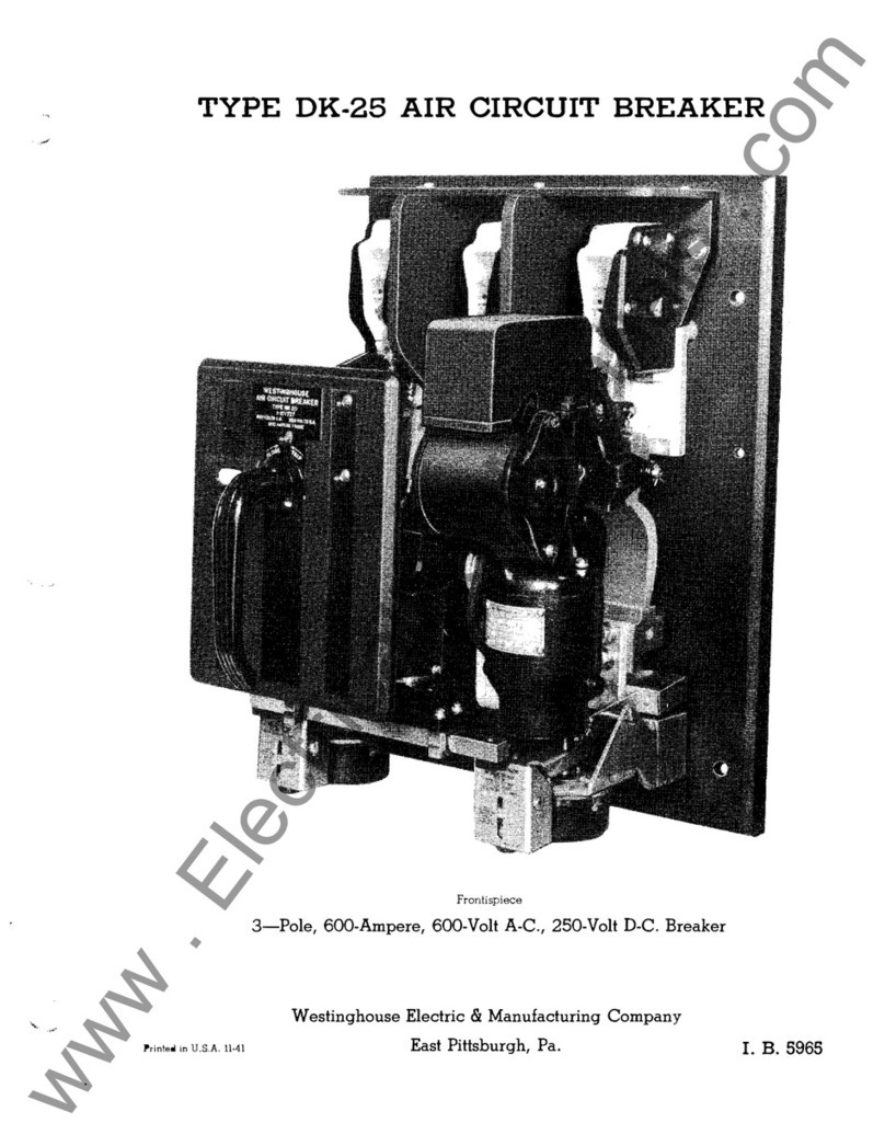
Popular Circuit Breaker manuals by other brands

IEK VA47-100 Operation manual

IEK

IEK VA47-100 Operation manual

Calira Sealine Panel 110 installation instructions

Calira

Calira Sealine Panel 110 installation instructions

Telect 009-7000-0104 installation guide

Telect

Telect 009-7000-0104 installation guide

INVT DBU-055-2 Operation manual

INVT

INVT DBU-055-2 Operation manual

Eaton NZM3-XS-L Instruction leaflet

Eaton

Eaton NZM3-XS-L Instruction leaflet

Leviton LL630 installation instructions

Leviton

Leviton LL630 installation instructions

Siemens 3KL5040 operating instructions

Siemens

Siemens 3KL5040 operating instructions

Siemens 3WX3647-5JE00 operating instructions

Siemens

Siemens 3WX3647-5JE00 operating instructions

Huanyu HUM8L Series Installation and operation instruction

Huanyu

Huanyu HUM8L Series Installation and operation instruction

Siemens 3AH4 operating instructions

Siemens

Siemens 3AH4 operating instructions

GE AM-4.16-250-9 instructions

GE

GE AM-4.16-250-9 instructions

OEZ AFD-16-1N Series Instructions for use

OEZ

OEZ AFD-16-1N Series Instructions for use

LEGRAND TX3 6000 A manual

LEGRAND

LEGRAND TX3 6000 A manual

GE Spectra Series installation instructions

GE

GE Spectra Series installation instructions

GE MicroVersaTrip AKR-75 Installation instruction

GE

GE MicroVersaTrip AKR-75 Installation instruction

ADB Safegate SCO instruction manual

ADB Safegate

ADB Safegate SCO instruction manual

Cutler-Hammer Digitrip RMS 610 instructions

Cutler-Hammer

Cutler-Hammer Digitrip RMS 610 instructions

Eaton CN13GN0 Instruction leaflet

Eaton

Eaton CN13GN0 Instruction leaflet

manuals.online logo
manuals.online logoBrands
  • About & Mission
  • Contact us
  • Privacy Policy
  • Terms and Conditions

Copyright 2025 Manuals.Online. All Rights Reserved.