5
13G264Westward Operating Instructions and Parts Manual
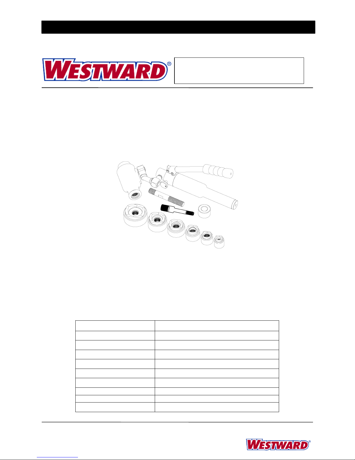
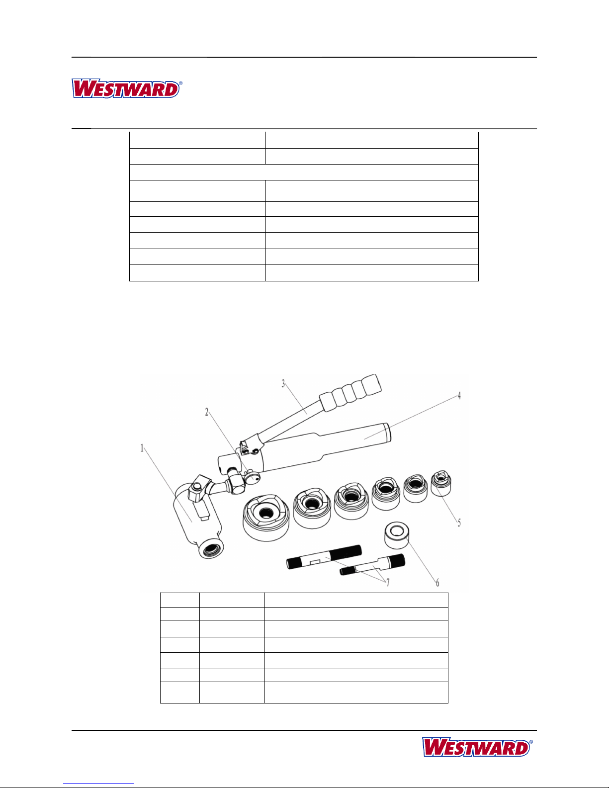
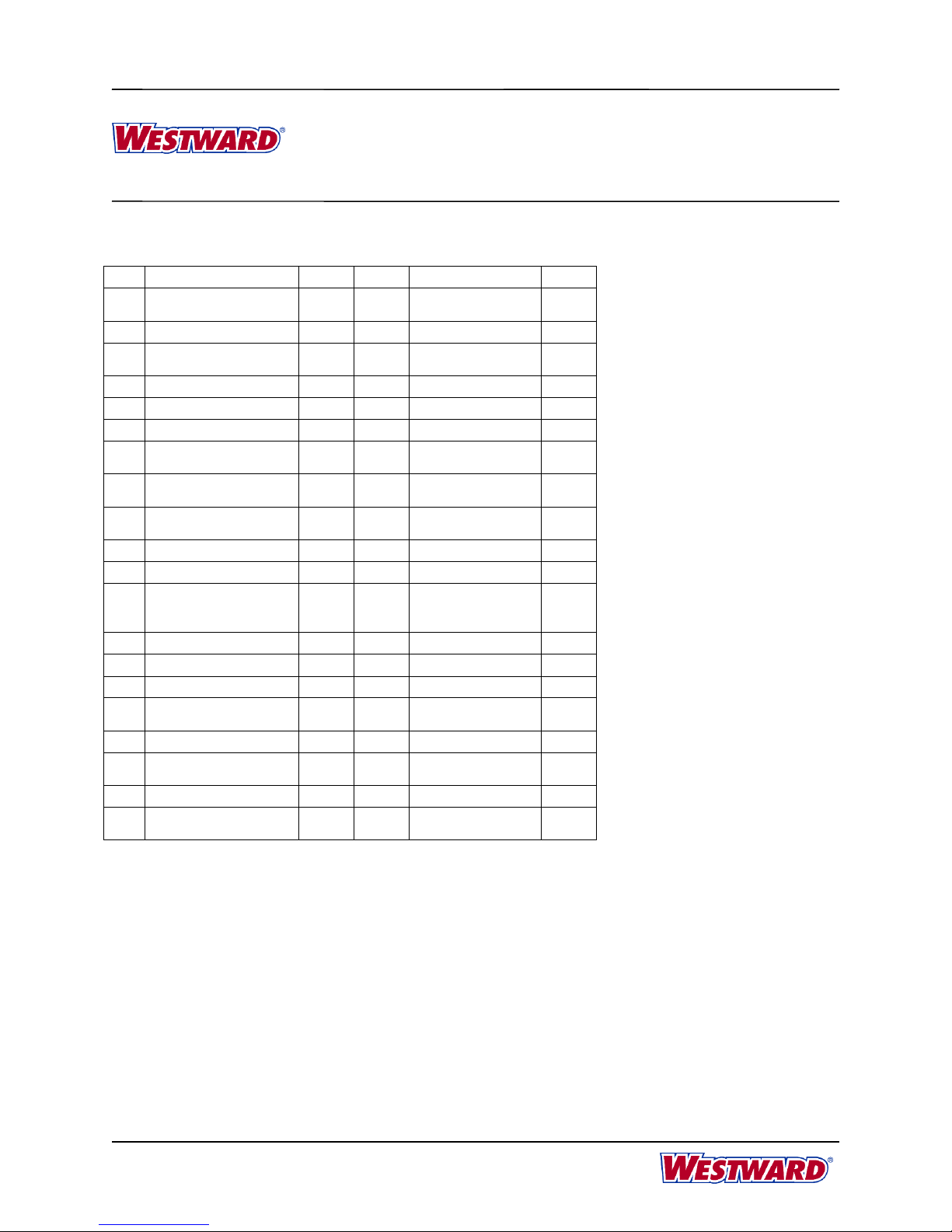
HYDRAULIC PUNCH SET, KNOCKOUT W6 PUNCH, 2
STUDS, 1 SPACER, 1 SEALING KIT
MAINTENANCE
MAINTENANCE
MAINTENANCE
MAINTENANCE AND
AND
AND
AND SERVICING
SERVICING
SERVICING
SERVICING
Damaged equipment may cause serious personal injury. Do not use damaged equipment. If
abnormal noise or vibration occurs, have the problem corrected before further using.
1. Before each using, inspect the general condition of the tool. Check for loose screws, misalignment or binding of
moving parts, cracked or broken parts, or any other condition that may affect its safe operation.
2. After using, clean external surfaces of the tool with clean, moist, smear the rust preventing oil on the metal
surface of the tool and the dies to avoid rusty. Store the tool in the dry environment.
3. Service to the tool should only be done by a qualified Service Technician.
4. After a long time using, the sealing kits will be damaged, if there is leakage please contact with the manufacturer
and/or the distributor to change the sealing kits.
Adding
Adding
Adding
Adding Hydraulic
Hydraulic
Hydraulic
Hydraulic Oil
Oil
Oil
Oila. Place the driver in a vise in a vertical position with the handles up. Unscrew the reservoir handle and remove the
bladder plug. Open the turn screw to assure the ram is fully extended.
b. Fill the rubber bladder to the point of overflow with hydraulic oil.
c. Purge air from the system: Pump the lever handle several times to remove air from the pumping chamber. Close
the turn screw until the ram completes its full travel. Repeat as necessary. Note: Open the turn screw slowly so
the ram extends slowly. Rapid return of oil and air may cause the oil to overflow the rubber bladder.
If this procedure fails to remove air, remove the bladder plug and open the turn screw. Place thumb over the plug
hole in the bladder and squeeze the bladder while pumping the lever handle several times. Close the turn screw
and pump the lever handle until the ram completes its full travel. Repeat as necessary.
d. Fill the rubber bladder to the point of overflow and replace the bladder plug. Wipe the bladder clean of excess oil
and reassemble the reservoir handle.
Oil
Oil
Oil
Oil Leaks
Leaks
Leaks
Leakse. Check for external oil leaks
f. Check that the turn screw and stem are closed tightly and seating properly.
g. Remove the reservoir handle and check for oil leaks around the rubber bladder and bladder plug.
Ram
Ram
Ram
Ram Section
Section
Section
Section Will
Will
Will
Will Not
Not
Not
Not Rotate
Rotate
Rotate
Rotateh. Loosen and readjust the set screw.
i. Hold the punch driver with the ram section down.
j. Apply a small amount of penetrating oil to the cylinder at the attachment point, and then work the ram section
back and forth.
The dust or air inside the tool will damage the sealing kit so caused the tool lose function. Make sure the
oil is clear and no dust entering into oil when changing oil. Wait for a while and exhaust the oil
completely out of the oil tube before inserting the oil plug.
Please wear the rubber gloves to avoid skin touching the oil directly, if touches it in careless, please
wash the skin by soap water in timely. In order to protect the environment please drain the waste oil to the treatment
center where was approved by government.