Wheatstone Corporation A-7000 User manual

A-7000 Audio Console
TECHNICAL MANUAL
600 Industrial Drive, New Bern, North Carolina, USA 28562

WHEATSTONE CORPORATION
600 Industrial Drive
New Bern, North Carolina 28562
tel 252-638-7000 / fax 252-637-1285
A-7000 Audio Console Technical Manual - 1st EditionA-7000 Audio Console Technical Manual - 1st Edition
A-7000 Audio Console Technical Manual - 1st Edition
©2002 Wheatstone Corporation
A-5000 / Nov 98
A-7000 / Sep 2002

Your Wheatstone A-7000 audio console is equipped with two
"module extractor tools" which are mounted in the front panel
of the console mainframe (underneath and to the right, just
behind the console’s armrest).
All modules are held into the console mainframe by two panel screws (top
and bottom) which, when removed, leave specially threaded holes that
accept the two extractor tools.
To remove a module from the mainframe:
Remove the front top and bottom module mounting screws, unscrew the
extractor tools from the mainframe, and screw each tool into a module
mounting hole. Use only four or five turns (do not over-insert; you may
damage the threaded mainframe hole underneath). Using the extractor tools
as handles, pull the module straight up out of the mainframe.
Module Removal Tools
EXTRACTOR TOOLS

page Contents – 1
A-7000 / Sep 2002
CONTENTS
A-7000 Technical Manual
Table of Contents
Chapter 1 - Installation and Power
Unpacking the Console ............................................................. 1-2
MainframeInstallation ............................................................... 1-2
System Ground .......................................................................... 1-3
Power Supplies .......................................................................... 1-4
The PSC-6008 Power Supply................................................................................. 1-5
Power Connector Pinout......................................................................................... 1-5
Failsafe Dual Redundant Supply............................................................................ 1-6
Energizing ............................................................................................................... 1-6
Audio and Control Wiring.......................................................... 1-7
The Insulation Displacement Connector System ................................................... 1-7
ConnectionProcedures .......................................................................................... 1-8
Analog Insert Points................................................................................................ 1-8
UnbalancedConnections ....................................................................................... 1-8
Wiring Procedure - Double Connection to One Pin................................................ 1-9
Chapter 2 - Mono Mic/Line Input Module
Module Overview........................................................................ 2-2
Flow Diagram.......................................................................................................... 2-2
Controls and Functions........................................................................................... 2-3
Internal Programming Options ................................................. 2-5
Mono Input Signal Routing Switches ................................................................. 2-5
Source Select ......................................................................................................... 2-5
Music/Speech Assign (PGM & AUD) ..................................................................... 2-5
Insert Bypass .......................................................................................................... 2-6
Mix-Minus Assign.................................................................................................... 2-6
Talkback Assign...................................................................................................... 2-6
IFB Assign............................................................................................................... 2-6
Mono Input Switch Controlled Logic Functions ............................................... 2-6
Axiliary Assign ........................................................................................................ 2-6
Utility Assign ........................................................................................................... 2-6
MXM/Send Assign .................................................................................................. 2-7
CUE and Solo Dropout ........................................................................................... 2-7
Mutes ...................................................................................................................... 2-7
Tally ........................................................................................................................ 2-7
Timer Restart .......................................................................................................... 2-8
Phantom Power ...................................................................................................... 2-8

page Contents – 2
A-7000 / Sep 2002
CONTENTS
Hook-ups........................................................................................2-8
AUDIO CONNECTIONS........................................................................................... 2-8
CONTROL CONNECTIONS..................................................................................... 2-9
ON & OFF Switch ..................................................................................................... 2-9
Cough ....................................................................................................................... 2-9
Talkback to Control Room ....................................................................................... 2-10
On Tally.................................................................................................................... 2-10
Off Tally.................................................................................................................... 2-10
DB Connector Pinout Drawing....................................................2-11
Chapter 3 - Stereo Line Input Module
Module Overview...........................................................................3-2
Flow Diagram............................................................................................................ 3-2
Controls and Functions............................................................................................. 3-3
Internal Programming Options ....................................................3-5
Stereo Input Signal Routing Switches ................................................................. 3-5
Music/Speech Assign ............................................................................................... 3-5
Insert Bypass ............................................................................................................ 3-5
Mix-Minus Assign...................................................................................................... 3-6
Send Mode................................................................................................................ 3-6
IFB Assign................................................................................................................. 3-6
Stereo Input Switch Controlled Logic Functions................................................ 3-6
Auxiliary Assign ........................................................................................................ 3-6
Utility Assign ............................................................................................................. 3-6
Remote ON/OFF - Start/Stop Disable ...................................................................... 3-6
External - Pulse/Constant......................................................................................... 3-7
Send Assign.............................................................................................................. 3-7
Mono Assign ............................................................................................................. 3-7
CUE and Solo Dropout ............................................................................................. 3-7
EFS (European Fader Start)..................................................................................... 3-7
Local Ready Function............................................................................................... 3-7
Mutes ........................................................................................................................ 3-7
Tally .......................................................................................................................... 3-8
Timer Restart ............................................................................................................ 3-8
Hook-ups........................................................................................3-8
AUDIO CONNECTIONS........................................................................................... 3-8
CONTROL CONNECTIONS..................................................................................... 3-9
ON & OFF Switch .................................................................................................... 3-10
On Tally.................................................................................................................... 3-10
External START & STOP ........................................................................................ 3-10
Ready....................................................................................................................... 3-11
DB Connector Pinout Drawing....................................................3-12
page Contents – 3
A-7000 / Sep 2002
CONTENTS
Chapter 4 - Output Modules
Module Overview...........................................................................4-2
Flow Diagram............................................................................................................ 4-2
Internal Programming Options ....................................................4-3
Music Insert Bypass.................................................................................................. 4-3
Speech Insert Bypass............................................................................................... 4-3
Bus-Minus Assign ..................................................................................................... 4-3
Hook-ups........................................................................................4-3
Master Output A...................................................................................................... 4-3
Audio Outputs ........................................................................................................... 4-3
Program Insert Points............................................................................................... 4-4
Master Output B...................................................................................................... 4-5
Audio Outputs ........................................................................................................... 4-5
Audition Insert Points................................................................................................ 4-6
DB Connector Pinout Drawing
Master A.................................................................................................................... 4-7
Master B.................................................................................................................... 4-8
Chapter 5 - Control Room Module
Module Overview...........................................................................5-2
Flow Diagram............................................................................................................ 5-2
Controls and Functions............................................................................................. 5-3
Internal Programming Options ....................................................5-4
Hook-ups........................................................................................5-5
Upper DB-25 Connector — AUDIO.......................................................................... 5-5
Lower DB-25 Connector — AUDIO.......................................................................... 5-5
DB-9 Connector — CONTROL................................................................................. 5-6
DB Connector Pinout Drawing.....................................................5-7
Chapter 6 - Studio Control Module
Module Overview...........................................................................6-2
Flow Diagram............................................................................................................ 6-2
Controls and Functions............................................................................................. 6-3
Internal Programming Options ....................................................6-3
Hook-ups........................................................................................6-4
Upper DB-25 Connector — AUDIO OUTPUTS........................................................ 6-4
Lower DB-25 Connector — AUDIO INPUTS............................................................ 6-4
DB-9 Connector — TALKBACK ............................................................................... 6-5
DB Connector Pinout Drawing.....................................................6-6

page Contents – 4
A-7000 / Sep 2002
CONTENTS
Chapter 7 - Meter Output Module
Module Overview...........................................................................7-2
Flow Diagram............................................................................................................ 7-2
Internal Programming Options ....................................................7-3
Hook-ups........................................................................................7-3
DB Connector Pinout Drawing.....................................................7-4
Chapter 8 - Superphone Input Module
Module Overview...........................................................................8-2
Flow Diagram............................................................................................................ 8-2
Controls and Functions............................................................................................. 8-3
Internal Programming Options ....................................................8-3
Cue Dropout.............................................................................................................. 8-3
AUX Enable .............................................................................................................. 8-3
UTL Enable ............................................................................................................... 8-3
Mics to Assign........................................................................................................... 8-4
Output Assign ........................................................................................................... 8-4
Mutes ........................................................................................................................ 8-4
On-Air Tally............................................................................................................... 8-4
Cue Enable ............................................................................................................... 8-4
Timer Restart ............................................................................................................ 8-4
Hook-ups........................................................................................8-5
Upper DB-25 Connector—Audio Inputs ................................................................... 8-5
Lower DB-25 Connector—Audio Outputs ................................................................ 8-5
Lower DB-25 Connector—Control Connections ...................................................... 8-6
DB Connector Pinout Drawing.....................................................8-7
Chapter 9 - Line Preselector Module
Module Overview...........................................................................9-2
Flow Diagram............................................................................................................ 9-2
Internal Programming Options ....................................................9-3
Hook-ups........................................................................................9-3
Upper DB-25 Connector—Audio Inputs 1-4............................................................. 9-3
Lower DB-25 Connector—Audio Inputs 5-8............................................................. 9-3
DB-9 Connector—Audio Outputs ............................................................................. 9-4
DB Connector Pinout Drawing.....................................................9-5
Chapter 10 - Tape Remote Module
Module Overview..........................................................................10-2
DB Connector Pinout Drawing
Full-FunctionControl ............................................................................................... 10-3
START/STOP Function Control............................................................................... 10-4

page Contents – 5
A-7000 / Sep 2002
CONTENTS
Chapter 11 - Meterbridge
Overview .......................................................................................11-2
Digital Timer .................................................................................11-2
Console Clock ..............................................................................11-2
Controls.................................................................................................................... 11-3
Setting the Time....................................................................................................... 11-3
Capacitor Backup .................................................................................................... 11-3
Operational Modes .................................................................................................. 11-3
Chapter 12 - Parts List
ML-7000A Mono Input Module ................................................................................ 12-2
ML-7000CA Mono Input Module.............................................................................. 12-3
ML-7000AF (w/EQ) Mono Input Module.................................................................. 12-4
ML-7000 Main PCB ................................................................................................. 12-6
SL-7000B Stereo Input Module ............................................................................... 12-8
SL-7000BZ Stereo Input Module............................................................................. 12-9
SL-7000BN (w/EQ) Stereo Input Module ............................................................... 12-10
SL-7000 Main PCB ................................................................................................. 12-12
OM-7000/A Master A Module ................................................................................. 12-14
OM-7000/B Master B Module ................................................................................. 12-16
CR-7000 Control Room Module ............................................................................. 12-18
SC-7000 Studio Control Module............................................................................. 12-21
SS-7000 Source Select (used for CR & SC modules) ........................................... 12-24
MO-7000 Meter Output Module.............................................................................. 12-25
SPN-7000 Superphone Module.............................................................................. 12-27
SL1X-6000 Loaded Card........................................................................................ 12-30
SPH2X-6000 Loaded Card..................................................................................... 12-31
LS-7000 Line Selector ............................................................................................ 12-32
TR-7000/FF Tape Remote ..................................................................................... 12-33
TR-7000/SS Tape Remote ..................................................................................... 12-34
CLK-70 Clock.......................................................................................................... 12-35
CLD-70 Clock Display............................................................................................. 12-37
PSC-6008 Power Supply........................................................................................ 12-38
LED-1 Loaded Card................................................................................................ 12-40
A7000-42 Frame..................................................................................................... 12-41
A7000-36 Frame..................................................................................................... 12-43
A7000-32 Frame..................................................................................................... 12-45
A7000-28 Frame..................................................................................................... 12-47
A7000-25 Frame..................................................................................................... 12-49
A-7000 Console ...................................................................................................... 12-51
A-7000 Spare Parts Kit........................................................................................... 12-52

page Contents – 6
A-7000 / Sep 2002
CONTENTS
Chapter 13 - Schematic Drawings
Mono Mic Input
ML-7000 Module Schematic.................................................................................... 13-3
ML-7000 Module Load Sheet .................................................................................. 13-8
MLE-7000 Module w/EQ Schematic ....................................................................... 13-9
MLE-7000 Module w/EQ Load Sheet..................................................................... 13-10
IPS-7000 Switch Card Schematic .......................................................................... 13-11
IPS-7000 Switch Card Load Sheet......................................................................... 13-12
EQ/IPS-7000 Switch Card Schematic .................................................................... 13-13
EQ/IPS-7000 Switch Card Load Sheet .................................................................. 13-14
SW2-700 Switch Card Schematic .......................................................................... 13-15
SW2-700 Switch Card Load Sheet......................................................................... 13-16
Stereo Line Input
SL-7000 Module Schematic ................................................................................... 13-17
SL-7000 Module Load Sheet.................................................................................. 13-22
SLE-7000 Module w/EQ Schematic ....................................................................... 13-23
SLE-7000 Module w/EQ Load Sheet ..................................................................... 13-24
EQ/S/IPS-7000 Switch Card Schematic................................................................. 13-25
EQ/S/IPS-7000 Switch Card Load Sheet ............................................................... 13-26
IPS-7000 & SW2-700 Schematics and Load Sheets see pages
13-11, 13-12, 13-15 & 13-16
Output Master
OM-7000 Module Schematic .................................................................................. 13-27
OM-7000 Module Load Sheet ................................................................................ 13-29
Control Room
CR-7000 Module Schematic................................................................................... 13-30
CR-7000 Module Load Sheet ................................................................................. 13-35
SPS-7000 Switch Card Schematic......................................................................... 13-36
SPS-7000 Switch Card Load Sheet ....................................................................... 13-37
SS-7000 Source Select Schematic ........................................................................ 13-38
SS-7000 Source Select Load Sheet....................................................................... 13-39
SW1-700 Switch Card Schematic .......................................................................... 13-40
SW1-700 Switch Card Load Sheet......................................................................... 13-41
Studio Control
SC-7000 Module Schematic................................................................................... 13-42
SC-7000 Module Load Sheet ................................................................................. 13-44
MMS-7000 Switch Card Schematic........................................................................ 13-45
MMS-7000 Switch Card Load Sheet ...................................................................... 13-46
SS-7000 & SW1-700 Schematics and Load Sheets see pages 13-38 - 13-41
Meter Output
MO-7000 Module Schematic .................................................................................. 13-47
MO-7000 Module Load Sheet ................................................................................ 13-49
UTS-7000 Switch Card Schematic......................................................................... 13-50
UTS-7000 Switch Card Load Sheet ....................................................................... 13-51
MMS-7000 Schematic and Load Sheet see pages 13-45 & 13-46
Superphone
SPN-7000 Module Schematic ................................................................................ 13-52
SPN-7000 Module Load Sheet............................................................................... 13-54

page Contents – 7
A-7000 / Sep 2002
CONTENTS
SPH2X-7000 Superphone Module Fix Card Schematic ........................................ 13-55
SPH2X-7000 Superphone Module Fix Card Load Sheet....................................... 13-56
SL1X-7000 Stereo Line Module Fix Card Schematic ............................................ 13-57
SL1X-7000 Stereo Line Module Fix Card Load Sheet........................................... 13-58
SPS-7000 Schematic and Load Sheet see pages 13-36 & 13-37
Line Select
LS-7000 Module Schematic ................................................................................... 13-59
LS-7000 Module Load Sheet.................................................................................. 13-61
Tape Remote
TR-7000 Module Schematic ................................................................................... 13-62
TR-7000 Module Load Sheet ................................................................................. 13-63
Clock/Timer(CLK-70)
Schematic ............................................................................................................... 13-64
Load Sheet.............................................................................................................. 13-65
Clock/Timer Display (CLD-70)
Schematic ............................................................................................................... 13-66
Load Sheet.............................................................................................................. 13-67
Power Supply
PSC-6008 Schematic ............................................................................................. 13-68
PSC-6008 Load Sheet............................................................................................ 13-69
PSR-1000 Schematic ............................................................................................. 13-70
PSR-1000 Load Sheet............................................................................................ 13-71
BRA1 Schematic..................................................................................................... 13-72
BRA1 Load Sheet ................................................................................................... 13-73
FSI-2 Schematic ..................................................................................................... 13-74
FSI-2 Load Sheet.................................................................................................... 13-75
LED-1 Schematic.................................................................................................... 13-76
LED-1 Load Sheet .................................................................................................. 13-77
Main Interface PCB
MB-6000 Load Sheet.............................................................................................. 13-78
Appendix
Balanced versus Unbalanced Input/Output Connections........ A-2
Level Measurement...................................................................... A-3
Troubleshooting........................................................................... A-4
Basic Procedure ....................................................................................................... A-4
Testing a “Live” Console - Precautions .................................................................... A-4
Integrated Circuits..................................................................................................... A-4
Other Details................................................................................. A-5

INSTALLATION and POWER
page 1 – 1
A-7000 / Sep 2002
Installation and Power
Chapter Contents
Unpacking the Console ............................................................. 1-2
MainframeInstallation ............................................................... 1-2
System Ground .......................................................................... 1-3
Power Supplies .......................................................................... 1-4
The PSC-6008 Power Supply................................................................................. 1-5
Power Connector Pinout......................................................................................... 1-5
Failsafe Dual Redundant Supply............................................................................ 1-6
Energizing ............................................................................................................... 1-6
Audio and Control Wiring.......................................................... 1-7
The Insulation Displacement Connector System ................................................... 1-7
ConnectionProcedures .......................................................................................... 1-8
Analog Insert Points................................................................................................ 1-8
UnbalancedConnections ....................................................................................... 1-8
Wiring Procedure - Double Connection to One Pin................................................ 1-9

I N S T A L L A T I O N a nd P OWER
page 1 – 2
A-7000 / Sep 2002
Installation and Power
Unpacking the Console
The console is normally shipped as two packages. One contains the
console; the other contains the rackmount power supply, connecting cable,
installation kit, spare parts kit and documentation. Begin by unpacking and
locating these items.
Do not connect the A-7000 console to its power supply (and do not
connect the power supply to the AC power line) until instructed to do
so.
MainframeInstallation
The console is designed for simple drop-through installation in a
countertop. Cut-out dimensions (in inches) for the various mainframe
types are shown on the chart below:
Console placement should take into consideration avoiding proximity
to any electromagnetic fields, such as large power transformers, motors,
and flourescent lighting fixtures.
Before proceeding with input/output connections, it will be necessary
to ground the console properly (next section).
TOTAL MAINFRAME
POSITIONS 25 28 32 36 42
DIMENSIONS
OVERALL CONSOLE 24 x 40-3/4 24 x 45-1/4 24 x 51-5/16 24 x 57-5/16 24 x 66-5/16
CUT-OUT DIMENSIONS 21-5/8 x 39-1/16 21-5/8 x 43-5/8 21-5/8 x 49-5/8 21-5/8 x 55-11/16 21-5/8 x 64-3/4
MAXIMUM NUMBER
OF INPUT MODULES 21 24 28 32 38

INSTALLATION and POWER
page 1 – 3
A-7000 / Sep 2002
CONSOLE
2-TRACK
MULTI-TRACK
AC BREAKER
BOX
DEVICE 1
DEVICE 2
DEVICE N
CONSOLE POWER SUPPLY
CONTROL ROOM POWER AMP
STUDIO POWER AMP
OTHER
POWER COMPANY
EARTH GROUND
HEAVY
(#4 or #6)
COPPER
WIRE
HIGH POWER
EQUIPMENT RACK
COPPER ROD
SOIL 3-wire ground or separate wire run from chassis
EFFECTS RACK
MIC PANEL
GND
TYPICAL SYSTEM
GROUNDING SCHEME
etc.
3–5 ft.
Tie the console ground lug
terminal strip to the system
earthground. Tieeverypiece
of equipment in the entire
audio system to the console
ground lug terminal strip.
System Ground
The first step is to ground the console.
Note that as supplied from the factory, console rackmount power
supply common, audio ground, and the A-7000 mainframe are con-
nected together at the console, but are NOT connected to electrical
ground and the chassis of the power supply. Safety requirements
dictate that a positive connection from the console mainframe to
electricalgroundbemadeinthecompletedinstallation.Useoneofthe
grounding lugs on the bottom of the mainframe to establish your
system ground. The grounding lug terminal strip may be found at the
rearoftheconsole,alongthebottomedgeofthemainframepandirectly
undertherightmostmainframeslots(tothelowerleftifyouarelooking
at the rear of the console).
The system ground serves two important purposes:
(1) It provides a zero signal reference point for the entire audio system;
(2) It assures safety from electrical shock.
Thereexisttwotermsthatoneencountersinadiscussionofground:
(A)EARTHGROUND,whichisusuallyaheavycopperroddrivenintothe
soiladjacenttothebuilding(around6feetdown)oraconnectiontothecopper
water pipes leading into the building. Either is acceptable (unless, of course,
the water pipe is made of plastic).

INSTALLATION and POWER
page 1 – 4
A-7000 / Sep 2002
(B) THE POWER COMPANY EARTH CONDUCTOR that enters the build-
ing at the power line breaker box; this conductor should be (and is often by code)
tiedto theabove-mentioned earthground atonepoint. Thispointis theSYSTEM
EARTH GROUND.
TIE THE CONSOLE GROUND LUG TERMINAL STRIP TO THE
SYSTEMEARTHGROUND. TIEEVERYPIECEOFEQUIPMENTIN
THE ENTIRE AUDIO SYSTEM TO THE CONSOLE GROUND LUG
TERMINAL STRIP. If the system earth ground point is inaccessible, tie
the console ground terminal strip to the power company earth conductor
at the main breaker box (see drawing "Typical Grounding Scheme" on
previous page).
Each piece of equipment should be connected by its own ground wire
(usually the round third pin on the AC cord). This means that every AC
outlet must have a separate conductor run to the console ground lug
terminal strip; the outlets cannot be daisy-chained as is normally encoun-
tered in commercial and residential AC systems. Any equipment not
supplied with 3-wire AC cables must have individual ground wires (16
gauge or larger) connected to their chassis grounds and then run to the
console ground lug terminal strip.
Further Grounding Details
Check all equipment to be absolutely certain that each unit is power
transformer isolated from the AC mains to prevent safety hazards.
It is assumed that in each piece of audio equipment the audio ground
and the chassis are tied together at some point. Any piece of equipment
lacking a grounded chassis is likely to be prone to interference problems.
Locateall unbalancedaudioequipmentinthesamerack ifpossible,to
minimize chassis ground potential differences. It may also be helpful to
insulateeachpieceofunbalancedequipmentfromitsmountingrailsinthe
rackbymeansofnylon10-32screwsandinsulatingwashersbetweenrails
and faceplates.
Once the system is properly grounded, proceed with the console
power supply installation and connection (next section).
Power Supplies
The A-7000 console is powered by a Wheatstone Model PSC-6008
rackmountpowersupply.Thisheavydutyunitoccupiesfive19”widerack
spaces(totalheight8-3/4”).Convectioncooled,itrequiresampleventila-
tionspaceaboveandbelowit. ThePSC-6008generatesalotofheatinthe
course of normal operation — do not mount heat sensitive devices in the
same rack cabinet.
Iffailsaferedundantsup-
plieshavebeenordered,
you will be installing two
units.

INSTALLATION and POWER
page 1 – 5
A-7000 / Sep 2002
Note the power supply (supplies) should be mounted in an equipment
rack within fifteen feet of the console (but no closer than 3 feet). Avoid
locatinganyhighgainequipment(suchasphonopreamps,taperecorders,
etc.) too near the rackmount supplies, to avoid magnetic interference into
that equipment.
Oncethe supplyisrackmounted, itshouldbeconnectedtotheconsole
usingthefactorysuppliedcable.Theconsole’stwopowersupplyconnec-
torsarelocatedattherearoftheconsole,oneateachendofthemainframe
bottompan.Ifyouareusingtwosupplies(failsafeoption)onesupplywill
connect to each console connector; otherwise only one connector will be
used(itdoesnotmatterwhichone).Notethatthepowersupplycable’s10-
pinfemaleconnectorhastoberotateduntilitslocatingpinsmatchthemale
connectors on the console. Do not force a connector on; it attaches easily
whenproperlyaligned.Connectthecable(s)firsttotheconsole,thentothe
rear of the rackmount power supply.
Note each power supply is fitted with a 3-wire grounded AC cord that
should be plugged into a "clean" AC power source, that is, an AC source
that feeds only the control room audio gear. This source should be a
separatefeedfromthosepoweringlighting,air-conditioning,oranyother
non-audio machinery. The third pin ground wire of the AC source should
be tied to the central system ground point. Note that while the AC power
cord ground wire terminates at the power supply chassis, it does NOT
connect to the A-7000 console common; the console itself must be
grounded separately. (See previous section,"System Ground".)
The PSC-6008 Power Supply
TYPICAL POWER
CONNECTOR
(10-pin)
The power feed recom-
mended in the text is of-
teninstalledandreferred
to in studios as an “iso-
lated AC ground” outlet.
It is usually orange in
color.
HA
ED
I
JB
C
G
F
A :
B :
C :
D :
E :
F :
G :
H :
I :
J :
audio/phantom common
+V audio
–V audio
lamp common
+phantom power
digital common
+digital
+lamp
n/c
n/c
–
Model PSC- D600 Power Supply
+D1 +VPHANT +D2 -V
+D LAMP+VPHANT –V
Model PSC-6008 Power Su
pp
l
y
ON
OFF

INSTALLATION and POWER
page 1 – 6
A-7000 / Sep 2002
Failsafe Dual Redundant Supply
Wheatstone failsafe power supply systems use two separate rack-
mount power supplies for each piece of powered equipment. Though
eitheriscapableofrunningafullloadonitsown,infailsafeoperationboth
units run in tandem: if one fails, the other takes over, assuring uninter-
rupted operation.
In order for failsafe systems to perform as designed, always have
BOTHrackmountsuppliespoweredupandconnectedtotheirassociated
equipment.
Energizing
Assuming the A-7000 console mainframe is properly placed and
grounded, and its PSC-6008 power supply (or supplies) correctly
rackmounted and connected to the console, you may now energize the
PSC-6008rackmountpowersupplybypluggingitintotheACmainsand
turningiton,usingitsfrontpanelcircuitbreaker/switch.(Ifyouareusing
a failsafe system, turn on BOTH supplies.) The five LEDs on the power
supply front panel should light up to indicate the presence of their
respective voltages. The console's individual module switches will as-
sume factory default settings.
Once you have verified proper power-up, turn off the rackmount powerOnce you have verified proper power-up, turn off the rackmount power
Once you have verified proper power-up, turn off the rackmount power
suppliestode-energize the console.Youmaynow proceed towireupaudiosuppliesto de-energizetheconsole.Youmay nowproceed towireupaudio
suppliestode-energize the console.Youmaynow proceed towireupaudio
and control connections.and control connections.
and control connections.
A-7000 / Feb 2003

INSTALLATION and POWER
page 1 – 7
A-7000 / Sep 2002
The AMP tool insulation dis-
placementconnectorsystem.
Notetherightanglehoodwith
self-locking tabs. The tool,
multipinconnectors(withgold
plated pins) and latching
hoodsaresupplied with each
console.
Audio and Control Wiring
All audio and control I/O connections to the A-7000 console are made
through multipin connectors (DB-25 and DB-9) located on the bottom of the
console mainframe.
The Insulation Displacement Connector System
The I/O wiring interface system is based on insulation displacement
technology. A special AMP wiring tool is included with each console; it is
auto-indexing, and allows individual wire connections to be positively made
with a single squeeze of the tool's trigger. The trigger action is ratchet
controlled, and will not release until a full connection is made. Once released,
the multipin connector held in the tool's jaw automatically indexes to the next
connectorpin.Thetechnologyissuchthatnostripping,solderingortinningof
wire ends is required; all that is needed is for the wires destined for the
connectorbesnub cutandlaidout inorder(althoughtubing shouldbeusedon
baredrainwires).AnemptyDB-25orDB-9connectorisinsertedintothetool,
indexed to the first pin, and the wires are inserted one by one into the jaw and
thetriggersqueezed.Inthiswayasinglemultipinconnectorcanbecompletely
wired up in a minute or two.
In the event of a wiring error, connector pins may easily be removed from
the shell with the wire still attached, and inserted into the correct position.
Observethesideoftheconnector,withthemetalpartdown.Youwillseearow
of"Vees"—simplypressthetopoftheveetogetherwithascribeorothersharp
instrument; this will unlock the pin from the shell, and it can be removed and
insertedintothecorrectposition.Spreadtheveeaparttolockthepininthenew
position. It should never be necessary to discard a connector due to a wiring
error.
Note that mating hoods for each connector are also supplied with the
console. These have locking screws that hold the connectors securely to the
bottom of the console mainframe.

INSTALLATION and POWER
page 1 – 8
A-7000 / Sep 2002
ConnectionProcedures
Assuppliedfromthefactory,theconsolerequiresnologicconnections
tofunction.Thereforeanorderlyinstallationbeginswiththeaudiowiring.
Note this manual is organized by module type (inputs, outputs, monitor
modules, etc.); each chapter contains detailed wiring instructions for its
module type. Proceed through the manual, chapter by chapter, until all
moduleshavebeenwiredtosuityourparticularinstallationrequirements.
Onceproperaudiooperationisverified,gobacktoeachindividualchapter
and proceed with control wiring.
Recommendedsetupistohaveallmicrophoneinputsconnectedtothe
first channels (mono mic type), with the remaining line input sources
connected to stereo line inputs. It is good practice to group input types
together.Forexample,ifyouhavethreecartmachines,connectthemtothe
inputs of three successive stereo line modules.
Analog Insert Points
Certain module signals have insert patch points in their signal chains
toallowoutboard audio processing.TheseincludeMONO MIC INPUTS
(MM-7000) and OUTPUT MODULES (OM-7000).
Normally these points are internally bridged at the factory (via PCB-
mounted programming switches) prior to shipment. If you intend to use
outboardsignal loopsatthesepoints,youmustreprogram theseswitches.
See pages 2-6 (mic inputs) and 4-3 (output modules) for details.
UnbalancedConnections
INPUTS — Wire to the console with typical shielded two conductor
cable(likeBelden9451),justasifyouwereconnectingabalancedsource.
Attheunbalancedsourcemachine’soutput,connecttheblackwire(LOW)
to the shield. If the machine has a -10 dBu output, don’t hesitate to turn
module input gain as high as is needed.
OUTPUTS — A-7000 consoles use a balanced output circuit which
behaves exactly like the secondary of a high-quality transformer, with no
center tap—this output is both balanced and floating. Either the HIGH or
LOWsideoftheoutputshouldbestrappedtoground,withtheoutputtaken
fromtheotherside.(Normallyyou’dstrapLOWtoground,andtakeHIGH
to feed your unbalanced equipment.)
See Appendix for a dis-
cussionofbalancedver-
susunbalancedconnec-
tions.

INSTALLATION and POWER
page 1 – 9
A-7000 / Sep 2002
Wiring Procedure - Double Connection to One Pin
ref: DB-25 male multi-pin connector
Most audio equipment machine interfaces (as well as Wheatstone consoles) use
subminiature D-type connectors. Sometimes the interfaces require making two connec-
tions to a single DB pin. If the wiring has been set up using punchblocks, this is not a
problem; however, for situations where direct machine-to-console wiring is used, Wheat-
stone recommends the following procedure:
1) Connect the first wire to the desired pin as you normally would.
2) Note connector pins may easily be removed from the DB-25 shell with the wire still
attached: Hold the connector with the metal part down and observe its side. You
will see a row of "Vees"—simply press the top of the selected vee together with a
scribe or other sharp instrument; this will unlock the pin from the shell, allowing
it to be removed.
3) With the pin removed, strip out a short section of insulation from the connected
wire and wrap and solder the second wire to the first as shown above.
4) A short piece of heatshrink tubing (pictured here before being slid into place)
completes the connection.
5) Re-insert the pin into the DB-25 shell, spreading the vee apart to lock it in place.

page 2 – 1
A-7000 / Sep 2002
MONO MIC/LINE INPUT MODULE
Mono Mic/Line Input
Module (ML-7000)
Chapter Contents
Module Overview........................................................................ 2-2
Flow Diagram.......................................................................................................... 2-2
Controls and Functions........................................................................................... 2-3
Internal Programming Options ................................................. 2-5
Mono Input Signal Routing Switches ................................................................. 2-5
Source Select ......................................................................................................... 2-5
Music/Speech Assign (PGM & AUD) ..................................................................... 2-5
Insert Bypass .......................................................................................................... 2-6
Mix-Minus Assign.................................................................................................... 2-6
Talkback Assign...................................................................................................... 2-6
IFB Assign............................................................................................................... 2-6
Mono Input Switch Controlled Logic Functions ............................................... 2-6
Axiliary Assign ........................................................................................................ 2-6
Utility Assign ........................................................................................................... 2-6
MXM/Send Assign .................................................................................................. 2-7
CUE and Solo Dropout ........................................................................................... 2-7
Mutes ...................................................................................................................... 2-7
Tally ........................................................................................................................ 2-7
Timer Restart .......................................................................................................... 2-8
Phantom Power ...................................................................................................... 2-8
Hook-ups..................................................................................... 2-8
AUDIO CONNECTIONS......................................................................................... 2-8
CONTROL CONNECTIONS................................................................................... 2-9
ON & OFF Switch ................................................................................................... 2-9
Cough ..................................................................................................................... 2-9
Talkback to Control Room .................................................................................... 2-10
On Tally................................................................................................................. 2-10
Off Tally................................................................................................................. 2-10
DB Connector Pinout Drawing................................................ 2-11
Table of contents
Other Wheatstone Corporation Recording Equipment manuals

Wheatstone Corporation
Wheatstone Corporation A-5000 User manual

Wheatstone Corporation
Wheatstone Corporation D-5.1 User manual

Wheatstone Corporation
Wheatstone Corporation A-2000 User manual

Wheatstone Corporation
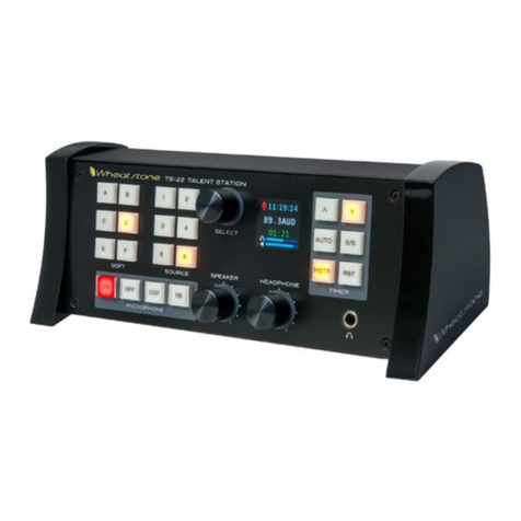
Wheatstone Corporation Talent Station TS-22 User manual

Wheatstone Corporation
Wheatstone Corporation E-4 User manual

Wheatstone Corporation
Wheatstone Corporation EMX User manual

Wheatstone Corporation
Wheatstone Corporation DMX-8 User manual

Wheatstone Corporation
Wheatstone Corporation TV-1000 User manual

Wheatstone Corporation
Wheatstone Corporation Dimension Three User manual

Wheatstone Corporation
Wheatstone Corporation D-9 User manual