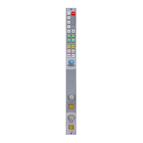
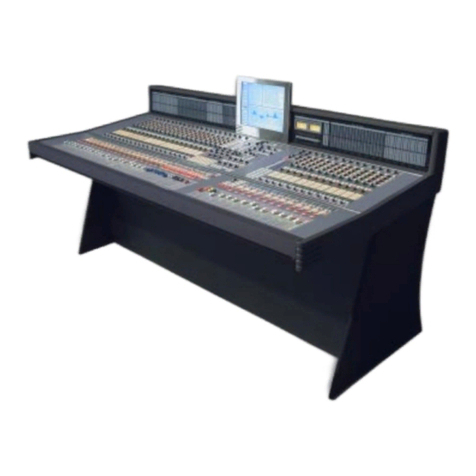
Wheatstone Corporation D-9 User manual

D-9 Digital Control Surface
TECHNICAL MANUAL
600 Industrial Drive, New Bern, North Carolina, USA 28562

WHEATSTONE CORPORATION
600 Industrial Drive
New Bern, North Carolina 28562
tel 252-638-7000 / fax 252-637-1285
D-9 Digital Control Surface Technical Manual - 1st EditionD-9 Digital Control Surface Technical Manual - 1st Edition
D-9 Digital Control Surface Technical Manual - 1st Edition
©2003 Wheatstone Corporation
D-9/Oct 2003

ATTENTION
READ ME!
D-9 / Oct 2003
Attention!
Federal Communications Commission (FCC) Compliance
Notice:
Radio Frequency Notice
NOTE: This equipment has been tested and found to comply with the
limitsforaClassAdigitaldevice,pursuanttoPart15oftheFCCrules.These
limits are designed to provide reasonable protection against harmful
interference when the equipment is operated in a commercial environment.
This equipment generates, uses, and can radiate radio frequency energy
and, if not installed and used in accordance with the instruction manual,
may cause harmfulinterference to radio communications.Operation ofthis
equipment in a residential area is likely to cause harmful interference in
which case the user will be required to correct the interference at his own
expense.
!
This is a Class A product. In a domestic environment, this
product may cause radio interference, in which case, the
user may be required to take appropriate measures.
This equipment must be installed and wired properly in order to assure
compliance with FCC regulations.
Caution! Any modifications not expressly approved in writing by
Wheatstone could void the user's authority to operate this equipment.

RR
RR
READEAD
EADEAD
EAD MM
MM
M
EE
EE
E!!
!!
!
May 2003
IMPORTANT!
Cleaning the Acrylic Surface
An acrylic surface is a beautiful, lustrous material that is outstanding in
durability and break resistance. With proper care, it will retain its attractive
appearanceformanyyearstocome.Thiscareshouldincludeprecautionsagainst
scratchingorcontactwithobjectsofhightemperaturethatmightmarthesurface.
A few simple precautions will preserve the beauty of the acrylic.
• FIRST be sure the surface to be cleaned is powered off.
• NEVER spray or pour any liquid directly onto the surface.
• TO AVOID scratching these surfaces, use a soft brush or cloth to gently
brushawayanylargerdirtparticles.Alternatelythelargerparticlescanbeblown
from the surface with the use of canned air.
• USE a soft, clean lint free cloth or micro fiber cloth and clean lukewarm
water to clean the surface. For stubborn dirt and stains use a mild, nonabrasive
soap and water mixture with the gentle cleaning cloth. Use only light pressure
when cleaning. Avoid rubbing dirt or grit into the surface. Turn the cloth often
andreplacewithacleanclothfrequently.Drybyblottinggentlywithaclean,dry
cloth.
• AVOID using kleenex, paper towels, sponges or other coarse shop towels,
as these materials may contain abrasives that can scratch acrylic surface.
• DO NOT USE ketones, aromatics, esters, halogens, window cleaning
sprays, alcohol, kitchen scouring compounds, or solvents (such as acetone,
benzene, gasoline, carbon tetrachloride, or thinners).
Caution! Donotuseammoniabasedcleaningsolutionsastheycancausethe
surface to yellow, and became brittle and eventually cause structural damage to
the acrylic surface.
Wheatstonewillnotbeliablefordamageresultingfromimpropercleaning
and maintenance.
!

page Contents – 1
D-9 / Oct 2003
CONTENTS
D-9 Technical Manual
Table of Contents
Chapter 1 – General Information
Introduction ...................................................................................1-2
Control Surface Placement ..........................................................1-3
Power Supply ................................................................................1-4
Failsafe Dual Redundant Supply.............................................................................. 1-5
Energizing ................................................................................................................. 1-5
I/O Connections.............................................................................1-6
The Insulation Displacement Connector System .....................................................1- 6
Wiring Procedure - Double Connection to One Pin.................................................. 1-8
Chapter 2 - Input Panel (IS-D9)
Controls and Functions................................................................2-2
Input Sources............................................................................................................ 2-2
Gain Control.............................................................................................................. 2-3
Phantom Power ........................................................................................................ 2-3
AUX........................................................................................................................... 2-3
Mode Selector Indicator............................................................................................ 2-3
Pan/Balance Knob .................................................................................................... 2-3
Bus Minus ................................................................................................................. 2-4
Dynamics and EQ..................................................................................................... 2-4
Main Bus Assign ....................................................................................................... 2-4
Output Assign Displays ............................................................................................ 2-4
SET Button................................................................................................................ 2-5
Page Button .............................................................................................................. 2-5
DCM Displays ........................................................................................................... 2-5
PFL (Cue) Switch...................................................................................................... 2-6
AFL (Solo) Switch ..................................................................................................... 2-6
Channel ON Switches............................................................................................... 2-6
Fader......................................................................................................................... 2-6
LCD Display .............................................................................................................. 2-6
Input Level ........................................................................................................... 2-7
Selected Source .................................................................................................. 2-7
Preset Source ...................................................................................................... 2-7
Channel Status .................................................................................................... 2-7
Channel Number.................................................................................................. 2-7

page Contents – 2
D-9 / Oct 2003
CONTENTS
Chapter 3 - Control Panel (EFS-D9)
Controls and Functions............................................................. 3-2
Monitors .................................................................................................................. 3-2
Control Room Section ....................................................................................... 3-3
Studio Section.................................................................................................... 3-4
Headphone Section ........................................................................................... 3-4
Mode Control and Indicators ............................................................................. 3-5
Bus-Assign Section................................................................................................. 3-5
Surround/PAN System............................................................................................ 3-5
Solo(AFL)/MUTE/DIM/Cue(PFL)Section............................................................... 3-6
Clear AFL/PFL ........................................................................................................ 3-7
Switched Meters Section ........................................................................................ 3-7
Mode Select Section............................................................................................... 3-7
AUX/MXM Master Outputs ..................................................................................... 3-8
MIX-MINUS Assign................................................................................................. 3-8
DCM Assign ............................................................................................................ 3-8
Copy Section .......................................................................................................... 3-8
To Copy Groups ................................................................................................ 3-9
To Copy One and Paste Many .......................................................................... 3-9
To Copy One To All ......................................................................................... 3-10
Test Section .......................................................................................................... 3-10
Timer Section........................................................................................................ 3-10
Time of Day Clock ................................................................................................ 3-11
XY Controller Section ........................................................................................... 3-11
Selecting Input Channel Sources .................................................................... 3-11
Selecting Output Mix Destinations .................................................................. 3-11
Changing Output Mix Destinations.................................................................. 3-12
Removing Output Mix Destinations ................................................................. 3-12
X-Y Set Button ................................................................................................. 3-12
Event Controller Section....................................................................................... 3-11
Storing an Event .............................................................................................. 3-12
Taking an Event............................................................................................... 3-13
Undoing an Event ............................................................................................ 3-13
Modifying the Currently Selected Event .......................................................... 3-13
Deleting an Event ............................................................................................ 3-13
Previewing an Event ........................................................................................ 3-13
Event Default Button........................................................................................ 3-14
Establishing the Default Setting ...................................................................... 3-14
Naming an Event ............................................................................................. 3-14
Control Modes ................................................................................................. 3-14
EQ Section............................................................................................................ 3-15
High-Pass Filter ............................................................................................... 3-15
Low-Pass Filter ................................................................................................ 3-15
Equalizer .......................................................................................................... 3-16
Phase............................................................................................................... 3-16
Function Lock ....................................................................................................... 3-16
D-9 / Jan 2006
page Contents – 3
D-9 / Oct 2003
CONTENTS
Chapter 4 - Master Panel (MFS-D9)
Controls and Functions................................................................4-2
Master Program Outputs .......................................................................................... 4-2
Mix Destination 5.1 Surround .............................................................................. 4-2
Master Mix Destinations ...................................................................................... 4-3
Channel Master ON/OFF..................................................................................... 4-3
Dyn....................................................................................................................... 4-3
EQ ........................................................................................................................ 4-3
DCM Master Displays .......................................................................................... 4-4
PFL (Cue) ............................................................................................................ 4-4
AFL (Solo)............................................................................................................ 4-4
Master Faders...................................................................................................... 4-4
Submixes (Groups) Outputs ..................................................................................... 4-5
TB ........................................................................................................................ 4-5
Output Destinations, Group 1 Example............................................................... 4-5
Groups Output Display ........................................................................................ 4-5
DCM Group Displays ........................................................................................... 4-5
ON (G1-G8) Switch ............................................................................................. 4-6
PFL (Cue) ............................................................................................................ 4-6
AFL (Solo)............................................................................................................ 4-6
Submix (Group) Faders ....................................................................................... 4-6
Page Buttons ............................................................................................................ 4-6
Chapter 5 - Dynamics Processing Control Panel (DCM-D9)
Controls and Functions................................................................5-2
Compressor/Limiter .................................................................................................. 5-2
Dyn In................................................................................................................... 5-3
Threshold ............................................................................................................. 5-3
Attack ................................................................................................................... 5-3
Ratio..................................................................................................................... 5-4
Release................................................................................................................ 5-4
Makeup Gain ....................................................................................................... 5-4
MXM Confidence Feed ............................................................................................. 5-4
Talkback Preselects.................................................................................................. 5-5
Display Buttons......................................................................................................... 5-6
Programmable Buttons ............................................................................................. 5-6
Mute Groups ............................................................................................................. 5-7
Fader......................................................................................................................... 5-7
Chapter 6 - Host CPU (HC-9)
Overview ........................................................................................6-2
HC-9 BIOS Settings/Format..........................................................6-2
Ethernet IP Addressing ................................................................6-2
Ethernet Interface Wiring .............................................................6-2
Mixer Link Wiring ..........................................................................6-3
Internal Programming Options ....................................................6-3
D-9 / Jan 2006

page Contents – 4
D-9 / Oct 2003
CONTENTS
Switch Settings .............................................................................6-3
SW5-SW8 - CAT5 vs. Fiber & Transceiver Select ................................................... 6-3
SW10 - Master Reset ............................................................................................... 6-3
SW11 - CPU Reset................................................................................................... 6-3
SW12 Position 1 - Sample Rate ............................................................................... 6-3
SW12 Position 3 - Redundant CPU ......................................................................... 6-4
SW12 Position 4 - CAT5 vs. Fiber............................................................................ 6-4
Hook-Ups .......................................................................................6-4
“ETH A” RJ-45 - Main Ethernet Connector .............................................................. 6-4
“ETH B” RJ-45 - Optional Redundant Computer Ethernet Connector ..................... 6-4
“CAT5” RJ-45 - Mixer Link Connector ...................................................................... 6-4
Typical Ethernet Cable .................................................................6-5
Typical Crossover Cable ..............................................................6-5
Optical Fiber Interface ..................................................................6-6
Optical Transceiver................................................................................................... 6-6
Connectors Type ...................................................................................................... 6-6
Optical Fiber Cable ................................................................................................... 6-6
HC-9 Pinouts Drawing ..................................................................6-7
Chapter 7 - Schematic and Load Sheet Drawings
IP-9 4 Inputs Panel Switch Card
Schematic ................................................................................................................. 7-2
Load Sheet................................................................................................................ 7-8
IQ-9 IQ Card
Schematic ................................................................................................................. 7-9
Load Sheet............................................................................................................... 7-10
MN-9 Control Panel Switch Card
Schematic ................................................................................................................ 7-11
Load Sheet............................................................................................................... 7-16
MFS-9 Master Panel Switch Card
Schematic ................................................................................................................ 7-17
Load Sheet............................................................................................................... 7-19
IQO-9 Master Panel IQ Card
Schematic ................................................................................................................ 7-20
Load Sheet............................................................................................................... 7-22
DCM-9 DCM Panel Switch Card
Schematic ................................................................................................................ 7-23
Load Sheet............................................................................................................... 7-26
HC-9 Host Controller Card
Schematic ................................................................................................................ 7-27
Load Sheet............................................................................................................... 7-34
BP-9 Back Plane Card
Schematic ................................................................................................................ 7-35
Load Sheet............................................................................................................... 7-36
D-9 / Jul 2009
!
All devices in the
system must be
set to the same
sample rate!

page Contents – 5
D-9 / Oct 2003
C O N T E N T S
BPR-9 Back Plane Repeater Card
Schematic ................................................................................................................ 7-37
Load Sheet .............................................................................................................. 7-38
32VC5-5 +5V DC to DC Converter Card
Schematic ................................................................................................................ 7-39
Load Sheet .............................................................................................................. 7-40
VU-9 VU Receiver Card
Schematic ................................................................................................................ 7-41
Load Sheet .............................................................................................................. 7-42
SW1-700 Switch Card
Schematic ................................................................................................................ 7-43
Load Sheet .............................................................................................................. 7-44
PWI-5.1 Power Interface Card
Schematic ................................................................................................................ 7-45
Load Sheet .............................................................................................................. 7-46
Appendices
Appendix 1
Control Surface Clock ................................................................. A-3
Setting the Time........................................................................................................A-3
Update Options.........................................................................................................A-3
Synchronize .............................................................................................................. A-3
Battery Backup ......................................................................................................... A-4
Appendix 2
Options Text File .......................................................................... A-6
Introduction ............................................................................................................... A-6
Modifying The Options Text File...............................................................................A-6
A Sample Example From The File ........................................................................... A-7
A Second Example ................................................................................................... A-8
An Example File - Complete.....................................................................................A-9
Appendix 3
Replacement Parts List .............................................................. A-14
Spare Parts Kit ............................................................................ A-17
D-9 / Jan 2007

GENERAL INFORMATION
page 1 – 1
D-9 / Oct 2003
General Information
Chapter Contents
Introduction ................................................................................ 1-2
Control Surface Placement ....................................................... 1-3
Power Supply ............................................................................. 1-4
Failsafe Dual Redundant Supply............................................................................ 1-5
Energizing ............................................................................................................... 1-5
I/O Connections.......................................................................... 1-6
The Insulation Displacement Connector System .................................................. 1- 6
Wiring Procedure - Double Connection to One Pin................................................ 1-8

GENERAL INFORMATION
page 1 – 2
D-9 / Oct 2003
General Information
Introduction
TheWheatstoneD-9DigitalTelevisionAudioControlSurfaceisfullyloaded
withallthefunctionsandcontrolcapabilityneededbymosttelevisionbroadcast
facilities:5.1digitalsurround,ahostofmix-minuscleanfeedoutputs,individual
channelbus-minusoutputs,6-banddigitalequalization,digitaldynamicprocess-
ing,andintegratedroutingthatcanaccessliterallythousandsofsourcesandfeed
thousands of destinations. In addition it can be ordered with paging and
motorizedfaders,allowingyoutoget40channelsworthofmixingina20channel
footprint. The D-9 gives your operators the added convenience of eight stereo
subgroups,fourstereoauxiliarybusses,fouradditionalDCM/MUTEbusses,and
afullevent/memoryfrontpanelstorageand recallsystemthatdoesn’trequirean
external computer to operate. And because it’s a live television console, it has
extensive communication capability. If there is a mix, you can talk to it. It even
has programmable talkback buttons.
Designedtointegrateflawlesslywiththe WheatstoneBRIDGEdigitalaudio
networkrouter,theD-9controlsurface allowsyoutoeasilycreatelargeor small
platform-basedsystemsthatareexceptionallyuser-friendlyandflexible.Wheat-
stone BRIDGE network cages house all I/O ports and engine cards, and may be
wired in tandem within a single equipment room or interconnected to separate
remotelocations bymeansof fiber-opticorCAT-5 cablestoprovide singlewire
studio integration schemes.
Once configurated, the system operates entirely independently of external
computers. Configuration itself is intuitive and carried out onsite by means of
user-friendly graphic interfaces provided by Wheatstone desktop software. The
D-9 system also takes full advantage of Wheatstone’s exclusive VDip configu-
rationsoftware,so thatstudio functions(likemutes, faderand timerstarts,tally,
etc.) are easily accomplished right at your desktop. Once completed, all settings
are retained in non-volatile storage, allowing the entire system to run indepen-
dently. Ethernet protocol is built in, providing interface with automation,
scheduling, and hardware controllers as you require.

G E N E R A L I NFORMATION
page 1 – 3
D-9 / Oct 2003
Control Surface Placement
The D-9 digital audio control surface is designed for countertop mounting.
Although the rubber feet on the bottom keep the surface from being easily moved
when simply placed on the counter, holes have been provided so that screws may
be used to mount the surface securely to the countertop. Carefully remove the
appropriate panels from the frame, screw the mainframe to the counter top, and
reinstall the removed panels. The three available frame sizes dimensions (in inches)
are shown in the drawings below.
Do not connect the D-9 control surface to its power supply (and do not connect
the power supply to the AC power line) until instructed to do so.
D-9 / Jan 2006
77.380
18.355 18.780
14.500
10 HOLES, D=0.200";
USE #8 SCREWS
17.66518.780
D-9 4 BAY FRAME
58.600
14.500
17.66518.78018.355
8 HOLES, D=0.200";
USE #8 SCREWS
D-9 3 BAY FRAME
39.820
9.135
25.252
2.233
14.500
18.355 17.665
6 HOLES, D=0.200";
USE #8 SCREWS
D-9 2 BAY FRAME

GENERAL INFORMATION
page 1 – 4
D-9 / Oct 2003
Power Supply
The D-9 control surface is powered by an SPS-180, or SPS-400 power
supply installed in a Wheatstone Model PSR rackmount unit. Each PSR
housesuptofourSPS-180,oruptotwoSPS-400powersupplyunits.Mount
the power supply in a standard 19” equipment rack, keeping in mind that
adequate ventilation is necessary to prevent heat build-up within the rack.
Note the power supply (supplies) should be mounted in an equipment
rackwithinfifteenfeetofthecontrol
surface (but no closer than 3 feet).
Oncethesupplyisrackmounted,
itshould beconnected tothe control
surface using the factory supplied
cable. The cable has two different
types of connectors on it: a 5-pin
female connector that connects to
the control surface’s power supply
connector, and an 8-pin male con-
nectorthatplugsintothePSRpower
supply. The control surface’s two
powersupplyconnectorsarelocated
at the rear of the control surface, in
the middle of the meterbridge bot-
tompan.Ifyouareusingonesupply,
connect it to one of the control sur-
face connectors (it doesn’t matter
which one). If you are using the
failsafe option, connect one end of a
power supply cable to either control
surface power connector and con-
nect the other end of the cable to one
of the two power supply connectors.
Then use the other cable to connect
the second power supply connector
to the remaining control surface power supply connector. Connect the
cable(s)first tothe controlsurface,thentothe rearof therackmount power
supply.
8
7
6
5
PIN
1
2
3
4
PIN
8-pin Connector
Male
5-pin Connector
Female
Power Supply EndConsole End
4
3
2
1
5
RED, YEL
BLU, BLK
N/C
N/C
N/C
N/C
N/C
N/C
PS Cable Pinou
t
RED
YEL
BLU
BLK
N/C
+V in
-V in
Iffailsaferedundantsupplies
have been ordered, you will
be installing two SPS-180,
or SPS-400 units.
Power Supply
End
Control Surface
End
Front view of the PSR rackmount power supply
Rear view of the SPS-400 unit Rear view of the
SPS-180 unit
D-9 / Aug 2004

GENERAL INFORMATION
page 1 – 5
D-9 / Oct 2003
Note each power supply is fitted with a 3-wire grounded AC cord
that should be plugged into a "clean" AC power source, that is, an AC
sourcethatfeedsonlythecontrolroomaudiogear. Thissourceshould
be a separate feed from those powering lighting, air-conditioning, or
any other non-audio machinery. The third pin ground wire of the AC
source should be tied to the central system ground point.
Failsafe Dual Redundant Supply
Wheatstone failsafe power supply systems use two SPS-180 or
SPS-400powersuppliesforeachpieceofpoweredequipment.Though
either is capable of running a full load on its own, in failsafe operation
both units run in tandem: if one fails, the other takes over, assuring
uninterrupted operation.
In order for failsafe systems to perform as designed, always have
BOTH rackmount supplies powered up and connected to their associ-
ated equipment.
Energizing
Assuming the D-9 control surface mainframe is properly placed,
and its PSR power supply (or supplies) correctly rackmounted and
connected to the control surface, you may now energize the PSR
rackmountpowersupplybypluggingitintotheACmains.Thecontrol
surface'sLCDdisplayswillilluminateandindividualmoduleswitches
will assume factory default settings.
Note: To de-energize the control surface, unplug the rackmount
power supply’s AC cord from the AC mains. Never de-energize the
control surface by disconnecting the cable that connects the control
surface and power supply together.
Once you have verified proper power-up, unplug the rackmount powerOnce you have verified proper power-up, unplug the rackmount power
Once you have verified proper power-up, unplug the rackmount power
supplies to de-energize the control surface. You may now proceed tosupplies to de-energize the control surface. You may now proceed to
supplies to de-energize the control surface. You may now proceed to
wire up audio and control connections.wire up audio and control connections.
wire up audio and control connections.
The power feed recom-
mended in the text is of-
teninstalledandreferred
to in studios as an “iso-
lated AC ground” outlet.
It is usually orange in
color.

G E N E R A L I NFORMATION
page 1 – 6
D-9 / Oct 2003
The AMP tool insulation dis-
placement connector system.
Note the right angle hood with
self-locking tabs. The tool,
multipin connectors (with gold
plated pins) and latching
hoods are supplied with each
control surface.
I/O Connections
All user wiring to and from the D-9 control surface is made via
connectors located on the control surface’s rear panel. There are also
two RJ-45 connectors for main (ENET A) and failsafe (ENET B - only
used if the surface has a redundant CPU) ethernet connections.
CAT-5 or multi-mode optical fiber Mixer Link connections are made
via RJ-45 or LC type optical connectors. Two 5-pin male connectors
are for power supply connections. VGA connections are made via the
female DB-15 connector that is mounted next to the ENET A connec-
tor. For all wiring pinout connections refer to Chapter 6. The sketch
below shows connector locations.
The Insulation Displacement Connector System
The I/O wiring interface system is based on insulation displacement
technology. A special AMP wiring tool is included with each control
surface; it is auto-indexing, and allows individual wire connections to
be positively made with a single squeeze of the tool's trigger. The
trigger action is ratchet controlled, and will not release until a full
connection is made. Once released, the multipin connector held in the
tool's jaw automatically indexes to the next connector pin. The technol-
NOTE: Keyboard, VGA, and
COM connectors for factory
use only.
D-9 / Mar 2008
ENET A
RJ-45
ENET B
RJ-45
KEYBOARD NOT
USED
DB-9 DB-9
NOT
USED
VGA
DB-15
CAT5
FIBER
MIXER LINK
RJ-45 OPTO
POWER A POWER B NOT USED

G E N E R A L I NFORMATION
page 1 – 7
D-9 / Oct 2003
ogy is such that no stripping, soldering, or tinning of wire ends is required;
all that is needed is that the wires destined for the connector be snub cut and
laid out in order (although tubing should be used on bare drain wires). An
empty DB-9 connector is inserted into the tool, indexed to the first pin, and
the wires are inserted one by one into the jaw and the trigger squeezed. In
this way a single multipin connector can be completely wired up in a
minute or two. These connectors will accept wire gauge 22 - 26 AWG.
In the event of a wiring error, connector pins may easily be removed
from the shell with the wire still attached, and inserted into the correct
position. Observe the side of the connector, with the metal part down. You
will see a row of "Vees"—simply press the top of the vee together with a
scribe or other sharp instrument; this will unlock the pin from the shell, and
it can be removed and inserted into the correct position. Spread the vee
apart to lock the pin in the new position. It should never be necessary to
discard a connector due to a wiring error.
Note that mating hoods for each connector are also supplied with the
system. These have locking screws that hold the connectors securely to
their mates.
D-9 / Jan 2006

GENERAL INFORMATION
page 1 – 8
D-9 / Oct 2003
Wiring Procedure - Double Connection to One Pin
ref: DB-25 male multi-pin connector
Most audio equipment machine interfaces (as well as Wheatstone consoles) use
subminiature D-type connectors. Sometimes the interfaces require making two connec-
tions to a single DB pin. If the wiring has been set up using punchblocks, this is not a
problem; however, for situations where direct machine-to-console wiring is used, Wheat-
stone recommends the following procedure:
1) Connect the first wire to the desired pin as you normally would.
2) Note connector pins may easily be removed from the DB-25 shell with the wire still
attached: Hold the connector with the metal part down and observe its side. You
will see a row of "Vees"—simply press the top of the selected vee together with a
scribe or other sharp instrument; this will unlock the pin from the shell, allowing
it to be removed.
3) With the pin removed, strip out a short section of insulation from the connected
wire and wrap and solder the second wire to the first as shown above.
4) A short piece of heatshrink tubing (pictured here before being slid into place)
completes the connection.
5) Re-insert the pin into the DB-25 shell, spreading the vee apart to lock it in place.

INPUT PANEL
page 2 – 1
D-9 / Oct 2003
Input Panel (IS-D9)
Chapter Contents
Controls and Functions............................................................. 2-2
Input Sources.......................................................................................................... 2-2
Gain Control............................................................................................................ 2-3
Phantom Power ...................................................................................................... 2-3
AUX......................................................................................................................... 2-3
Mode Selector Indicator.......................................................................................... 2-3
Pan/Balance Knob .................................................................................................. 2-3
Bus Minus ............................................................................................................... 2-4
Dynamics and EQ................................................................................................... 2-4
Main Bus Assign ..................................................................................................... 2-4
Output Assign Displays .......................................................................................... 2-4
SET Button.............................................................................................................. 2-5
Page Button ............................................................................................................ 2-5
DCM Displays ......................................................................................................... 2-5
PFL (Cue) Switch.................................................................................................... 2-6
AFL (Solo) Switch ................................................................................................... 2-6
Channel ON Switches............................................................................................. 2-6
Fader....................................................................................................................... 2-6
LCD Display ............................................................................................................ 2-6
Input Level ......................................................................................................... 2-7
Selected Source ................................................................................................ 2-7
Preset Source .................................................................................................... 2-7
Channel Status .................................................................................................. 2-7
Channel Number................................................................................................ 2-7

INPUT PANEL
page 2 – 2
D-9 / Oct 2003
Input Panel (IS-D9)
Controls and Functions
Each input panel of the D-9 digital audio control
surface has four identical strips representing four input
channels.
Input Sources
Each input panel controls four stereo sources. By
turning input knobs, called X Controllers in the XPoint
Software, the available inputs are displayed in the
SOURCEwindowoftheLCDscreenabovethe channel
strip. When the desired input source is scrolled into the
SOURCEwindow,pressingtheTAKEbuttonwillcause
thatsourcetobeswitchedtotheinputofthechannel,and
the source name will be displayed in the SOURCE
window of the LCD screen.
A second source can be loaded into the PRESET
window of the LCD screen. Scroll the INPUT knob as
above until the desired source appears in the SOURCE
window, then press and hold the PRESET button until
thissourceappearsinthePRESETwindow.Onceloaded,
this source can be connected at any time by pressing the
PRESET button.
X Controllers

INPUT PANEL
page 2 – 3
D-9 / Oct 2003
Gain Control
The GAIN level control controls mic or line gain for the selected
input source. If the channel’s SET buttons is pressed, the relative gain
setting can be read from one of the LCD screens (see page 2-4).
Phantom Power
The PHANOn/Offswitchappliesphantomvoltagetoanyselected
microphone. The phantom power attribute stays ON even when the
microphone is not selected on the control surface.
AUX
The D-9 Control Surface has
(2)AUXencoders,(2)bankselect
switches(AUX1/2andAUX3/4),
and (3) mode switches (ON, PRE
FDR, and PRE ON) for control-
ling the (4) AUX SEND buses.
Operation is as follows: first
“DOBBY” or momentarily press
oneoftheencoderstoselectwhich
group of AUX SENDS (AUX 1/2
or AUX 3/4) is being worked on.
The LED at the bottom center 6 o’clock position of the encoder knob
will light to indicate the active group. Pressing the bank select button
will select which AUX SEND within the group is being worked on. A
lighted switch indicates you are working on an even numbered group
(2 or 4). Once the desired AUX SEND has been selected using these
controls,theON,PREFDR,andPREONswitchesandtheencodercan
beadjustedforthatparticularAUXSEND(withoutpressingdownthe
encoder, turning it adjusts the level of that channel in the aux send;
turning it while pressing the knob down pans the channel between the
leftandright sidesof thestereoaux sendbus). Subsequently,thebank
selectswitchcanbepressedorthe encoder“DOBBIED”tochoosethe
next AUX SEND, and so on.
Mode Selector Indicator
MODE selection switches in the EFS CONTROL panel (see
Chapter 3) enable input channels to operate in Mono, Left only, Right
only, Blend, and Stereo. The switch lights up to indicate the selected
mode. This feature is activated for a given channel by pressing the
channel’s SET button (see page 2-4).
Pan/Balance Knob
The LT/RT knob (5.1 SURR section in the EFS CONTROL
panel) acts as a panpot in MONO, LEFT only and RIGHT only
modes, and as a balance control in STEREO mode. In BLEND, both
the left and right input signals are sent to both the left and right sides
ofassignedstereo destinations,with the LT/RTknob acting asa mix
EFS-D9 Control Panel
Tip: DOBBY (pronounce
dah-bee) - means to
quicklypressand release
an encoder knob.
Table of contents
Other Wheatstone Corporation Recording Equipment manuals

Wheatstone Corporation
Wheatstone Corporation DMX-8 User manual

Wheatstone Corporation
Wheatstone Corporation E-6 User manual

Wheatstone Corporation
Wheatstone Corporation E-4 User manual

Wheatstone Corporation
Wheatstone Corporation A-32 User manual

Wheatstone Corporation
Wheatstone Corporation A-2000 User manual

Wheatstone Corporation
Wheatstone Corporation Dimension Three User manual

Wheatstone Corporation
Wheatstone Corporation D-5.1 User manual

Wheatstone Corporation
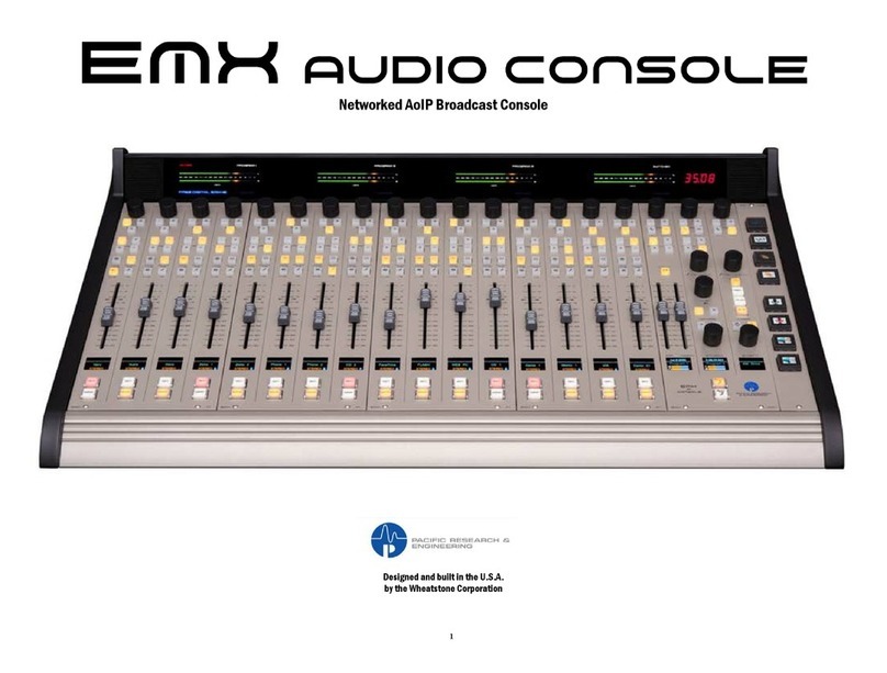
Wheatstone Corporation EMX User manual

Wheatstone Corporation
Wheatstone Corporation Talent Station TS-22 User manual

Wheatstone Corporation
Wheatstone Corporation A-5000 User manual