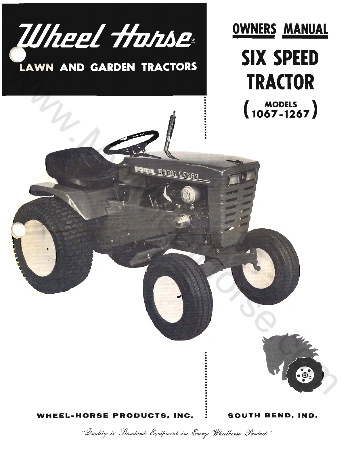
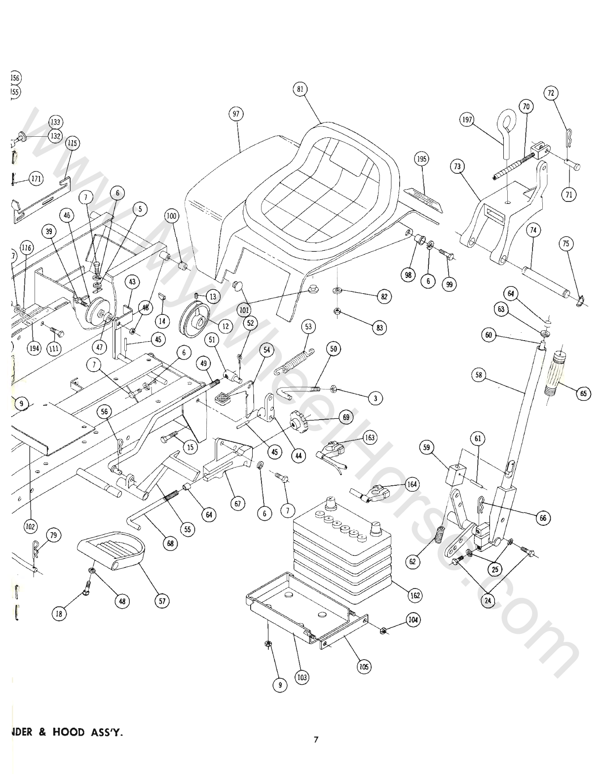
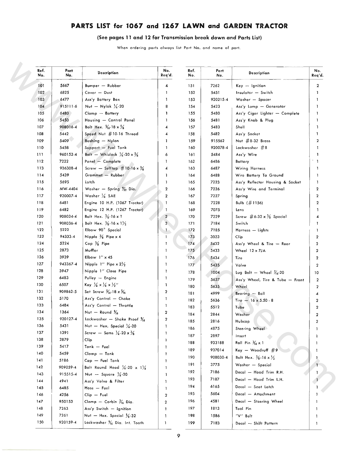
Wheel Horse 1067 User manual

WHEEL.HORSE
PRODUCTS.
INC.
OWNERS
MANUAL
SIX
SPEED
TRACTOR
(MODELS )
1067
-1267
SOUTH
BEND.
IND.
www.MyWheelHorse.com

ASSEMBLY
A.
The
Tractor
is
shipped
in
one
carton
with
the
rear
wheel
and
tire
assembly,
Part
No.
5432,
in a
sepa
rate
co
rton.
B.
Mount
rear
wheels
to
the
hubs
using
the ten
lug bolts, Part
No.1
004.
C.
Mount
front
wheels
to
spindles
using
the
%-16
x
Ya
Nylok
bolts, Part No.
908033-6
and
washers,
Part
No.
2844.
There
are
two
shim
washers,
one
.015
thick
and
one
.050
thick,
in
the
loose
part
package
for
each
wheel.
Use
one
or
both
as
shown
on
the
exploded
view
drawing
to
provide
a
close
fit.
Press
on
hub
caps.
D.
Mount
the
steering
wheel
to
steering
shaft
with
the
Woodruff
Key, Part
No
937014,
Special
washer,
Part
No.
3775,
and
the
%-16
x ~
bolt,
Part
No.
908030
-4.
Press
on
steering
wheel
insert.
BATTERY
The
battery
installed
in
the
tractor
is
a
dry
charged
battery.
It
is
important
that
you
properly
pre-
pare
this
battery
to
insure
good
service
and
long
life.
1.
Remove
vent
caps.
Remove
or
destroy
any
sealing
device
which
may
have
been
used
to
close
or
restrict
the
vent
openings.
2.
Fill
each
cell
of
the
battery
to
the
proper
level
with
the
battery
electrolyte.
NOTE:
Temperature
of
battery
and
electrolyte
at
time
of
filling
should
be
above
60
Q
F.
Never
fill
bat-
tery
in
the
vehicle.
3. BOOST CHARGE: 15 amps.
for
10 minutes
or
7
amps.
for
30
minutes.
Adjust
electrolyte
level,
if
nec-
essary,
after
charge.
4.
Install
battery
with
battery
posts
toward
the
rear
of
tractor.
Start
engine.
After
battery
has
been
in
service,
add
only
approved
water.
DO NOT ADD ACID.
TIRES
The
front
tires
are
16x5.50-8
and
should
be
inflated
to
12
pounds
of
air
pressure.
The
rear
tires
are
8.50
x 12
and
should
have
8
pounds
of
air
pressure.
The
tires
can
also
be
filled
with
ballast
if
desired.
Ordinarily
this
is
not
necessary
as
the
weight
of
the
operator
will
odd
sufficient
weight
for
adequate
trac-
tion.
BEFORE
YOU
START
There
is
NO
OIL
in
the
crankcase
of
the
engine
when
shipped
from
the
factory.
OIL
is
recommended
by
the
engine
manufacturer
and
must
be
followed
for
best
performance
and
long
life.
See
Engine
Manual.
lubricate
all
grease
fittings
with
a
regular
pressure
gun
lubricant
every
eight
to
ten
hours
of
operation.
Refer
to
Figure
III
for
the
location
of
grease
fittings.
A
light
machine
oil
should
be
used
on
all
moving
parts
to
keep
joints
from
wearing
and
squeaking.
Remove
oil filler
plug,
located
at
the
left
rear
side
of
the
transmission,
and
fill to
level
of
hole
with
a
good
grade
of
S.A.E.
90
oil (will
require
about
2
quarts).
The
transmission
should
be
checked
after
every
40
hours
of
use.
The
transmission
should
be
drained
once
a
year
by
removing
plug
on
bottom
to
drain
oil. Refill
as
above
paragraph.
This
is
a
regular
automotive
type
transmission
with
sliding
gears
and
should
have
the
some
care
as
your
cor.
2
STARTING ENGINE
1.
Before
starting
the
engine
fill
gas
tank
(located
under
the
hood)
with
a
good
grade
of
regular
gas,
and
open
valve
on
fuel
filter
located
below
the
gas
tank.
2.
Set
parking
broke
and
place
gear
shift
lever
in
neutral
position.
3.
Pull
throttle
lever
~
way
out
and
turn
to
the
right
to
lock it in
position.
Note:
The
throttle
control
has
a
locking
device.
Turn
the
throttle
control
to
the
left
to
unlock,
adjust
to
the
desired
position
and
turn
to
the
right
to lock.
4.
Pull
choke
lever
all
the
way
out
to
choke
en·
gine.
If
engine
is
warm
and
has
been
running,
chok
-
ing
may
not
be
necessary.
5.
The
tractor
has
a
key
starter
-
switch.
Turn
key
all
the
way
to
right
to
start
engine.
6.
When
engine
starts
push
choke
in to
off
posi-
tion
and
regulate
throttle
control
by
turning
to
the
left
to
unlock
and
push
in
or
out
to
desired
speed.
7.
Depress
clutch
pedal
on
left
side
of
tractor
be-
fore
selecting
desired
gear
range.
S.
When
starting
tractor
in
winter
it
is
desirable
to
depress
clutch
so
engine
does
not
have
to
turn
transmission.
LOW
AND
HIGH RANGE
SELECTOR
The
low
range
drive
provides
a
slower
speed
in
each
respective
gear,
by
a 4
to
1
reduction
in
speed
from
high
range.
When
the
range
selector
lever
is
all
the
way
to
the
left
it
is
in
low
range,
or
all
the
way
to
the
right
it
is
in
high
range.
(See
instruction
decal
on
cover
plate.)
Do
not
use
a
mid-point
position
on
the
range
selector
as
neutral.
Neutral
position
must
be
selected
only
with
the
standard
transmission
gearshift
lever.
low
range
is
used
for
working
heavy
bonked
snow,
tilling,
high
weeds,
or
hill
sides.
The
following
table
shows
the
speeds
available
in
each
of
the
three
forward
gears
and
the
reverse
gear.
MILES
PER
HOUR
GEAR HIGH LOW
Fir5t 2.2
.5
Second
3.4
.8
Th
ird
6.0 1.5
Reverse
2.8 .7
CLUTCHING
Don't
force
the
gear
shift
lever
if
the
gears
do
not
immediately
mesh.
Depress
clutch
pedal
all
the
way
down
and
let
up,
then
depress
again
and
shift.
To
avoid
sudden
starts,
release
clutch
pedal
slowly.
While
in
motion
do
not
shift
gears
without
depressing
clutch
pedal.
www.MyWheelHorse.com

The
clutch
pedal
also
operates
the
brakes
WHEN
DEPRESSED
All
THE
WAY
DOWN. For this reason,
you
should
depress the clutch
pedal
ONLY %
OF
THE
WAY
DOWN
WHEN SHIFTING
while
in
motion.
This clutch-
brake
pedal
combination
makes
clutching
automatic
as
you
apply
the
brakes
to
stop.
See
Figure
I.
FIGURE
I
PARKING
BRAKE
The
parking
brake
is
located
on
the
left
side
of
the
tractor
as
shown
in
Figure
I.
To
set
the
parking
brake
depress
the
clutch-brake
pedal
as
far
as
pos-
sible
and
push
the
parking
brake
down.
To
release
the
brake
depress
the
clutch-brake
pedal.
BRAKE
ADJUSTMENT
The
brake
band,
located
on
the
left
side
of
the
transmission
,
brakes
the
tran
s
mission
and
in
turn
stops
the
wheels.
To
adiust,
depress
clutch
brake
pedal
and
move
parking
brake
lever
forward
into
the
engaged
posi-
tion
.
Tighten
nut
on
brake
rod
until
both
rear
wheels
skid
when
tractor
is
pushed
-
parking
brake
en-
gaged.
Tighten
nut
another
~
turn.
The
broke
and
parking
brake
are
now
properly
adjusted.
See
Fig.
II.
FIGURE
II
3
LIFT
HANDLE
The lift
handle
is
used
to lift
or
lower
equipment
used
with
the
tractor.
Depress
the
release
button
to
lower
the
handle.
When
the
equipment
is
allowed
to
float,
the
for-
ward
travel
of
the
handle
can
be
limited
by
the
adiustable
stop.
Turn
the
hand
knob
till
the
s
top
reaches
the
desired
position.
ATTACHING TOOLS
Complete
information
on
the
assembly,
attachment
,
operation
and
service
of
the
many
attaching
tools
will
be
provided
with
each
attachment.
CARE
OF
TRACTOR
1.
Keep
tractor
greased
and
oiled
regularly.
Re-
fer
to Fig.
III
for
the
location
of
grease
fittings.
Check
transmission
and
engine
case
oil Ivels.
2.
Keep
engine
air
cleaner
clean.
This will
add
to
engine
life.
3.
Keep
tire s
properly
inflated.
See
previous
in-
structions.
4.
Keep
tractor
covered
and
in a
dry
place
when
not
in
use.
5.
Keep
grass
and
dirt
out
of
engine
cowling
as
these
will
stop
the
flow
of
air
and
decrease
en-
gine
life.
6.
LIGHTS.
To
replace
light
bulbs
remove
the
four
screws
holding
the
lens,
push
down
and
rotate
the
bulb
to
the
left, it will
then
come
out.
Replace
with
# 1156
bulb.
The
lights
may
go
off
when
the
hood
is
raised,
this
is
because
it
loses
ground
contact.
7. CLUTCH-BRAKE
PEDAL
ADJUSTMENT. The
clutch-brake
pedal
rod
may
be
turned
in
or
out
to
adjust
the
pedal
to
operator's
desired
position.
Re-
move
pin
from
rod
and
turn
rod
in
or
out
for
adjust-
ment.
There
are
also
two
holes
in
the
pedal
to
adjust
for
travel.
The
upper
hole
is
for
a
short
movement
of
travel,
the
lower
hole
is
for
a
long
movement.
8.
When
replacing
belts
or
mounting
drive
im-
plements
make
sure
all
pulleys
are
in line.
9.
BATTERY.
Check electrolyte level
periodically.
If
tractor
has
been
in
storage
it
may
be
necessary
to
recharge.
10.
Your
tractor
is
only
as
good
as
the
service
you
give
it.
See
your
Wheel
Horse
Dealer
for
a
thorough
check-up
after
each
season
of
use.
11.
When
replacing
belts
be
sure
to
purchase
gen-
uine
Wheel
Horse
belts,
as
these
belts
are
specifically
designed
for
each
application.
(NOTE:
Make
sure
all
pulleys
are
in line.)
12.
To
raise
seat
/
fender
unit
pull
knob
back.
See
Fig.
III.
Seat
should
be
latched
before
operating
tractor.
www.MyWheelHorse.com

SAFETY
SUGGESTIONS
Recommended
by
Outdoor
Power
Equipment
Institute
1.
Know
the
controls
and
how
to
stop
quickly
read
the
owners
manual.
2.
Do
not
allow
children
to
operate
machine;
nor
adults
to
operate
it
without
proper
instruction.
3.
Clear
work
area
of
objects
which
might
be
picked
up
and
thrown.
4.
Disengage
all
clutchs
and
shift
into
neutral
before
starting
motor.
Keep
hands,
feet,
and
clothing
away
from
po
wer
driven
parts.
S. Do
not
carry
passengers.
Keep
children
and
pets
a
safe
distance
away.
6.
Never
direct
discharge
of
any
moterial
to
war
d
bystanders,
nor
allow
anyone
near
machine
while
in
operation.
7.
Disengage
power
to
attachment
(5)
and
stop
motor
before
leaving
operator
position
.
8.
Take
precautions
when
leaving
machine
un-
attended
(
to
avoid
accidental
starting,
rolling
away,
accidental
dropping
of
any
attachment,
etc.)
9.
Disengage
power
to
any
attachment
when-
ever
it
is
not
in
use,
or
when
traveling
from
one
work
area
to
another.
10.
Stay
alert
for
holes
and
other
hidden
hazards.
Know
what
is
behind
you,
before
backing
up.
11.
Beware
of
steep
slopes;
reduce
speed
on
all
side
slopes
and
sharp
turns
,
to
prevent
tipping
or
losing
control.
12.
Don't
stop
or
start
suddenly
when
going
uphill
or
do
w
nhill.
13.
Use
core
when
pulling
loads
or
using
heavy
equipment.
14.
Watch
out
for
traffic
when
near
roadways.
15.
Handle
gasoline
with
core
-
it
is
highly
flammable.
a.
Use
approved
gasoline
container.
b.
Never
add
gasoline
to a
running
motor
fill
tonk
out
of
doors
wipe
up
spilled
gasoline.
c.
Replace
gasoline
cap
securely.
d.
Open
doors
if
motor
is
run
in
garage
-
exhaust
gases
are
dangerous.
16.
Keep
machine
in
good
operating
condition
and
keep
safety
devices
in
place
. Use
guards
as
instructed
in
owner
's
manual.
"
GROUND
BA
CK
6
•
BLAC~
LIG
HT
'O
·
....
ITCH
lI
Gh T[1<
WIRING DIAGRAM
) I
WARRANTY
We
warrant
WHEEL
HORSE
PRODUCTS
for
ONE
YEAR
from
date
of
purchase
against
defective
parts
and
workmanship.
We
will
replace
,
free
of
charge,
any
defective
port
,
f.o.h.
the
factory.
Wheel
Horse
Products,
Inc.,
reserves
the
right
to
make
changes
or
im-
provements
upon
its
products
without
im-
posing
any
obligation
upon
it
se
lf to
install
the
same
upon
its
product
s
that
have
been
previously
manufactured.
The
engine
and
battery
carry
a
separate
warranty
by
the
manufacturer.
FOR
ENGINE
OR
BATTERY
SERVICE
, CONTACT YOUR
LOCAL ENGNE
OR
BATTERY SERVICE HEAD·
QUARTERS.
!
All
warran
ty
claims
,
work,
shI
pments,
must
be
handled
thr
ough
your
authorl~ed
Wheel
Horse
d
ealer
1
[2,1_
~O,
TE;
90
Day
Worronty
faT
Commerciol
Use.
I
~~~
~,........
-
~
;ff,";-~vv
-
SPECIFICATIONS
(Specificolion>
subject
10
change
wilhoul
notice
.}
le
ngth
Overall
W
heelbas
e
..
.
..
........
. .
Widt
h
Overall
Width
at
Front
Wheels
Height
Height
to
Top
of
Hood
Approx.
Ship
ping
Weight
1067
Approx.
Shipping
Weight
1267
Crop
Clearance
....
. .
...
.
Fr
ome
Cleo
ranee
E
ng
in
e (
4.eycle,
single
cylinder,
air
cooled
)
E
ngin
e O
il
Capo
city
Fuel
Capacity
Transmission
Oil
Capacity
65
inches
45
1'2
inches
36
inches
33
!1
inches
40
inches
. . . .
..
35
inches
597
Ibs.
607
Ibs.
......
7X
inches
13
);2
inches
Electric
Start
5
pints
............
. . 6
quarts
2
quarts
Ti
res
(
front)
5.50
-8
Pneumatic
(16"
wheel
dia
.)
Ti
r
es
(
reor
) Terr
a-
Type
8.50
x 12" P
neumatic
(
23
" w
heel
dia.
)
Turning
Radius
(to
outside
of
outside
wheel
) 6 ' 9"
www.MyWheelHorse.com

Figure
III
LIFT
HANDLE
GREASE
5
www.MyWheelHorse.com

6
MAIN
FRAME,
FENDE
www.MyWheelHorse.com

§
~
@
~
P lI5
o
~~
~
79
18
48
mER
&
HOOD
ASS'Y
.
57
81
72
®
197
75
24
7
www.MyWheelHorse.com

Ref.
No
.
2
3
4
5
6
7
8
9
10
11
12
13
14
15
16
17
18
19
20
21
22
23
24
25
26
27
28
29
30
31
32
33
34
35
36
37
38
39
40
41
42
43
44
45
46
47
48
49
50
PARTS LIST
for
1067
and
1267
LAWN
and
GARDEN TRACTOR
Port
No
.
6456
6508
915663
·4
908034
·4
920009-4
920083
·4
908032·4
908017·4
915112-6
7220
960151
·4
7232
909849
-5
937010
908033·6
6465
937022
909554
915236·4
5638
1030
1481
6216
908015
.4
920082·4
5630
5631
5618
6396
6397
908035
·4
6943
1085
909848-5
6469
6472
5210
1278
932035-4
5628
5629
915002
·6
6951
4899
933158
1623
1536
915113
-6
2593
3935
(
See
pages
11
and
12
for
Transmission
break
down
and
Parts
Lis
t)
When
ordering
po
rts
always
list Por'
No
.
and
nome
of
Fort
.
D
escription
Au
'y
Frame
Ass'y
Headstand
Nul
%-
16
Elastic
Stop
Bolt H
ex.
%-
16
xl
Washer
Ys
SAE
lockwosher
% Plain
80lt
Hex.
%-
16
x %
Bolt K6,18 x %
Nul
U6
,18
Nylok
Ass'y
Cover
Plote
Bolt ~
.
20
x X
Whiz
lock
Pulley -
Transmission
Set
Screw
X
·20
X
)(6
Nlyok
Key -
Woodruff
~1
x
Ya
Bolt %
.16
x
Ys
NyJok
Hub
-
Wheel
Key # 15
Woodruff
Set
Ccrew
Squore
Head
%.
16 x 1
N
ut
Hex.
%-
16
Jam
Axle -Front
Filling -
Grease
Fitting _
Grease
45
0
Au
'y Pin &
Plate
B
olt
Hex
)(
6-18 x
Y2
l
ockwasher
~,
Plain
Au
'y
Spindle
R.H.
Ass'y
Spindle
LH.
" E" Ring % Oia.
Support
-
Steering
Bushing
Bolt H
ex.
%
.16
x
1
~
Ass'y Sh
aft
-
Upp
er
Steering
Collar
Set
Screw
X
-20
x ~ Nylok
Ass'y
Steering
Sh
aft
- l
ower
Ass'y B
ear
ing
&
Housing
Washer
- Shim
(.
015
)
Washer
-Shim (.
050
)
Coller
Pin
J{,
x 1X
Au
'y Ball
Jo
int
R.H.
Ass'y Ba
ll
Joint
LH.
Nut
%-
24
NyJok
Ass'y
Idler
Arm
&
Shaft
Arm -Clutch Rod Pivot
Roll Pin
X
x1
~
Pulley -Idler
Bushing
Nut
-
Nylok
%.16
Rod -Clutch
R
od
-Broke
No
.
Req'd .
9
2
6
10
6
2
10
4
4
2
2
4
2
1
3
8
8
1
3
2
3
3
2
2
3
8
Ref.
No
.
51
52
53
54
55
56
57
58
59
60
61
62
63
64
65
66
67
68
69
70
71
72
73
74
75
76
77
78
79
80
81
82
83
84
85
86
87
88
89
90
91
92
93
94
95
96
97
98
99
100
Part
No
.
1861
932017·4
1014
5544
2267
933504·4
4421
5448
4438
5449
933168
3624
3578
3680
1000
933506·4
5640
2179
5280
3931
9321204
933503·4
3926
3988
936125
7230
5455
5457
933503·4
6490
Description
Stud
-Clutch Rod
Cotter
Pin
Spring
-Clutch
Ass'y l
ever
& Knob -Broke
Pedol
-Clutch
Hoir Pin
Footrest
Ass
'y
lift
lever
Plunger
Rod
Roll Pin
Spring
Guide
-
Plunger
Rod
Cap
- Plu
nger
Rod
Grip
-
Handl
e
Ha ir Pin
Quadrant
Rod - H
eigh
t
Control
Knob -
Height
Cont
ro
l
Ass'y
CabJe
-
lift
Pin -Clevis
~
Oia.
H
air
Pin
Cotter
Hitch
Pin -Hitch
Snap
Ring %
Shaft
Ass'y
Hood
Brocket
-
Hood
Hinge
Bushing -
Nylon
H
air
Pi
n
Cotter
Rod -
Hood
Pi
vot
7070
Seat
-
Complete
92oo0B·4
Washer
)(6
SAE
915662-4
Nut
)(6
-18
El
astic
Stop
5467
5469
933182
5505
5468
915932-4
5466
5522
5438
5437
6509
908045·4
920084·4
5660
5666
908182·4-
4937
L
ever
-
Hood
l
atch
Knob
IRoll Pin K6x
78
Roller -
Rubb
er
Roller -
Steel
Nut
-High
Crown
# 10-24-
Speed
Nut
Push
On
~ Dio.
Rod - H
ood
latch
Ornament
-
Hood
Speed
Nut
-Push
On
Ys
Oia.
An
'y Belt
Guard
Screw
H
ex.
K6-
14 x
Y.
l
ockwasher
-
Plain
K,
Ass'y fe
nd
er
Bushing -
Nylon
IBolt
%.24
x
Ys
H
ex.
Spacer
I
No.
Req'd.
2
2
2
2
2
2
2
2
•
•
2
2
2
2
2
2
2
2
www.MyWheelHorse.com

Ref.
No.
101
102
103
104
105
106
107
108
109
110
111
112
113
114
115
116
117
118
119
120
121
122
123
124
125
126
127
128
129
130
131
132
133
134
135
136
137
138
139
140
141
142
143
144
145
146
147
148
149
150
PARTS LIST
for
1067
and
1267
LAWN
and
GARDEN TRACTOR
(See
pages
11
and
12
for
Transmission
break
down
and
Parts
List)
When
ordering
parfs
always
list
Port
No
.
and
n
ome
of
port
.
Pari
No
.
5667
6825
6477
915111-6
6480
5450
908016
-4
5442
5409
5458
960152
-4
7222
926308·4
5439
5695
Description
Bump
e r -
Rubber
Cov
er
-
Dust
Ass'y
Battery
Box
Nut
-Nylok };I'-20
Clamp
-
BaH
ery
Hou
sing
-
Control
P
ane
l
Bo
lt H
e;K,
~6
·18x
Ya
Speed
Nut
#10·16 Thr
ead
Bu
shing
-
Nylon
Support
-Fuel Tonk
Bo[t -
Whizlock
/;1.20 x
Va
Panel -
Complete
Screw
-
Selftep
# 10·16 x %
Grommet
-
Rubber
L
atch
MW-4404
Washe
r -
Spring
1-3'2
Dia.
920007
-4
Washer
X
SAE
6481
Engine
10 H.P.
(1067
T
rac
tor
)
6482
Engine 12 H.P. (1267 Troctor)
908034
·4 Bolt Hex. %
-16
xl
908036
·4 Bolt Hex.
%.
16 x 1
!1
5222
Elbow
90
° Special
94333·4
Nipple % Pipe x 4
5224
Cap
% Pipe
2873 Muffler
3939
Elbow I " x 45
943367
·4 Nipple
I"
Pipe x 2
!1
3947
Nipple
I " Close Pipe
6483
Pulley -Engine
6507
Key X x X x
!1"
909862·5
Set Screw
~4·
18
X
){6
5170
An
'y Control -
Choke
6484
An
'y Control -Throttle
1364
Nut
-Round
Ji'6
920127
.4 Lockw
as
her
-
Shake
Proof
~6
5431
Nut
-Hex. Special
),.{
.20
1391
Screw
-Sems
!{.20x%
2879
Clip
5417
T
ank
-Fuel
5459
Clamp
-Tonk
5186
Cap
-Fuel Tank
909059
·4 Bolt Round
Head
),.{
·20 x 1
~
915515
·4
4941
6485
4256
950153
7263
7261
920159
·4
Nut
-SCjuare ),.{.20
An
'y
Valve & Filter
Ho
se -Fuel
Clip -Fuel
Clamp
-Corbin
P<6
Oi
a .
An
'y Switch -Ignition
Nut
-Hex. Special
%·32
L
ockwosher
U6
Dia . Int. T
oo
th
No.
Req'd.
4
1
1
8
1
I
4
4
1
1
6
1
4
I
1
2
2
1
1
2
2
1
1
1
1
1
1
1
1
1
2
1
1
2
2
1
I
I
1
1
1
1
1
1
I
2
2
1
1
1
Ref.
No
.
151
152
153
154
155
156
157
158
159
160
161
162
163
1
64
165
166
167
168
169
170
171
172
173
174
175
176
177
178
1
79
180
181
182
183
184
185
186
187
188
189
190
191
192
193
194
195
196
197
198
199
Part
No
.
7262
5451
920215
·4
5423
5480
5481
5483
54
82
915562
920078·4
5484
6486
6487
6488
7223
7226
7227
Description
Key -
Ig
nition
Insu
lator
-Switch
Washer
-
Spacer
A
n'y
Lomp -
Generotor
Ass'y
Cigar
lighter
-
Complete
Ass'y Knob & Plug
She
ll
Ass'y
Socket
Nut
# 8-
32
B
rass
lockw
ashe
r # 8
Au
'y Wire
Battery
Wiring
Harness
Wire
Ba
ttery
To
Ground
Ass'y
Re
fle
ctor
H
ousing
& So
ck
et
Ass'y Wire
and
Terminal
Spring
7228
Bulb
(#
1156)
7075
l
ens
7229
Screw #6-32 x
Ya
Special
7184
Switch
7185
Ho rn
en
-Lights
3023
Clip
5432
Au
'y Wheel &
Ti
re - R
ear
5433
Wheel
12x7JA
5434
Tire
5435
Valve
1004
lu
g
Bo
lt -Wheel
P<6-20
5637
Ass'y Wheel, Tire &
Tu
be
-
Fr
ont
5635
Wh
ee
l
4999
Be
aring
-Ball
5
636
Ti
re -16 x
5.50
- 8
5512
Tube
2844
Washer
2816
Hu
bcap
4
875
St
eer
ing Wheel
2897
In
sert
933188
Roll
Pi
n
3{6
x 1
937014
Key
-
Woodruff
# 9
908030
·4 Bolt H
ex.
%.1
6 x X
3775
Wa
s
her
-Special
7186
7187
6165
5604
4581
1813
1586
7183
D
eca
l - Hood Trim
R.H.
Dec
a l - Hood Trim l.H.
Decal -
Sea
t
la
tch
Decal -
Attachment
Decal -
Steering
Wheel
Tool
Pin
"V" Belt
Decal -Shift
Patt
ern
No.
Req'd.
2
1
1
1
1
1
1
1
2
1
1
I
I
1
I
2
2
2
1
4
1
1
2
2
2
2
2
10
2
2
4
2
2
2
2
I
I
1
1
1
1
I
1
I
I
I
I
I
I
____
~
____
___
L .
_____
____________
~
__
9
www.MyWheelHorse.com

,
.'
1
89
18
19
16
o
178
STEERING
&
WHEEl
ASS'Y
.
www.MyWheelHorse.com

77
79
78
Transmission
34
37
www.MyWheelHorse.com

,
50
60
TR
ANSMISSION PARTS
LIS
T
"'
(
Ord
er No.
506
0 for
Com
p
l
e~e
T
ra
nsmission)
When
ordering
paris
atways
list
Port
No.
end
N
ome
of
Pert.
Ref.
No.
Part
No.
1
7066
No.
Descri
pti
on Req 'd. Item Pa rt
__
No·
C
. + _
--"N
",
o
,-
. _ ---i_-=.:Descrip"""';o"n'---_
41
72
35
Spri
ng - Cyli
nd
ri
cal
N
o.
_ _
-+-,
Req'
d.
2 15
33
3
1532
4 1
542
5
1526
6 15
29
7 1
46
1
8 12 13
9 391 5
10
694
1
11
15
30
12 1531
13 1
232
14
719
4
15
7195
16
719
6
17 71
97
18
7198
19
7199
20
908138
·4
21
91
5663
-4
22
'
920009
·4
23
7202
24
7203
25
71
69
26
72
01
27
72
04
28
15
18
29
51
75
30
7205
31
720
6
32
7207
33
720
8
34
7209
35 3
517
36
3
51
8
37
72
13
38
721 4
39
7200
4Q
933209
--=
--'-
~
Cas
e -
R.
H. 1
B
ea
ri
ng
8011
1
}2
I.
D. 2
B
eering
- N
ee
dle 1"
1.
0 . 1
B
earing
- N
eed
le
Va"
1.
0. 1
B
earing
- Ne
edl
e IX" 1.0. 2
B
ea
ring - N
ee
dle % 1.0. 2
Sec
I - O
il
Va
Sh
af
t 1
Sec
I Oil 1
Va
Sha
ft
2
Pin -
Dowel
2
Ce
se
-
L.
H.
8
eari
ng
-
Need
le 1"
1.
0 .
B
ea
ring -
Ne
edle %
1.
0.
See
l - O
il
1" Sh
aft
- Bro ke
E
nd
Cop
R.H.
E
nd
Cop
l.H.
Geer
-
Differential
Ri
ng 1
G
ear
- A
xle
2
Gea
r - Di
ff
eren
tial Pini
on
10
Washe
r - T
hr
u
st
2
Bol
t % . 16 x 3
Y.;"
5
N
ut
- Elas
ti
c
Stop
78
·16 5
W
as
h
er
- F
lat
Ys
SAE 10
A
xle
-Rear
R.H
.
A
xle
- Re
ar
l.H
.
Snap
Rin
g - H
eavy
D
uty
- E
xte
rnal
2
Shoff
-
Inpu
t
Geer
&
Spline
1
Beo
ri
ng
-
Needle
Va
1.
0 . 4
Pinion
Gear
&
Spline
Gear
-
Sl
idi
ng
1
G
ear
-
Reduction
1
B
ea
r
ing
-
Needle
Va
1.0. 2
Sh
aft
- Re
duc
tion
Gea
r 1
Ass/y.
Shift
Fo
rk ' 1
Ba
ll
- S
top
3
Sp
ri
ng
-
St
op 2
B
olt
- De
ten
t 1
l
ever
-
Shift
1
B
ody
2
Roll Pin 2
42
5 173 G
ear
- Hi
an
d
2nd
43
51 74 G
ea
r -
low
an
d Rever
se
44
5615
Roil - F
ron
t
Sh
ift
45
56 16 Roil - R
ear
Shift
46
35
03
Fork -
Shift
47
93315
6 Roll Pin
Ys
x 1
48
56
14
Pi
n -
Shift
S
top
49
3525
Gear
-
Cl
uste
r
50
15
04
B
earin
g - Br
onze
%
1.
0.
51
35
28
Gear
-
Reduct
i
on
Pi
nion
52
3527
Geo
r -
Reduct
ion
53
3910
Sh
aft
-
Cl
uste
r
Ge
a
54
93701
4 Key :;; 9
Woodruff
55
42
04
Gear
- R
ever
se Id le
56 15
16
B
ushing
- B
ronze
}2"
1.
0 .
57
3
90
9
Shaft
58
41
66
G
ear
- B
roke
Sh
aft
59 39
02
Drum - Broke
60
937
022
Key # 15
Woo
druff
61
93613
1
Snopring
1" S
ha
ft
62
4437
As
s/
y. Broke Bond &
Li
ning
63
90
8002·
4 Bolt - H
ex
~
.2
0
x %
64
920
081-4
l
ockwasher
X" Oio.
65
94
34
60
Plug X
Pipe
66
94
3420
Pl
ug
%
Pipe
67
3912
G
as
ket
68
908043
·4
Bo
lt Hex %
·16
- 3}2
69
908038
·4
Bo
lt Hex
%·1
6 x 2
70
9
15113·6
Nut
Vs
·16
Nylok
71
9
43322
N
ipple
% Pipe x 1
72
943003
Coupling
Va
Pipe
~
3
56
32
Au
/y.
Shift
Stick
74
12
39
Set
Screw
X·
20 x % Dog P
oin
t
75
915
111·4
N
ut
H
ex
j{
.20
'" 76
3577
B
oot
77 1
00
1
Knob
78
7217
An
'
y.
H
an
dle -
Shift
79
933184
Roll
Pin
3<6
x %
_ '
,,
0
'--
'------'
741
""'--_'---
W=
osher
-
Thl
ust
'
Not
Included
in
No.
5060
Assembly.
ATTACHMENTS AVAILA
BL
E
MODEL
1067-126
7 TRACTOR
48"
ROT
A RY M OW
ER
(
RL
-4
86
)
TR
AILIN
G CU
LTI
VAT
OR
(
AC-7)
42"
ROT
A RY MOWER (RL-426) TWO
SE
CT
ION
CU
LT
IVA
TO R (
AC-675
)
36
/1
ROTARY MOWER (
RL
-
36
7)
GR
AD
ER
BL
A
DE
(M B-405)
3
7"
SNO
W THROWER (
ST
-
376
)
SP
IKE TOOTH HA RROW (
PH-1
83)
5
0"
SI
CKLE BA R
MO
WER (SMS-5C6) 4-W
HEEL
UTILITY
WA
G
ON
(U
W-
645
)
42" DOZER
BL
A
DE
(
BD
-
426
) 2
-W
HEEL
D
UM
P TRAI
LE
R (LTD-2 44)
32"
DISK (
DP
-861)
SP
IK
ED
D
ISK
AER
AT
OR
(SC-1
52)
36"
TIL
LER (
RT-
367
) L
AWN
ROLL
ER
(LR-322)
12" PLOW (
PP
-513) G
ANG
MOWER 60" CUTTI
NG
WI
D
TH
-
REEL
T
YP
E (
SG
M-603
)
OPTI
ONA
L ACCESSORIES
MODE
L 1
067
-
1267
TRACTOR
FRONT
AND
RE
A R W
HEE
L DIS
CS
(WD
-7)
POW
ER
T
AK
E-O
FF
(PTO-
66
)
REAR
WH
EE
L WEIGHTS (
WW
-1
26
)
FR
ON
T WHE
EL
WEIGHTS (W F-60)
ATTACHMENT C
LUT
CH (PT-6)
T
IR
E
CHAINS
(TC-13)
DUAL
WH
EE
LS
(
DW-62
)
AUXILIARY
HITCH (AH-63)
1
2
2
1
1
2
1
1
2
1
2
2
1
1
5
6
1
2
Printed
in
U.S.A. 1·1 ·
67
FORM
NO.
346·347
www.MyWheelHorse.com
This manual suits for next models
1
Other Wheel Horse Tractor manuals

Wheel Horse
Wheel Horse 208-4 User manual

Wheel Horse
Wheel Horse 867 User manual

Wheel Horse
Wheel Horse 605 Troubleshooting guide

Wheel Horse
Wheel Horse B-81 Reference manual

Wheel Horse
Wheel Horse B-81 User manual

Wheel Horse
Wheel Horse D-250 Operating instructions

Wheel Horse
Wheel Horse 1-7441 User manual

Wheel Horse
Wheel Horse 1-6051 User manual

Wheel Horse
Wheel Horse A Series User manual

Wheel Horse
Wheel Horse 1-3745 User manual