Whipple M-6066-F150SCA User manual

Installation Manual: Whipple SC 21_F150_R15
Last Updated: April 9
th , 2022
Page 1 of 49
www.whipplesuperchargers.com
WHIPPLE-FORD PERFORMANCE SUPERCHARGER
INSTALLATION MANUAL
2021 AND UP FORD 5.0L F150
PART NUMBERS: M-6066-F150SCA, M-6066-F150SCB
WHIPPLE SUPERCHARGERS
3292 NORTH WEBER AVE
FRESNO, CA 93722
TEL 559.442.1261
FAX 559.442.4153
WWW.WHIPPLESUPERCHARGERS.COM
PREMIUM FUEL ONLY (91 OCTANE OR BETTER ALWAYS) RON+MON/2
CALIFORNIA AIR RESCOURCE BOARD EXECUTIVE ORDER #D231-71
COMPETITION BASED PRODUCT MAY BE USED SOLELY ON VEHICLES USED IN SANCTIONED COMPETITION
WHICH MAY NEVER BE USED UPON A PUBLIC ROAD OR HIGHWAY

Installation Manual: Whipple SC 21_F150_R15
Last Updated: April 9
th , 2022
Page 2 of 49
www.whipplesuperchargers.com
INTRODUCTION
Before beginning installation, please read this manual and important notes:
•Please read the installation manual and verify that all items are present. If you are missing hardware or have any
questions, please contact your dealer or Whipple Superchargers before you start the installation.
•Premium fuel (US 91 octane) is required to prevent spark-knock/detonation under certain operating conditions. Other
countries must meet US 91 octane standards, RON+MON/2. If fuel of less than 91-octane is present in the
vehicle fuel tank, the tank must be completely drained and refilled with 91 or higher octane to 1/8th of a
tank. The fuel system is returnless, therefore, initial fuel in the system will be low octane. Drain all fuel!
•Operating your engine without the Whipple Calibration can result in engine damage or failure and will void your
warranty.
•Supply your VIN number (along with gear ratio, transmission type, throttle body type and any changes to vehicle) to
Whipple ahead of SC installation so your PCM calibration can be built prior to the SC installation to minimize any down
time. NOTE: Whipple does not support long tube headers or cat removal. While the vehicle may run correctly, it will
no longer be emissions legal and therefore not supported.
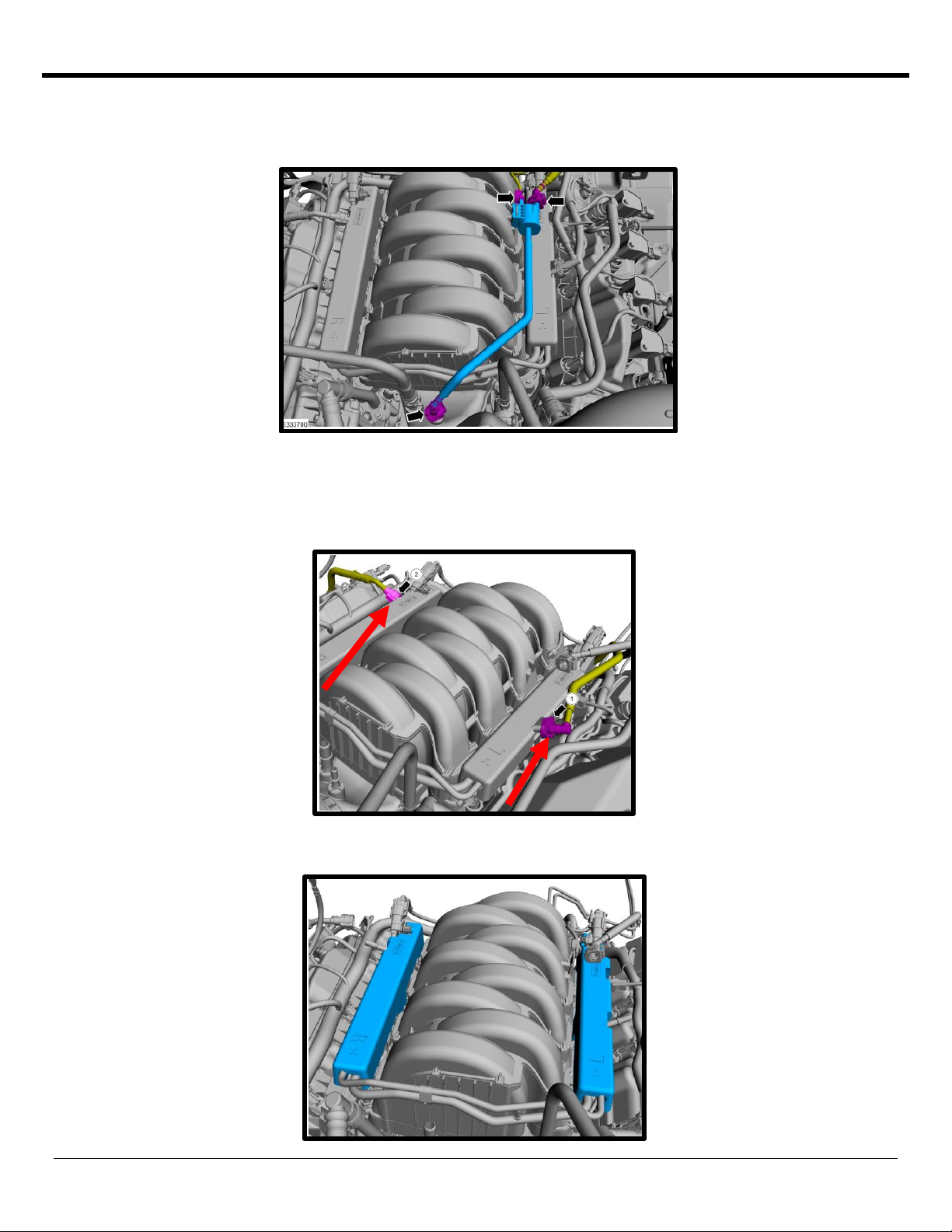
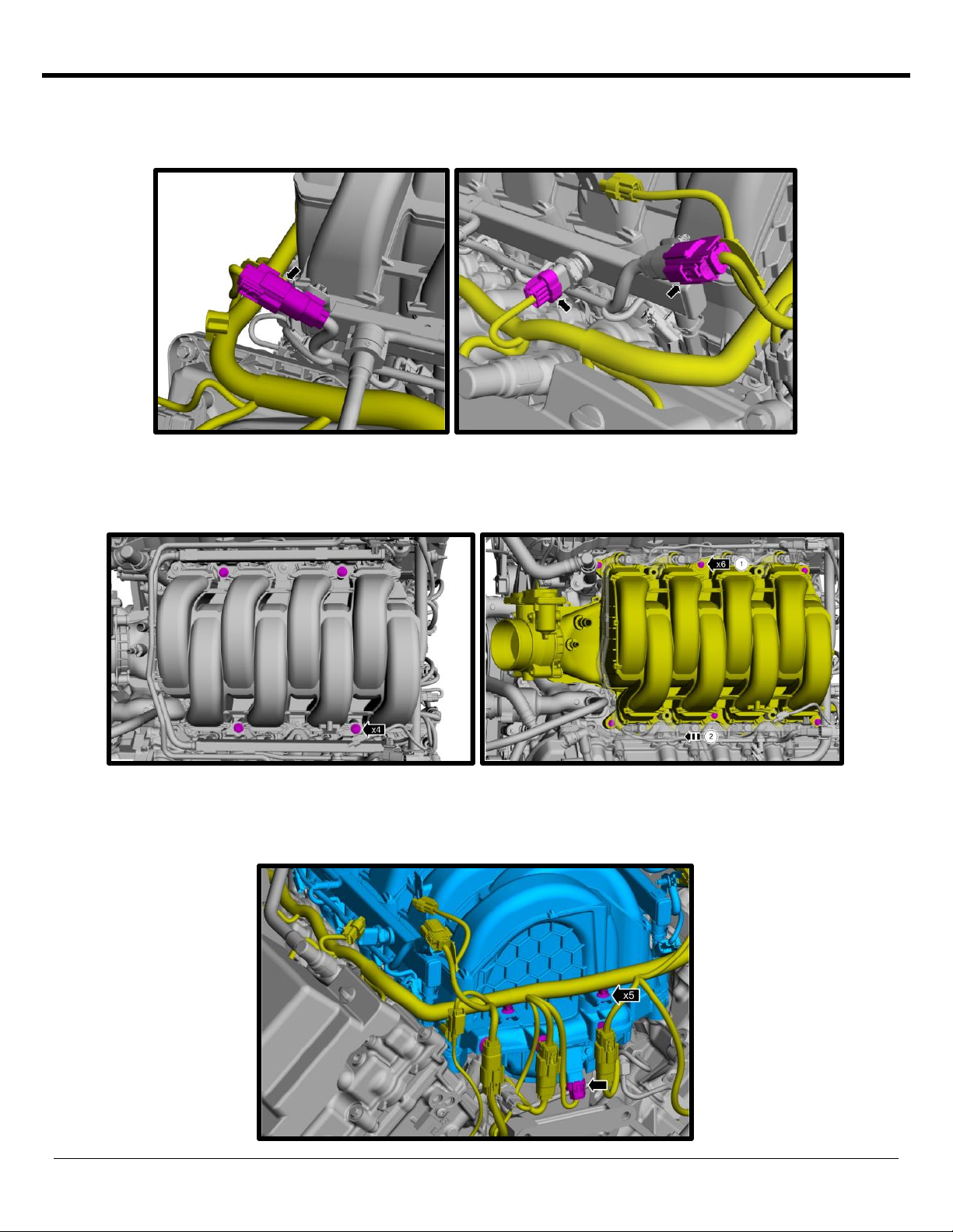
•Instructions reference LH (Left Hand) and RH (Right Hand) side of vehicle. This is if you’re sitting in driver’s seat facing
forward.
•
NEVER MANUALLY MOVE THE BYPASS ACTUATOR, YOU CAN RUPTURE THE INTERNAL DIAGHRAM.
•COMPETITION BASED PRODUCT MAY BE USED SOLELY ON VEHICLES USED IN SANCTIONED
COMPETITION WHICH MAY NEVER BE USED UPON A PUBLIC ROAD OR HIGHWAY, UNLESS PERMITTED
BY SPECIFIC REGULATORY EXEMPTION (VISIT THE “EMISSIONS” PAGE AT
HTTP://WWW.SEMASAN.COM/EMISSIONS FOR STATE-BY-STATE DETAILS.
•COMPETITION BASED PRODUCT IS LEGAL IN CALIFORNIA ONLY FOR RACING VEHICLES WHICH MAY
NEVER BE USED, OR REGISTERED OR LICENSED FOR USE, UPON A HIGHWAY.
•IT IS THE RESPONSIBILITY OF THE INSTALLER AND/OR USER OF THIS PRODUCT TO ENSURE THAT IT
IS USED IN COMPLIANCE WITH ALL APPLICABLE LAWS AND REGULATIONS.
RECOMMENDED TOOLS AND SUPPLIES
The following items are not included in this supercharger kit and it is strongly recommended that they're used for ease of
installation or maximum performance:
Engine Oil
Whipple highly recommends running Ford Motorcraft 5W-50 full synthetic motor oil (PN #XL-5W50-QGT) vs the stock
5W-20. You will need up to 8 quarts for an oil change along with a Motorcraft oil filter #FL-500.
Tools
¼” and 3/8” torque wrenches. Safety glasses, metric wrench set, electric or air drill, ¼”, 3/8”, ½” assorted metric socket
set, 5mm ball head allen, 3/8” assorted metric allen socket set, 3/8” assorted torx socket set, 8mm hex allen wrench, ½”
breaker bar, flat head and Philips screw drivers and drain pan (for coolant). Heat gun or small torch for heat shrinking.
Electric tape. Trim pad tool (for pushpin removal). Clean shop towels.
Tie Straps
These will be useful for securing the wiring harness away from the installation area as directed in the instruction manual.
They are inexpensive and will be very handy during installation. You will need an assortment of 4”, 8” and 12”.
Sealants, Chemicals and Lubricants
Anti-seize for bolt and spark plug threads (use only when stated, otherwise the torque value must be reduced). Assembly
lubricant (white lithium grease or Lubriplate). Cleaner/degreaser such as carb cleaner. Blue Loctite #243 or equivalent.
You’ll be required to fill your intercooler system with approximately 2 gallons of distilled water and Ford Factory equivalent
engine coolant, (50/50 mix only). This is not supplied in the system, you can find the coolant at any local auto parts store.
NEVER USE TAP WATER, as it can corrode and create poor performance.

Installation Manual: Whipple SC 21_F150_R15
Last Updated: April 9
th , 2022
Page 3 of 49
www.whipplesuperchargers.com
PRE-INSTALLATION CHECKLIST
Before installing your Whipple Supercharger Kit, complete the following checklist.
1. Verify Condition of Vehicle: Before the supercharger kit is installed, ensure the engine runs smoothly and that the
factory malfunction indicator light (MIL) is off. Only install the supercharger kit if the engine runs smoothly
and
the
MIL is off.
2. !! CAUTION !! This product is intended for use only on STOCK, UNMODIFIED, WELL-MAINTAINED
engines. Installation on a worn-out or modified engine is not recommended and not supported. High
mileage-based vehicles (100k+) should be well maintained, up to date on service and change fuel
pump assembly to ensure proper fuel flow. Spark plugs with 10,000 miles or more should be changed
prior to installing SC (see pre-defined gap instructions).
3. Verify Fuel System: Supercharger systems demand more fuel flow, fuel PSI should be checked post installation to
validate proper flow.
4. Assess Cleanliness of Installation Area: Make sure your work area and the under-hood area are free from debris.
This supercharger is a high-quality, close-tolerance compressor and must not be subjected to contamination by dirt
or any type of foreign material. If necessary, vacuum around engine to remove any foreign material.
5. !! CAUTION !! DO NOT remove the protective seal on the supercharger prior to installation. Foreign
material entering the supercharger will automatically void all warranties.
6. Identify Supercharger Kit Components: Before beginning installation, identify all the components of your Whipple
Supercharger Kit and ensure all items are present and undamaged.
7. !! CAUTION !! Do not attempt to start the engine before adding the supplied Supercharger Oil to
the supercharger!
SAFETY PRECAUTIONS
CAREFULLY READ THE IMPORTANT SAFETY PRECAUTIONS AND WARNINGS BEFORE PROCEEDING WITH
THE INSTALLATION!
Appropriate disassembly, assembly methods and procedures are essential to ensure the personal safety of the individual
performing the kit installation. Improper installation due to the failure to correctly follow these instructions could cause
personally injury or death. Read each step of the installation manual carefully before starting the installation.
•Always wear safety glasses for eye protection.
•Place the ignition switch in the off position.
•Always apply the parking brake when working on vehicle.
•Block the front and rear tire surfaces to prevent unexpected vehicle movement.
•Operate the engine only in well-ventilated areas to avoid exposure to carbon monoxide.
•Do not smoke or use flammable items near or around fuel system.
•Use chemicals and cleaners only in well-ventilated areas.
•Batteries can produce explosive hydrogen gas which can cause personal injury. Do not allow flames, sparks or
flammable sources to come near the battery.
•Keep hands and any other objects away from the radiator fan blades.
•Keep yourself and your clothing away from moving parts when the engine is running.
•Do not wear loose clothing or jewelry that can be caught in rotating or moving parts.

Installation Manual: Whipple SC 21_F150_R15
Last Updated: April 9
th , 2022
Page 4 of 49
www.whipplesuperchargers.com
GLOSSARY OF TERMS
ABBREVIATION
DESCRIPTION
DTC
Diagnostic Trouble Code
ECT
Engine Coolant Temperature
EGR
Exhaust Gas Recirculation
ETC
Electronic Throttle Control
EVAP
Evaporative emissions system
FHSCS
Flat Head Socket Cap Screw
IAT
Inlet Air Temperature
IC
Intercooler
ID
Internal Diameter
LB-IN
Pound-force inch
LB-FT
Pound-force foot
LH
Left Hand Side (from driver
seat)
LTR
Low temp radiator
MAF
Mass Air Flow
MAP
Manifold Absolute Pressure
MY
Model Year
OBD
On Board Diagnostics
OD
Outside Diameter
PCV
Positive Crankcase Ventilation
PSI
Pound per Square Inch
RH
Right Hand Side (from driver
seat)
SC
Supercharger
SHCS
Socket Head Cap Screw
TPS
Throttle Pressure Sensor
TRQ
Torque
WARNING
**NOTICE: Installation of Whipple Supercharger products signifies that you have read this document and have
agreed to the terms stated within.
It’s the purchaser’s responsibility to follow all installation instruction guidelines and safety procedures supplied with
the product as it’s received by the purchaser to determine the compatibility of the product with the vehicle or the
device the purchaser intends to install the product on.
Whipple Superchargers assumes no responsibility for damages occurring from accident, misuse, abuse, improper
installation, improper operation, lack of reasonable care or all previously stated reasons resulting from
incompatibility with other manufacturer’s products.
There are no warranties expressed or implied for engine failure or damage to the vehicle in any way, loss of use or
inconvenience or labor reimbursement. This includes merchantability and fitness.
The information contained in this publication was accurate and in effect at the time the publication was approved
for printing and is subject to change without notice or liability. Whipple Superchargers reserves the right to revise
the information presented herein or to discontinue the production of parts described at any time.

Installation Manual: Whipple SC 21_F150_R15
Last Updated: April 9
th , 2022
Page 5 of 49
www.whipplesuperchargers.com
SUPERCHARGER INSTALLATION INSTRUCTIONS
It is strongly recommended that you read through this guide before you begin installing the Whipple Supercharger.
1. Follow the supplied flash tool instruction manual for the Whipple Superchargers calibration process.
2. Using an air hose, blow off any loose dirt or debris from engine compartment. If really dirty, then steam clean the
engine compartment before proceeding to the next step.
3. Release the fuel system pressure.
WARNING Fuel in the system remains under high pressure even when the engine is not running. Before working
on or disconnecting any of the fuel lines or fuel system components, the fuel system pressure must be relieved. Failure
to do so can result in personal injury.
WARNING Do not smoke or carry lighted tobacco or open flame of any type when working on or near any fuel-
related components. Highly flammable mixtures are always present and can be ignited, resulting in personal injury.
A: Disconnect the Fuel Pump Control Module electrical connector. This is located under the bed, near the spare tire.
B: Start the engine and allow it to idle until it stalls.
C: After the engine stalls, crank the engine for approximately 10 seconds to make sure the fuel injector supply manifold
pressure had been released.
D: Turn the ignition switch to the OFF position.
E. Reconnect the fuel pump driver module.
4. Locate the battery on the passenger side of vehicle. With an 10mm wrench disconnect the (-) negative battery
cable. Make sure the cable is far enough away from the battery that it does not accidentally touch the battery and
make connection during the installation.
5. With a cool engine drain the coolant into a clean drain pan for reuse later. Remove the radiator cap to vent the
system. (Be careful not to remove the radiator cap if the engine is still hot). The drain petcock is located on the
bottom, driver side of radiator. Loosen spigot and let it drain into pan. Add a 3/8” ID hose to the end of the petcock
for cleaner procedure.

Installation Manual: Whipple SC 21_F150_R15
Last Updated: April 9
th , 2022
Page 6 of 49
www.whipplesuperchargers.com
6. Lift the front of the vehicle using the Ford recommended lifting points and place on to safety stands.
7. Remove the factory plastic radiator shroud by pulling the center of the (9) push pins and then out. Use a flat head
screw driver to pry the center head up. This will all be reused.
8. Disconnect the factory camera and windshield washer fluid connection from front grill area when applicable.
9. Remove the (2 per side) push pins from the lower grill shell in the inner fender area. Pull the lower grill shell section
from the vehicle.

Installation Manual: Whipple SC 21_F150_R15
Last Updated: April 9
th , 2022
Page 7 of 49
www.whipplesuperchargers.com
10. Remove the (4) bolts using a 10mm socket and the (2) push pins from the upper side of the grill shell. Remove the
(2) lower bolts from the bottom side of the grill shell.
11. Remove the (4) pin-type retainer. Pull up and disengage the locating pins along the top of the grill. Pull forward on
center of the grill to remove.
12. Remove the factory make-up air plastic quick connect fitting from inlet tube. This tube will be used later.

Installation Manual: Whipple SC 21_F150_R15
Last Updated: April 9
th , 2022
Page 8 of 49
www.whipplesuperchargers.com
13. Disconnect the (2) quick connect fittings from air inlet tube. Using a 9/32” nut driver, loosen the factory hose clamp
securing the air inlet tube to the throttle body and airbox. Carefully cut the electric tape securing the ETC wires to
the throttle body. Disconnect the electronic throttle electrical connector by pushing up on the safety lock and then
squeezing the connector and pulling away.
14. Using a 13mm socket, remove the (1) factory fastener securing airbox to the fender. Using a panel pulley or flat
head screw driver, remove the (2) push-pins from the factory air snorkel. Remove airbox from vehicle.
15. Remove the driver side valve cover PCV line quick connect fittings from the intake manifold by squeezing the
connector and pulling away. Remove from valve cover by squeezing the connector and pulling away. This tube will
be reused.

Installation Manual: Whipple SC 21_F150_R15
Last Updated: April 9
th , 2022
Page 9 of 49
www.whipplesuperchargers.com
16. Disconnect the EECVP (EVAP) solenoid electrical connector by squeezing locking tab and pulling away. Disconnect
the EVAP solenoid quick connect fitting hose from the EECVP solenoid and from the intake manifold by releasing
locking tab and pulling away.
17. Carefully remove the factory fuel line by releasing the safety lock, then squeezing the connector and pulling back.
The fuel system may still have pressure, use protective eyewear and multiple rags to catch any possible fuel leak.
NOTE: THIS FUEL LINE HAS A CHECK VALVE, DO NOT FLIP ORIENTATION. DO NOT REMOVE FROM DI
PUMP TO ELIMINATE CONFUSION. 90-DEG END ALWAYS CONNECTS TO FUEL FEED SUPPLY!
18. Remove fuel rail foam insulation, these will not be reused.

Installation Manual: Whipple SC 21_F150_R15
Last Updated: April 9
th , 2022
Page 10 of 49
www.whipplesuperchargers.com
19. Disconnect the (2) injector harness 6-way pigtails and push connectors out of the way. Remove the fuel PSI sensor
electrical connector from the driver side fuel rail by releasing the locking tab and squeezing connector, then pulling
away.
20. Loosen the (4) bolts holding the fuel rails down, these go through to the cylinder head using a 10mm socket and 6”
extension. Fuel rail does not need to be removed yet. Loosen the (8) manifold to cylinder head bolts using an 8mm
socket.
21. Use compressed air and remove any direct or foreign material from cylinder head, block and surrounding area of the
fuel rail and injectors. Remove the intake manifold from the engine. To do so, remove the (5) wire harness push pin
supports from the back of the intake manifold and disconnect the 4-way MAP sensor connector.

Installation Manual: Whipple SC 21_F150_R15
Last Updated: April 9
th , 2022
Page 11 of 49
www.whipplesuperchargers.com
22. Remove the (4) bolts securing fuel rail to intake manifold. Lift rail up and away from manifold.
23. Disconnect all 8 fuel injectors from factory injector harness.
24. (Stage 1) Remove the (8) safety clips from injectors. Remove the injectors from fuel rail. Remove the top and
bottom orings from stock injectors. Use Berryman B-12 Carburetor cleaner to clean orings or soak orings for a couple
hours in a cleaner such as 409 or similar. If orings have any cuts or damage, replace prior to installing. Once clean,
reinstall orings to stock fuel injectors.
25. Using cutters, remove the clips that secure the injector harness to fuel rail. These clips will not be reused.

Installation Manual: Whipple SC 21_F150_R15
Last Updated: April 9
th , 2022
Page 12 of 49
www.whipplesuperchargers.com
26. Clean the intake manifold to cylinder head surface using carb cleaner or acetone. Install tape over the exposed ports
until manifold installation.
27. (Single Alternator) Remove stock water neck to coolant reservoir vent line from water neck. Remove stock pinch
clamp and water neck hose from stock water neck. Using a 10mm socket, remove the (2) bolts securing stock water
neck.
28. (Single Alternator) Disconnect the driver side heater tube quick connect fitting by squeezing and lifting away.
Remove the heater tube overflow hose using a pinch clamp tool. Using an 8mm socket on the 1 factory bolt, remove
the heater tube.
29. (Single Alternator) Install the supplied #2-113 oring to the shorter heater tube and install to factory location,
secure with stock fastener, torque to 89 lbs-in. Reconnect both factory hoses, secure lower hose with stock clamp.

Installation Manual: Whipple SC 21_F150_R15
Last Updated: April 9
th , 2022
Page 13 of 49
www.whipplesuperchargers.com
30. (Single Alternator) Transfer stock oring from stock water neck to new water neck (clean oring as needed). Apply
pipe sealant to threads of 1/8” NPT to 5/16” 45 Deg fitting. Install fitting to water neck, rotate so it ends facing
directly towards driver side. Install water neck to motor using stock fasteners (10mm socket), torque to 89 lbs-in.
31. (Single Alternator) Reinstall water neck hose to new water neck. Using needle nose pliers, reinstall and rotate the
factory pinch clamp at the water neck towards the driver side for future clearance of the SC. NOTE: Image shows
clamp with SC installed to illustrate max clearance.
32. (Dual Alternator) Release the (3) factory clamps from thermostat housing coolant lines. Pull hoses away.

Installation Manual: Whipple SC 21_F150_R15
Last Updated: April 9
th , 2022
Page 14 of 49
www.whipplesuperchargers.com
33. (Dual Alternator) Release the (2) coolant lines from the factory LH heater tube.
34. (Dual Alternator) Remove the (5) bolts from thermostat housing using a 10mm socket.
35. (Dual Alternator) Visually inspect factory orings from thermostat housing. Transfer to new thermostat housing.

Installation Manual: Whipple SC 21_F150_R15
Last Updated: April 9
th , 2022
Page 15 of 49
www.whipplesuperchargers.com
36. (Dual Alternator) Remove the (2) fasteners from the coolant inlet connector, remove inlet connector, thermostat
oring and thermostat. Inspect oring, replace if necessary.
37. (Dual Alternator) Install the factory thermostat and thermostat oring to new housing. Install coolant inlet using
the factory (2) bolts. Torque to 89 lbs-in.
38. (Dual Alternator) Apply pipe sealant to threads of supplied 1/8” NPT to 5/16” barbed fitting, install to open 1/8”
port on housing.

Installation Manual: Whipple SC 21_F150_R15
Last Updated: April 9
th , 2022
Page 16 of 49
www.whipplesuperchargers.com
39. (Dual Alternator) Install the new thermostat housing assembly to engine using (3) of the factory fasteners, leave
hand tight for now.
40. (Dual Alternator) Install the supplied #2-113 oring to new coolant tube. Install tube to thermostat housing. Secure
coolant tube using the (2) 6mm x 50mm HHFCS bolts supplied. Torque all (5) thermostat housing bolts to 89 lbs-in.
41. (Dual Alternator) Pull back the factory sheaving from radiator hose. In a straight section, cut hose for hose coupler.
Install coupler, secure using the (2) supplied 7” hose coupler, secure with supplied heat shrink clamps. Use a heat
gun on high, constantly moving heat gun until shrink is complete. Let cool for 5 minutes. Slide OEM sheaving over
coupler. Secure to new thermostat housing using factory clamp.

Installation Manual: Whipple SC 21_F150_R15
Last Updated: April 9
th , 2022
Page 17 of 49
www.whipplesuperchargers.com
42. (Dual Alternator) Reconnect factory quick connect fittings to new coolant tubes.
43. Using masking tape or similar, wrap around 4-way TMAP sensor connector, you will connect the extension to this
after SC installation and it will be easier to find.
44. Remove the (8) ignition coils from engine. Using a gapping tool, regap the stock spark plugs to .028”.
NEVER adjust with feeler gauge or similar in plug while adjusting, this can damage the fine wire. Install the gapped
plugs. Apply light amount of anti-seize to threads. Torque spark plugs to 128 lbs-in. Reinstall the coils on plugs and
torque bolts to 97 lbs-in. WARNING: If you have more than 10,000 miles on your spark plugs, replace
with new Ford Motocraft stock plugs, gap to .028”. Failure to do so may lead to failure.
45. Using a 10mm socket, remove the electric circulating pump bracket from engine (2 bolts), 1 bolt will be reused for
new bracket. Remove clamp securing pump to bracket, this will not be reused. Using wire cutters, remove push pin
zip tie from circulating pump harness.

Installation Manual: Whipple SC 21_F150_R15
Last Updated: April 9
th , 2022
Page 18 of 49
www.whipplesuperchargers.com
46. Loosen the (3) bolts securing the water pump pulley using a 10mm socket (while belt is on). Remove the belt from
the engine by using a 15mm socket on a ½” breaker bar and rotating the spring-loaded tensioner in a clockwise
direction. Remove water pump pulley using a 10mm socket (this will be reused).
47. Using a 10mm socket, remove the (3) factory fasteners from the timing chain to head cover and (1) from water
pump (for new idler plate).
48. Use the supplied (3) 8mm x 90mm SHCS to secure the idler plate to the engine. Using a 6mm allen, torque to 22
lbs-ft.

Installation Manual: Whipple SC 21_F150_R15
Last Updated: April 9
th , 2022
Page 19 of 49
www.whipplesuperchargers.com
49. Using a 24mm socket, remove the fuel PSI sensor from the factory fuel rail. Install the factory fuel PSI sensor to the
rail using a 24mm socket. Torque to 53 lbs-in, then an additional 25-degree rotation. NOTE: Never use pipe
sealant on the threads.
50. Install the supplied (1) #2-906 Viton oring to the (1 of 2) 45mm long 9.49mm inlet fitting to fuel rail. Apply light
amount of grease to oring for ease of installation, install to rail.
51. Install the supplied (1) #2-906 Viton oring to the (1 of 2) 45mm long 9.49mm outlet fitting. Apply light amount of
grease to oring for ease of installation, install to rail.

Installation Manual: Whipple SC 21_F150_R15
Last Updated: April 9
th , 2022
Page 20 of 49
www.whipplesuperchargers.com
52. Install the supplied (2) #2-906 orings to the (2) inlet/outlet fittings. Install these (2) fittings into rear side of fuel
rails. Apply light amount of grease to oring for ease of installation. Using a ¾” wrench (or ¾” deep socket) on both
the front and rear fittings, tighten both.
53. Install the stock injector pigtails to the fuel injectors. Install the supplied (4) fuel injector position lock brackets to
clock the supplied fuel injectors into proper position. While installing the lock brackets, secure the fuel injector so it
does not add pressure to the injector body. Note: This is for dual spray pattern injectors only that must be at the
correct angle. TIP:
Failure to clock the injector correctly can cause severe running issues and motor
failure.
’
54. Apply generous amount of grease to the injector orings for ease of installation. Install the fuel injectors, rails and
lock bracket to the intake manifold, secure with the (4) 6mm x 16mm SHCS using a 5mm allen socket and use Blue
Loctite #243. Torque to 90 lbs-in.
This manual suits for next models
1
Table of contents
Other Whipple Batteries Charger manuals