4
INSTALLATION
INSTALL PROGRAM KEY
The control replaces all listed models with the following
features:
• 120volthotsurfaceignitor
• remoterodamesenseordirectamesensethroughignitor
• oneorthreeignitiontries
• Sevenorfoursecondtrialforignitionintervals
• Pre-purgeof30secondsorless
• 60secondinter-purgetime
• 17or45secondignitorwarm-uptimes
Sixprogramkeysareprovidedfordifferentapplications.
TimingsandRetriesforeachprogramkeyareshowninthe
Specifications section of this installation manual. Choose the
properprogramkeyfortheapplicationbyusingtheModule
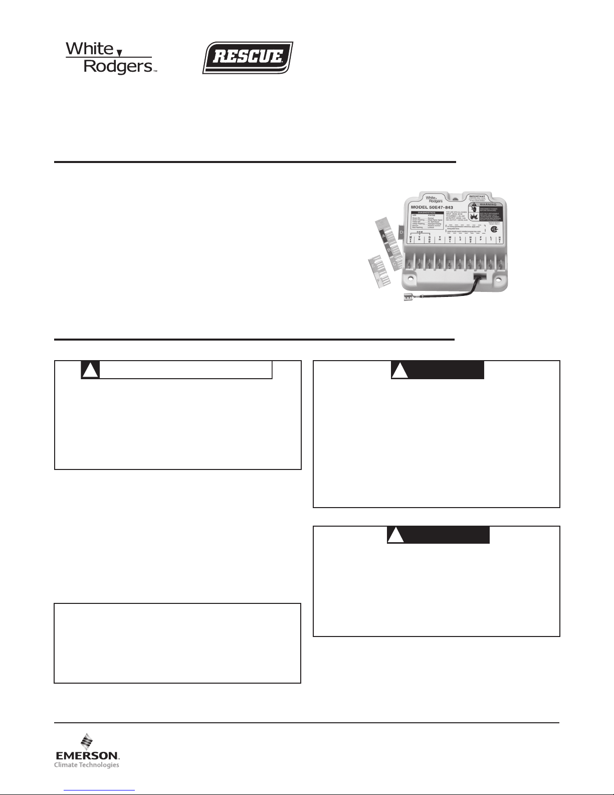
CrossReference(37-7209).Installtheselectedprogramkeyin
the slot on the left side of the module (see figure 4 on page 3).
If the module you are replacing is not listed in the Cross
Reference, contact the manufacturer of the appliance for a
recommended replacement or retrofit.
Afterinsertingtheproperprogramkey,disposeofthe
remainingkeystoensurethecorrectkeyremainsinthe
module.
Reversal of gas valve leads or open connection to MV1 and
MV2maycausecontroltolockout.Seetroubleshootingguide
for remedy.
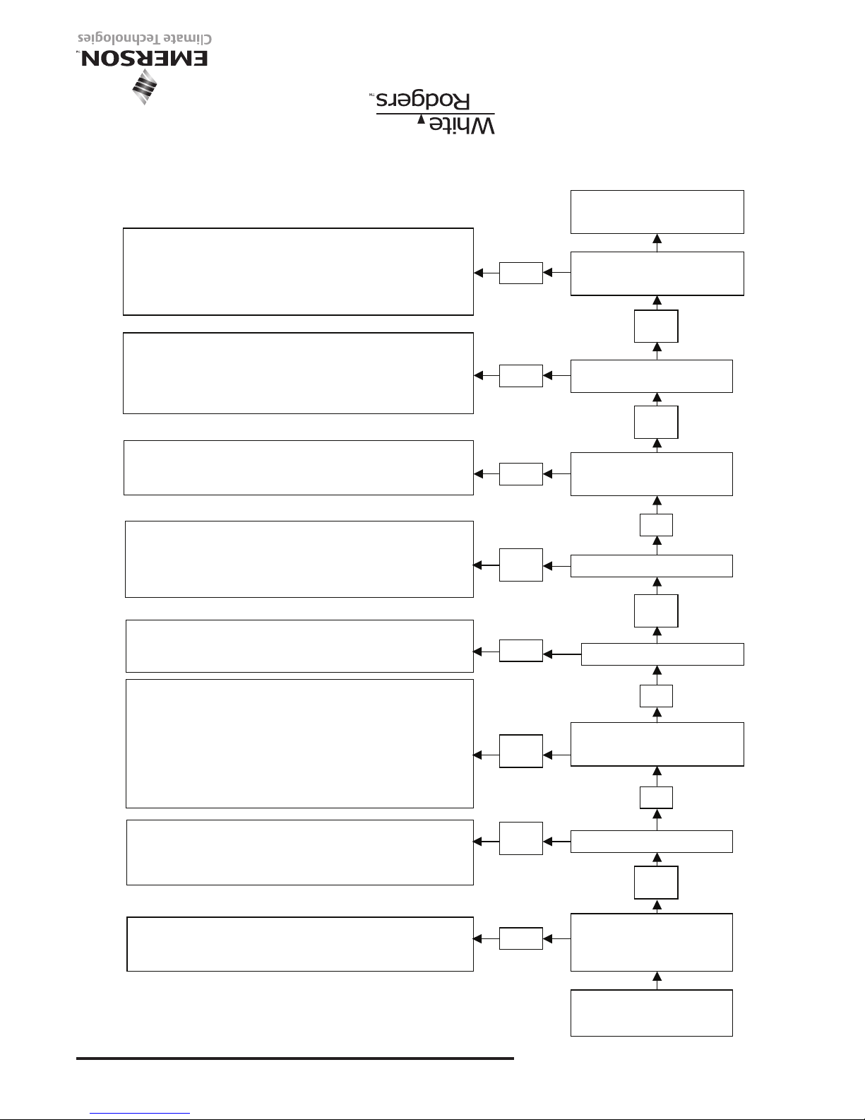
OPERATION
TROUBLESHOOTING
TYPICAL FURNACE INSTALLATION
Inatypicalapplicationthe50E47-843isdesignedtoenergize
the ignitor and gas valve and monitor the flame sensor. It
isa100%shutoffdesignthatlocksoutthegasvalveifthe
burner does not light within the trial for ignition period. The
ignitionsequencebeginswithacallforheatfromtheroom
thermostat. The thermostat applies power to the control.
Afterpre-purgeinterval,theignitorwarmsupfortheselected
time.Thecontrolenergizesthegasvalvefortheselected
trial for ignition period. If the burner lights within the allowed
period the gas valve will remain open until the call for heat
is satisfied. During the trial for ignition period the ignitor is
turned off. If the burner does not light, the control will either
gointolockoutormaketwomoreignitionretriesdepending
ontheoptionsselected.Thecontrolcanberesetfromlockout
by cycling the thermostat to remove power for a minimum of
3seconds.Itincludesasystemanalysis/troubleshootingLED
thatindicatesnormaloperation,lockout,weakamesignalor
internal control fault.
For proper control operation, the control must be electrically
connected to the gas valve and all the ignitor wiring connec-
torspluggedin.Gasvalveswithanelectric"ON/OFF"switch
must have the switch set to "ON".
The light on the control provides a self-diagnosis indication.
If the red light on the module is on continuously, the fault is
likelytobeinternaltothemodule.Tomakesure,interrupt
the line or 24 volt thermostat power for a few seconds and
then restore. If the internal fault is indicated again, and flame
sensorisnotshortedtoground,replacethecontrol.Aash-
inglightindicatestheproblemismostlikelyintheexternal
components or wiring (see chart below). Proceed as follows:
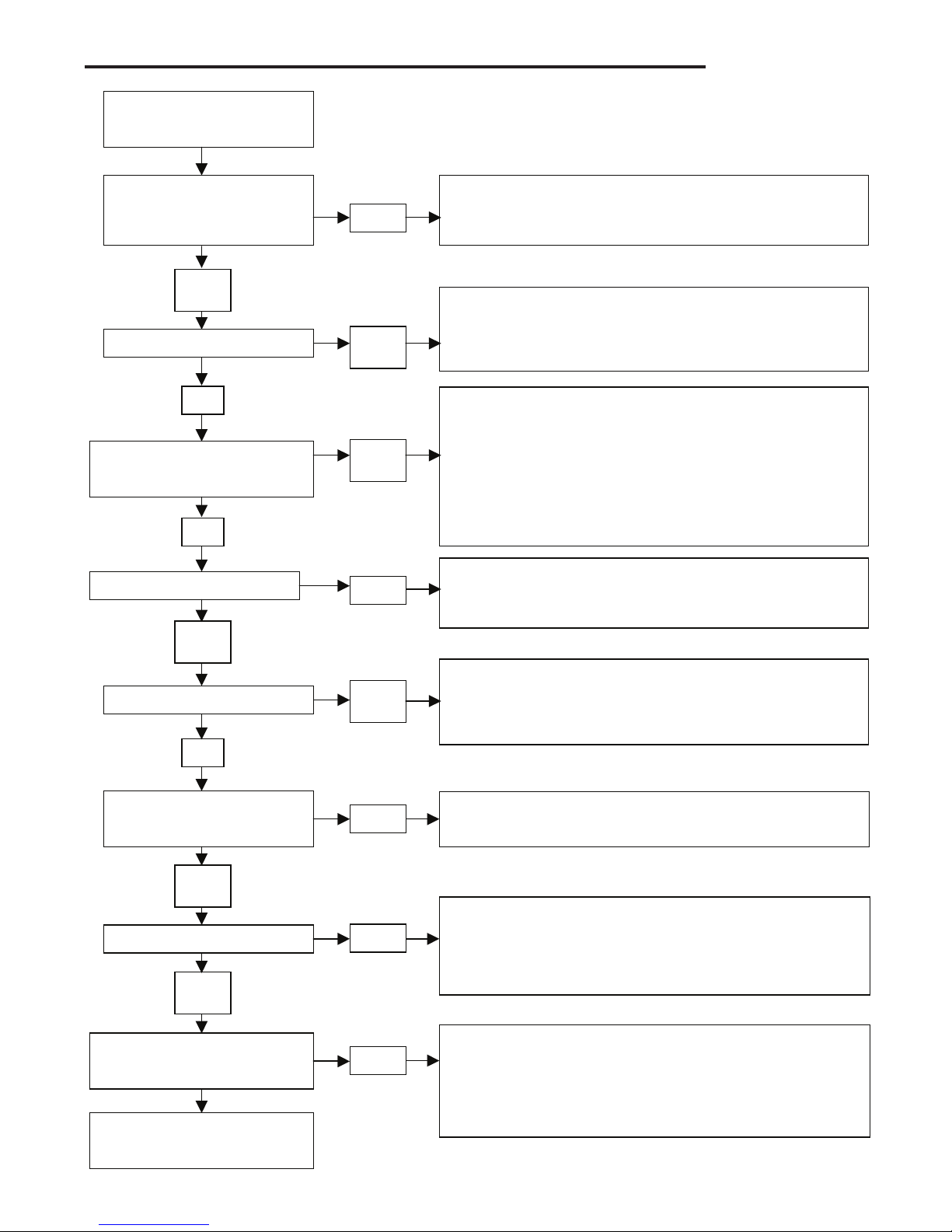
Threevisualchecks
1. The ignitor will warm up and glow red
2. The main burner flame will ignite
3. The main burner flame will continue to burn after the
ignitor is turned off
Troubleshootingthesystemconsistsofcheckingforthese
three visual indications. The chart on the next page defines
the proper action if any of these indications do not occur.
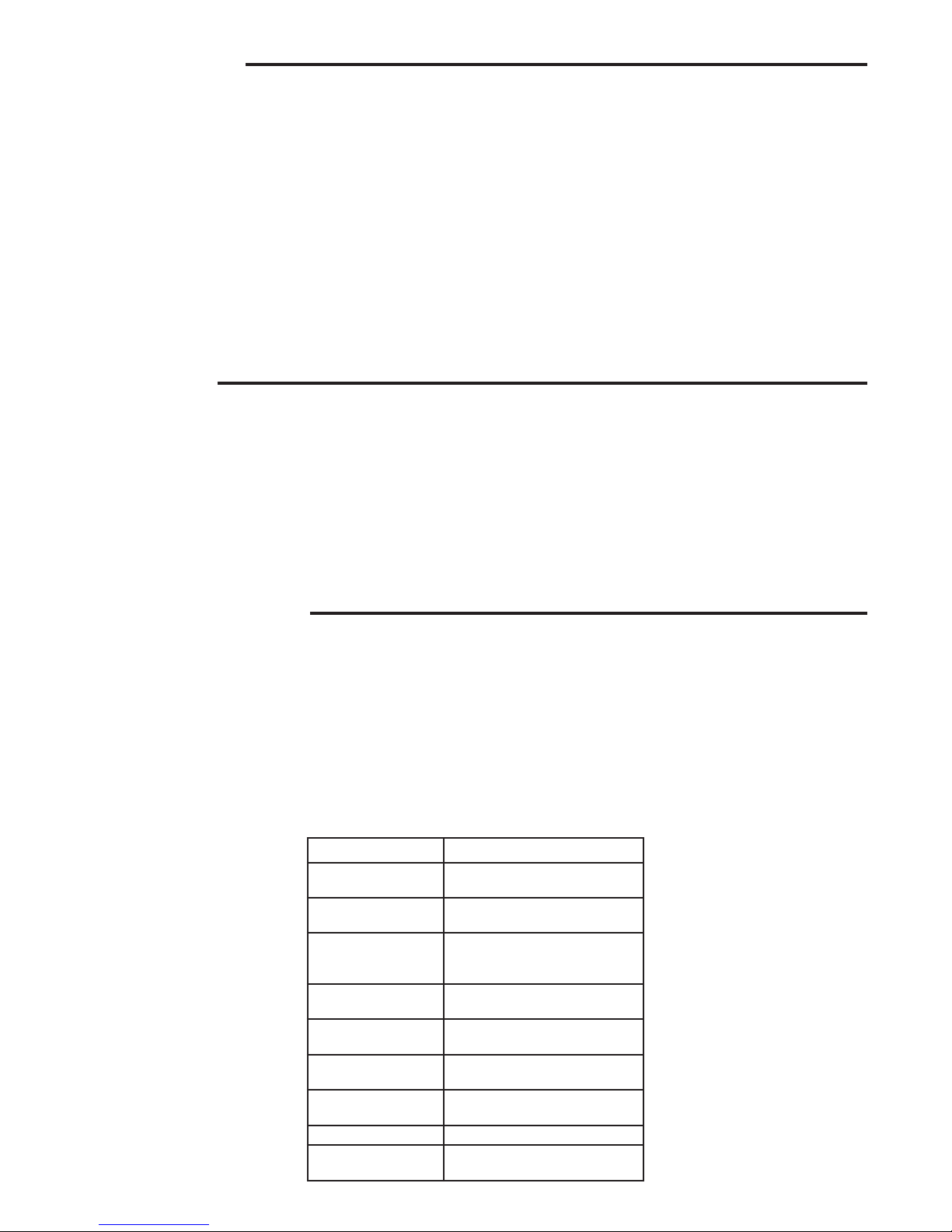
LED Condition
Green
Solid On
Normal
Green
Rapid Flashing
Weakamesignal
Red
Rapid Flash
Controlinlockout
Flame sensed when
there should be none
Red
1 Flash
Controlinlockout
Ignition retries exceeded
Red
2 Flash
Controlinlockout
Ignition recycles exceeded
Yellow
Solid On
Internalselfcheck
Yellow
Rapid Flashing
Improper Polarity
OFF Internal Failure
Red
Solid On
Gasvalvemiswiredor
Internal error detected