manuals.online logo
Brands
  1. Home
  2. •
  3. Brands
  4. •
  5. WHITECROFT LIGHTING
  6. •
  7. Lantern
  8. •
  9. WHITECROFT LIGHTING Avenue Metro Suspended User manual

WHITECROFT LIGHTING Avenue Metro Suspended User manual

Whitecroft Lighting Limited
Burlington Street, Ashton-under-Lyne, Lancashire OL7 0AX
Telephone +44 (0)161 330 6811Facsimile: +44 (0)161 331 5855
www.whitecroftlighting.com
Registered No. 3848973 England Registered Office: As above
Avenue Metro
Suspended and Surface
Installation Instructions
Revision 4 AUG 2019
PK/AVMET-INSTSUS
SPECIFICATION
Materials Polycarbonate Diffuser
Polycarbonate Optic Pods (White RAL 9003 or Black)
Aluminium Extrusion (Textured Paint - Metallic Silver, White RAL 9003 or
Black)
Supply 240V Operating temp -5˚c to 25˚c
Power Refer to Whitecroft Lighting Website for full list of power information.
Connection Terminal block 0.75mm² to 2.5mm²
Ingress protection IP20
Installation 2m, 3m and corner fittings require 2 people to install.
DIMENSIONS
Version L H W KG KG (EM) INFILL
1000mm 1000 100 80 3.5 4.0 3.0
1250mm 1250 100 80 4.5 5.0 3.5
1500mm 1500 100 80 5.0 5.5 4.5
2000mm 2000 100 80 7.0 7.5 6.0
3000mm 3000 100 80 10.0 10.5 N/A
Corner 5202100 80 4.0 N/A 3.0
GENERAL INFORMATION
1) A qualified electrician, in accordance with IEE wiring regulations should carry out
connection to mains wiring.
2) Ensure that the rated voltage and frequency requirements are compatible with the
available mains supply.
3) Do not carry out high voltage insulation test, i.e. 500/1000v this may damage internal
components.
4) Access for connection of the emergency batteries is done by lowering the geartray and
connecting the batteries to the inverter. This is to be done when a power supply is
connected. TECHNICAL SUPPORT
Telephone: 0161 331 5700
E-mail: technical@whitecroftlight.com
http://www.whitecroftlighting.com/
8
Suspended/Surface Pod Optic, Prism/Diff & Infills for Straight and Corner
sections
1. Unpack and check the contents for any damage.
2. Remove diffuser/pods/Infill and place in a dust free area. The infill will require
the earth tag and safety hooks unclipping.
3. Suspension Mounting Option part code (AOSUSKIT)
a. Fix ceiling rose centres as below. Feeding the suspension cable through the
cap. Two suspension points per straight length and one for a corner fitting.
b. Assemble clutch to suspension bracket with M4 nut.
Ensure clutch wire exit hole is at 45° so wire feeds down channel.
c. Slide bracket into hook feature on extrusion and
secure with screw. Making sure orientation is correct so the screw
lines up with hole. Note: Position can be moved but won’t be fixed.
d. Lift the fitting and feed the cable through the clutch.
e. Any access cable can be located in channel of extrusion.
f. Use spirit level when adjusting the clutch.
g. If continuous run repeat a-f.
h. For Straight continuous products the
alignment bracket and cam will be
needed. Part code (AOCMOKIT).
Supplied separately.
Make sure the pip on the cam bracket
is aligned with the dimple in the round
cut out as shown. Slide the bracket half
into the body on the hook side with the ‘U’ shape
positioned as shown.
i. For Corner fittings allow to hang from one suspension. Use the alignment
bracket and screws supplied with the continuous mounting kit –AOCMOKT.
Discard the CAM. With the gear tray of the adjacent fittings dropped (step
4g), slide the alignment bracket into one of the adjacent fittings and secure
using two of the screws supplied. Slide the other alignment bracket into the
other adjacent fitting but do not secure with screws. See 4e for image.
4. Surface Mounting Option part code AOSMOKIT (supplied as a separate item)
a. Fix surface bracket to ceiling using below guide (screws not supplied), two
brackets required for straight fittings and one for a corner fitting.
Orientation is important so follow images. All brackets face same way.
b. For all fittings slide hook bracket onto the extrusion and align with the oval
hole as shown below. Use the M4x6mm screw and serrated washer to
secure in place. Make sure that the ends of the hook are in line with the
edge of the oval hole. This is important.
c. The hook is designed to slide into the
slot feature on the ceiling bracket.
d. Lift the fittings up onto the ceiling
brackets and slide the hook into
the slot until it stops. For continuous/
corner sections as this happens the
open end of the fitting will slide onto the
alignment bracket from steps 4 e/f.
For corner fitting slide the unsecured
alignment bracket across to bridge the
fittings. Note the fitting is still
moveable at this point and care
should be taken until the final fix is
complete.
e. For Straight continuous products the
alignment bracket and cam will be
needed. Part code AOCMOKIT.
(supplied separately).
i.Make sure the pip on the cam bracket
Is aligned with the dimple in the round
cut out as shown.
ii. Slide the bracket half into the body
on the hook side with the ‘U’ shape
positioned as shown.
2
3
Straight fitting
Corner fitting
4
f. For Corner Sections use the alignment bracket and screws supplied with
the continuous kit AOCMOKIT. Discard the CAM. With the gear tray of the
adjacent fittings dropped, slide the alignment bracket into one of the
adjacent fittings and secure using two of the screws supplied.
Slide the other alignment bracket into the other adjacent fitting but do not
secure with screws. The secured alignment bracket should be inline with
the suspension or ceiling bracket.
Remove the gear tray assembly using
three No. 2 pozi screwdrivers. Ensure the
screw driver pushes fully in to take the
weight off the geartray. Be careful not to
touch the LED,s. This step is not required for
infills.
g. For Surface. Use the M5x20mm screw to
lock the body to the ceiling bracket.
5. Continuous/corner fitting.
a. For Corner fitting –hold the fittings together
and fit the remain screws to secure in place.
b. For Continuous straight fittings - turn the
cam using a 8mm flat screwdriver to clamp
the fittings together.
c. Place the foil tape provided on indicated
areas in black to
prevent light spill on both sides.
6. On standalone or continuous end of run fittings, endcaps will need installing.
Push endcap onto extrusion applying pressure when fixing with screws.
Once the endcap is installed cut the foil provided to shape and apply foil to the
black areas shown.
7. Electrical Connection (incoming)
Fixed Output DALI with
Standard
Emergency
DALI Fixed Output
with
Emergency
COMEPS
Fixed Output DALI with
Standard Emergency
Emergency COMEPS
8. Through Cable Connection.
Standalone options.
Through cable is redundant and should be ducted away neatly. Do not remove
terminal blocks.
For incoming cables use the
strain relief assembly as shown
right.
5
6
10
9. Through Cable Connection. Continue…
Continuous Straight Options.
For continuous options remove the two blank terminal blocks from the end of the
looms and feed the loom through to the next fitting geartray and then terminate the
loom wires as below.
Corner Options.
Through cabling can be removed from the terminal blocks at either end of the corner
fitting by pushing the levels down. This allows for the fitting to adapt to left or right
turns. Use the above diagram when connecting to the next fitting. ENSURE ALL
CABLES ARE HOME IF LEVER HAS BEEN PRESSED ON TERMINAL BLOCK!
10. Geartray Replacement.
Reconnect the geartray to the body by pushing upwards until the clips engage
with the body. Be careful not to touch or apply pressure to the LED’s.
7
6
11. Replacement of the diffuser, pods and infills can now be done.
Diffuser –On longer continuous runs the last diffuser may have to be trimmed.
The cut end will go into the space within the endcap.
Pods –The pods snap back in the same orientation as they were removed. This is
important as they interlock with one another and must be placed end to end in the
same orientation. Note the orientation of the emergency pod with the light tube that
lines up with the emergency indicator on the geartray.
The Organic Response Sensor option has a special short pod that sits next to the
sensor bracket.
7

This manual suits for next models

1

Other WHITECROFT LIGHTING Lantern manuals

WHITECROFT LIGHTING Aerial Industry User manual

WHITECROFT LIGHTING

WHITECROFT LIGHTING Aerial Industry User manual

WHITECROFT LIGHTING Cygnus SX Manual

WHITECROFT LIGHTING

WHITECROFT LIGHTING Cygnus SX Manual

WHITECROFT LIGHTING Aerial Industry User manual

WHITECROFT LIGHTING

WHITECROFT LIGHTING Aerial Industry User manual

WHITECROFT LIGHTING Cygnus SY User manual

WHITECROFT LIGHTING

WHITECROFT LIGHTING Cygnus SY User manual

WHITECROFT LIGHTING Aerial Industry User manual

WHITECROFT LIGHTING

WHITECROFT LIGHTING Aerial Industry User manual

WHITECROFT LIGHTING Foil SRD Manual

WHITECROFT LIGHTING

WHITECROFT LIGHTING Foil SRD Manual

WHITECROFT LIGHTING Florin E3 Series Manual

WHITECROFT LIGHTING

WHITECROFT LIGHTING Florin E3 Series Manual

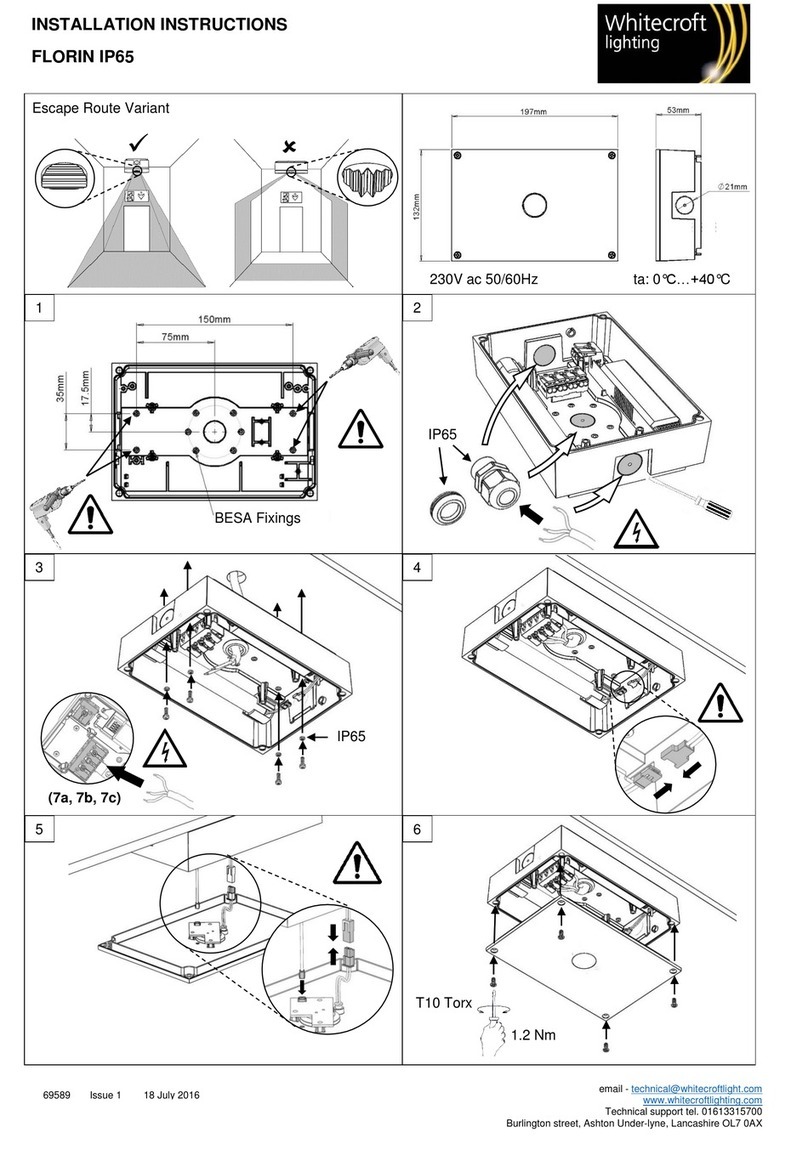
WHITECROFT LIGHTING Florin IP65 User manual

WHITECROFT LIGHTING

WHITECROFT LIGHTING Florin IP65 User manual

WHITECROFT LIGHTING ACL INDUSTRY Manual

WHITECROFT LIGHTING

WHITECROFT LIGHTING ACL INDUSTRY Manual

WHITECROFT LIGHTING TEGAN SLIM 600SQ User manual

WHITECROFT LIGHTING

WHITECROFT LIGHTING TEGAN SLIM 600SQ User manual

Popular Lantern manuals by other brands

DS Produkte TRF18P0752-1 instructions

DS Produkte

DS Produkte TRF18P0752-1 instructions

Stahl ECOLUX 6610 Series operating instructions

Stahl

Stahl ECOLUX 6610 Series operating instructions

SNOWJOE SUNJOE 24V-LGT500-CT Operator's manual

SNOWJOE

SNOWJOE SUNJOE 24V-LGT500-CT Operator's manual

PRG VARI LITE VL5 Service manual

PRG

PRG VARI LITE VL5 Service manual

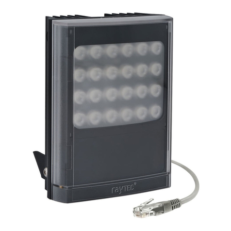
Raytec VARIO2 series installation guide

Raytec

Raytec VARIO2 series installation guide

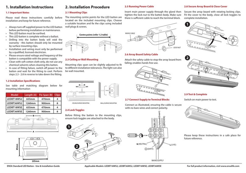
ENSA LEDBT18WS2 installation instructions

ENSA

ENSA LEDBT18WS2 installation instructions

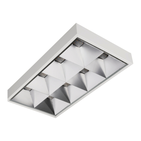
LUG OFFICE LB LED N/T Installation instruction

LUG

LUG OFFICE LB LED N/T Installation instruction

Draper RLEDL19/B instructions

Draper

Draper RLEDL19/B instructions

Green Lighting TRI-SENSOR GL4612LU Assembly & fitting instructions

Green Lighting

Green Lighting TRI-SENSOR GL4612LU Assembly & fitting instructions

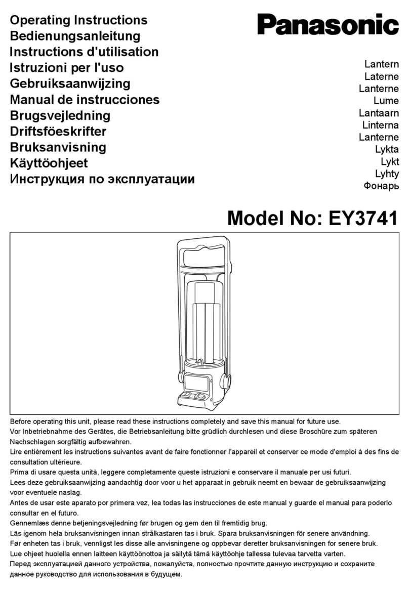
Panasonic EY3741B57 operating instructions

Panasonic

Panasonic EY3741B57 operating instructions

Clas Ohlson LCC8T instruction manual

Clas Ohlson

Clas Ohlson LCC8T instruction manual

Coolon WDN-140 manual

Coolon

Coolon WDN-140 manual

shada 1000436 instruction manual

shada

shada 1000436 instruction manual

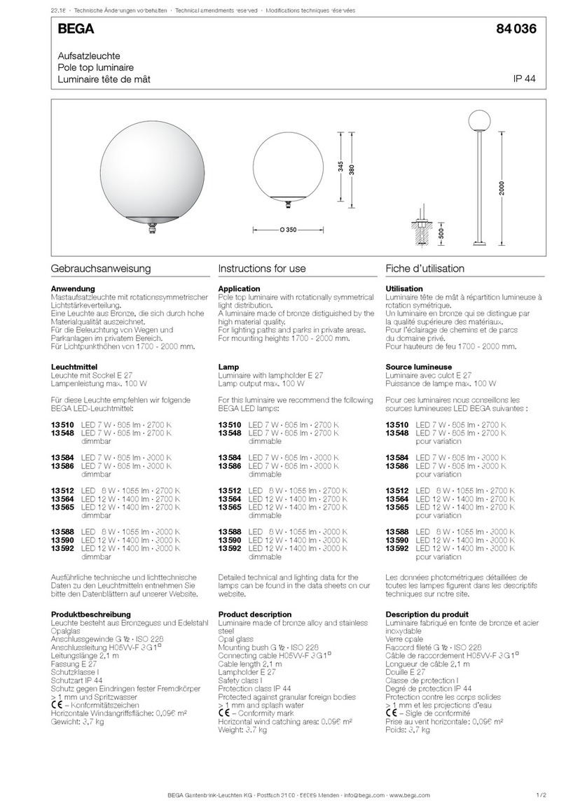
BEGA 84 036 Instructions for use

BEGA

BEGA 84 036 Instructions for use

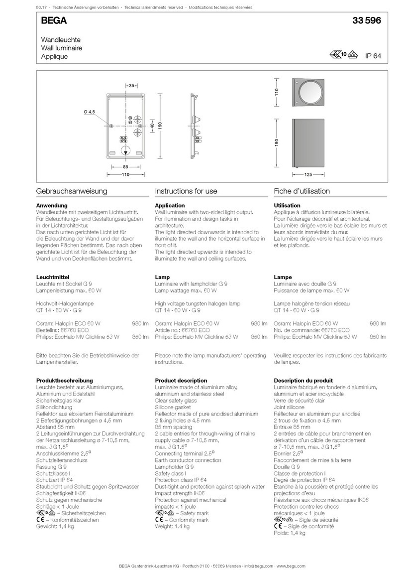
BEGA 33 596 Instructions for use

BEGA

BEGA 33 596 Instructions for use

Dale Tiffany GT701162 Assembly instructions

Dale Tiffany

Dale Tiffany GT701162 Assembly instructions

Wagan Brite Nite Pop-Up USB Lantern user manual

Wagan

Wagan Brite Nite Pop-Up USB Lantern user manual

Eaton Crouse-Hinds Pauluhn DLLA M2 Series Installation & maintenance information

Eaton

Eaton Crouse-Hinds Pauluhn DLLA M2 Series Installation & maintenance information

manuals.online logo
manuals.online logoBrands
  • About & Mission
  • Contact us
  • Privacy Policy
  • Terms and Conditions

Copyright 2025 Manuals.Online. All Rights Reserved.