INSTALLATION MANUAL
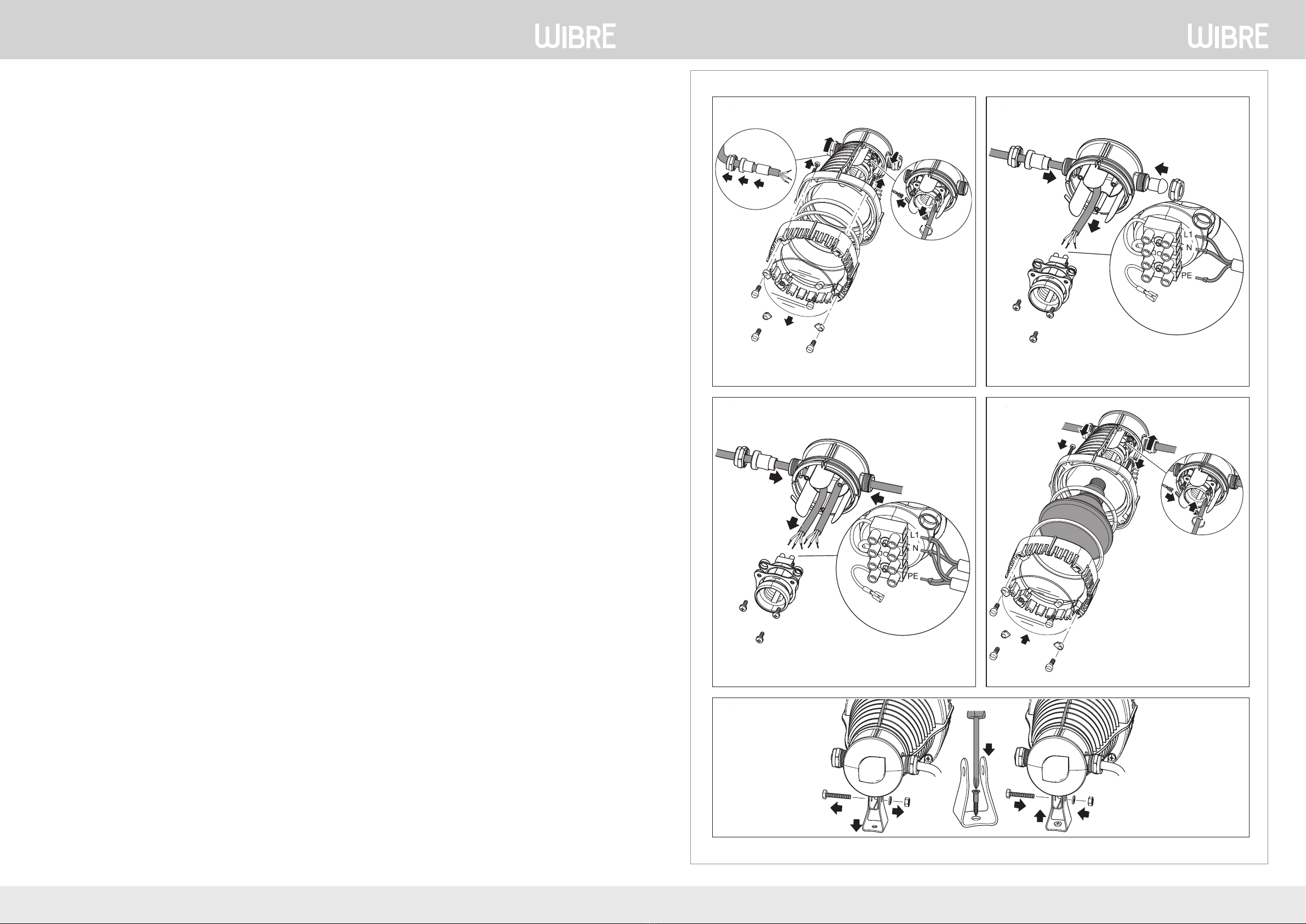
A B
C D
E
Elektrischer Anschluss
Achtung! Gefahr elektrischer Stromschläge. Der Einsatz des Gerätes unter Wasser ist ausschließ-
lich mit einer Nennspannung von 12 Volt und niemals mit 230 Volt zulässig! Der Einsatz des
Gerätes über Wasser ist mit einer Nennspannung von 230 Volt zulässig. Der elektrische Anschluss,
die Montage und Inbetriebnahme darf gemäß der EVU und VDE nur durch einen autorisierten Fachmann
durchgeführt werden. Für alle Installationen gilt die VDE 0100 Teil 702. Abweichung der Nennspannung
+6% und -10%. Der Einsatz des Gerätes unter Wasser ist ausschließlich mit einer Nennspannung von 12
Volt und niemals mit 230 Volt zulässig! Ein entsprechender Sicherheitstransformator ist zu verwenden.
Das Zuleitungskabel muss einen Querschnitt von mindestens 2,5 mm2 und darf eine maximale Länge von
5 Metern haben. Der Einsatz des Gerätes über Wasser ist mit einer Nennspannung von 230 Volt zulässig.
Das Zuleitungskabel muss einen Querschnitt von mindestens
1,5 mm2 und darf eine maximale Länge von 10 Metern haben.
Aufstellen und Inbetriebnahme (A-E)
Das Gerät wird ohne Leuchtmittel und ohne Zuleitungskabel fertig montiert geliefert. (A) Lösen Sie die
vier Schrauben M5x35 und nehmen Sie das Gehäuseoberteil ab. Im Gehäuseinnern den Kabelschuh
des Massekabels vom Erdungsblech abziehen, den Fassungshalter lösen und die Fassung dem Gehäuse
entnehmen. Überwurfmuttern PG16 lösen und Kabeltüllen entfernen. Bei 12-Volt-Betrieb Kabeltülle(n)
außen und Überwurfmutter(n) PG16 auf Zuleitungskabel HO7RN-F 3 G 2,5 mm2 Ø schieben, bei 230-
Volt-Betrieb Kabeltülle(n) innen und außen und Überwurfmutter(n) PG16 auf Zuleitungskabel HO7RN-F
3 G 1,5 mm2 Ø schieben. Bei Einzelbetrieb (B) des Gerätes das Zuleitungskabel durch die Kabeldurchfüh-
rung in das Gehäuseunterteil einführen und die nicht benötigte Kabeldurchführung mit Dichtstopfen ver-
schließen und Überwurfmutter PG16 aufschrauben, bei Betrieb mehrerer Geräte in Parallelschaltung (C)
die Zuleitungskabel durch die Kabeldurchführungen in das Gehäuseunterteil einführen. Aderendhülsen
auf Aderenden aufbringen und diese an 4-polige Klemme anschließen. (D) Die Zuleitungskabel aus dem
Gehäuse zurückziehen, bis Fassung und Fassungshalter mit dem Gehäuseunterteil verschraubt werden
können (auf richtige Positionierung achten), den Kabelschuh des Massekabels auf das Erdungsblech
aufschieben. O-Ring 98x7,5 in das Gehäuseunterteil einlegen, das Leuchtmittel einschrauben, O-Ring
110x6 in das Gehäuseoberteil einlegen und dieses mit Schrauben M5x35 wieder montieren. Kabeltüllen
in Kabeldurchführung(en) des Gehäuseunterteils schieben und mit Überwurfmutter(n) PG16 xieren.
(E) Schraube M6 und Mutter M6 lösen und Fuß von Halteringen abziehen, den Fuß mittels einer 6 mm
Schraubverbindung auf festem Grund montieren, und zwar so, dass das Gerät für niemanden eine Gefahr
darstellt und ohne Werkzeug nicht demontiert werden kann (ortsfeste Montage). Gerät mit Schraube M6
und Mutter M6 am Fuß befestigen, auf sicheren Stand achten. Stromzufuhr einschalten und die Funktion
des Scheinwerfers kontrollieren.
Montage von Farbscheibe oder Sicherheitsglas (optional)
Die Farbscheibe (a = blau, b = gelb, c = grün, d = rot,) bzw. das Sicherheitsglas (e) in die entsprechende
Aussparung des Gehäuseoberteils legen und mit vier Halteelementen und Schrauben 5x10 xieren.
Auswechseln des Leuchtmittels
Sicherheitshinweise zuvor beachten! Stromzuführung unterbrechen und gegen Wiedereinschalten si-
chern. Der Lampensockel (E 27) kann sowohl 12 Volt- als auch 230 Volt-Leuchtmittel PAR 38 aufnehmen.
Der Einsatz des Gerätes unter Wasser ist ausschließlich mit einer Nennspannung von 12 Volt und niemals
mit 230 Volt zulässig! Verwenden Sie das entsprechende Original-Leuchtmittel PAR 38 12 V/ 100 W der
Firma WIBRE. Der Einsatz des Gerätes über Wasser ist mit einer Nennspannung von 230 Volt zulässig!
Verwenden Sie das entsprechende Original-Leuchtmittel PAR 38 230 V/120 W der Firma WIBRE. Lösen Sie
die vier Schrauben M5x35 und nehmen Sie das Gehäuseoberteil ab. Beachten Sie, dass keine Feuchtigkeit
in das Gerät gelangt. Leuchtmittel und O-Ringe ersetzen, Gehäuseoberteil wieder montieren. Netzan-
schluss wiederherstellen und Funktion überprüfen. Wichtig! Es dürfen nur Original-Leuchtmittel der
Firma WIBRE verwendet werden.
Verschleißteile
Leuchtmittel und Dichtringe sind Verschleißteile und unterliegen nicht der Gewährleistung.
Reinigung
Sicherheitshinweise zuvor beachten! Führen Sie die Arbeitsschritte gemäß Auswechseln des Leuchtmit-
tels durch. Verwenden Sie nur Wasser und eine weiche Bürste. Beachten Sie, dass keine Feuchtigkeit in
das Gerät gelangt.
Reparatur
Das Gerät ist bei Beschädigung des Gehäuses nicht reparaturfähig und muss deshalb entsorgt werden.
Entsorgung
Das Gerät ist gemäß den nationalen gesetzlichen Bestimmungen zu entsorgen. Fragen Sie Ihren
Fachhändler.
Störungen
Störung Ursache Abhilfe
Lampe leuchtet nicht Stromzuführung unterbrochen Stromzuführung kontrollieren
Leuchtmittel kontrollieren und ggf.
wechseln, Kontakte reinigen
Leuchtleistung lässt nach Lampenglas verschmutzt Reinigung
Wasser im Scheinwerfer Dichtung defekt Dichtung kontrollieren und erneuern
Electrical connection
Attention! Danger of electric shock. The use of the unit under water is only permissible with a 12
Volt rated voltage, never connect to 230 Volt! The use of the unit out of the water is permissible
with a rated voltage of 230 Volt.
Only entrust an authorised expert to carry out the electrical connection, installation and start-up in accordance
with the German EVU and VDE. The VDE 0100, part 702, are valid for all installations. Deviations from the rated
voltage +6% and -10%. The use of the unit under water is only permissible with a 12 Volt rated voltage, never
connect to 230 Volt! Use a corresponding safety transformer. Ensure that the supply cable has a minimum cross
section of 2.5 mm2, its maximum length is 5 metres. The use of the unit out of the water is permissible with a rated
voltage of 230 Volt. Ensure that the supply cable has a minimum cross section of 1.5 mm2, its maximum length is
10 metres.
Set-up and start-up (A-E)
The unit comes fully assembled, but without bulbs and supply cable. (A) Undo the four M5x35 screws and
remove the upper section of the housing. Inside the housing, disconnect the cable shoe of the mass cable from the
earthing plate, detach the socket holder and remove the socket from the housing. Undo the union nuts PG16 and
remove the cable sheaths. For a 12 Volt operation, slide the outer cable sheath(s) and the union nut(s) PG16 on
the HO7RNF 3 G 2.5mm2 Ø supply cable; for a 230 Volt operation, slide the internal and external cable sheath(s)
and the union nut(s) PG16 on the HO7RN-F 3 G 1.5 mm2 Ø supply cable. When the unit is operated on its own (B),
insert the supply cable into the bottom section of the housing through the cable lead-through, close the non re-
quired cable leadthrough using the plug, and screw on union nut PG16; if several units are circuited in parallel (C),
insert the supply cable into the bottom part of the housing through the cable leadthroughs. Affix the ferrules to
the conductor ends and connect to the 4 pole terminal. (D) Pull the supply cables back from the housing until the
socket and the socket holder can be screwconnected to the bottom section of the housing (ensure correct positio-
ning), slide the cable shoe of the mass cable onto the earthing plate. Insert the 98x7.5 O ring in the bottom section
of the housing, screw in the bulb, insert the 110x6 O ring in the upper section of the housing and refit same using
M5x35 screws.Insert the cable sheaths in the cable leadthrough(s) of the bottom section of the housing and fix
using union nut(s) PG16. (E) Undo screw M6 and nut M6 and remove the foot from the retaining rings, fit the foot
on firm ground using a 6 mm screw connection so as to ensure that the unit presents no danger for anybody and
cannot be disassembled without tools (permanent local installation). Fasten the unit to the foot using an M6 screw
and an M6 nut and ensure firm seating. Connect the power supply and check the spotlight function.
Fitting a coloured glass or safety glass (optional)
Insert the coloured glass (a = blue, b = yellow, c = green, d = red,) or the safety glass (e) in the corresponding
recess in the upper section of the housing and fix using four retaining elements and 5x10 screws.
Exchanging the bulb
Adhere to the safety information given above! Disconnect the power supply and take measures to prevent
unintentional switching on. Both 12 Volt and 230 Volt PAR 38 bulbs fit in the lamp base (E 27). The use of the unit
under water is only permissible with a 12 Volt rated voltage, never connect to 230 Volt! Use the appropriate original
bulb PAR 38 12 V/ 100 W from WIBRE. The use of the unit out of the water is permissible with a rated voltage of
230 Volt! Use the appropriate original bulb PAR 38 230 V/ 120 W from WIBRE. Undo the four M5x35 screws and
remove the upper section of the housing. Ensure that no moisture can enter the unit. Replace bulb and O rings, refit
the upper section of the housing. Reconnect to the power supply and check function. Important! Only original
bulbs from WIBRE may be used.
Wearing parts
Bulbs and sealing rings are wear parts and are excluded from the warranty.
Cleaning
Adhere to the safety information given above! Carry out the steps as specified under ‚Replacing the bulbs‘. Only use
water and a soft brush. Ensure that no moisture can enter the unit.
Repair
In the event of damage of the housing, the unit cannot be repaired and, therefore, has to be disposed of.
Disposal
Dispose of the unit in accordance with the national legal regulations.
Malfunctions
Trouble shooting Cause Remedy
Lamp does not light up Power supply interrupted Check power supply
Check bulb, replace, if necessary
Clean contacts
Light intensity decreases Lamp glass soiled Cleaning
Water in the spotlight Seal defective Check and replace seal
2/4 WIBRE Elektrogeräte Edmund Breuninger GmbH & Co. KG · Liebigstrasse 9 · 74211 Leingarten/Germany
T
elefon: +49 (0) 7131 9053-0 · T
elefax: +49 (0) 7131 9053-19 · E-Mail:
[email protected]INSTALLATION MANUAL
WIBRE Elektrogeräte Edmund Breuninger GmbH & Co. KG · Liebigstrasse 9 · 74211 Leingarten/Germany
T
elefon: +49 (0) 7131 9053-0 · T
elefax: +49 (0) 7131 9053-19 · E-Mail:
[email protected] 3/4


