Wibre 4.0492 User manual

INSTALLATION · MANUAL
4.0492
Schwimmbad-Scheinwerfer
Swimmingpool-Light
Projecteur de piscine
1. Anwendung
Einbau-Unterwasser-Scheinwerfer zur Beleuchtung von großen
Schwimmbädern undWettkampfbecken.
Der Scheinwerfer ist für einen Einsatz bis 5,0 m Wassertiefe geeignet.
Die Konstruktion ist komplett ausV4A-Edelstahl 1.4571 gefertigt und
zusätzlich epoliert. Die Verwendung des Scheinwerfers in Süßwasser,
chloriertem Schwimmbadwasser und in Meerwasser ist möglich.
Scheinwerfer ist vor Einfrieren zu schützen, das Wasser muss frei von
Metall angreifenden Bestandteilen sein.
Einbaugehäuse ist zur Installation erforderlich und ist je nach Einbau-
art auszuwählen,
Zubehörteile (z.B. Betriebsgeräte) sind optional lieferbar.
Achtung! Betrieb nur Unterwasser bis zu einerWassertemperatur
max. 35°C. Angeschlossene Spezialkabel sind nicht zu entfernen oder
zu kürzen, längere Kabellängen >5 m lieferbar.
Von jeglichen Kabelverbindungen im Einbaugehäuse bzw. im Kabel-
rohr wird abgeraten.
Für die gesamte lichttechnische Anlage wird eine Überspannungs-
schutzeinheit und die Verwendung eines Trenntrafos zur sicheren
elektrischen Trennung (Schutztrennung) empfohlen. Beim Montage
sollte auf ausreichend ESD-Schutz geachtet werden.
Sonderkonstruktionen-/anwendungen auf Anfrage.
2. Technische Daten/Konstruktion
· Schutzart IP68 – Wassertiefe bis 5 m
· Komplett ausV4A-Edelstahl 1.4571, epoliert
· runde Aufsatzblende ausV4A-Edelstahl, Höhe 5 mm
· POW-LED weiß 12 V-DC dimmbar
· temperaturüberwacht (onboard)
· Überspannungsschutz
· speziell für Schwimmbadausleuchtung angepasste Lichtverteilung
„asymmetrisch Mixflux“
· Konstantstromnetzteil/RGB Controller separat bestellen
· Einbaugehäuse ausV4A-Edelstahl mit 1,5 m Kabelschutzrohr
· Lieferung mit 5 m Spezial-Unterwasserkabel
1. Application
Built-in underwater spotlights for illumination large swimming pools
and competition pools.
The spotlight is suitable for use down to a water depth of 5.0 m.The
structure is completely made from V4A stainless steel 1.4571 and is
electro-polished in addition. The spotlight can be used in fresh water,
chlorinated swimming pool water and salt water.
The spotlight must be protected from freezing, and the water must be
free of metal-corroding components.
An installation housing is required and must suit the installation type,
accessory parts (e.g. controllers) are available as options.
Caution! Operation only underwater up to a max. water tempe-
rature of 35°C. Connected special cables must not be removed or
shortened, longer cable lengths >5 m are available.
Cable connections in the installation housing or conduit are not re-
commended.
For the entire lighting system, a surge protection unit and use of an
insulating transformer for safe electrical disconnection (electrical
separation) are recommended. Adequate ESD protection must be
ensured during fitting.
Special designs/applications on request.
2. Technical data/Contruction
· Protection class IP68 – up to 5m water depth
· Entirely made of stainless steel 316Ti 1.4571, epolished
· Round attachment cover, made of stainless steel 316Ti, height 5 mm
· POW-LED white 12V-DC
· temperature controlled (onboard)
· surge protection
· light distribution especially for swimming pool lighting
„asymmetric Mixflux“
· Constant-current power source/RGB controller ordered separately
· Installation housing made of stainless steel 316Ti with 1.5 m
cable protection tube
· Supplied with 5 m of special underwater cable
1. Application
Projecteur subaquatique encastré pour l‘éclairage des grandes pisci-
nes et piscines de compétition.
Le projecteur convient pour l‘utilisation jusqu‘à 5,0 m de profondeur
d‘eau. La construction est complètement fabriquée en acier inoxyda-
ble V4A 1.4571 et électropolie. L‘utilisation du projecteur est possible
en eau douce, dans les piscines à eau chlorée et dans l‘eau de mer.
Protéger le projecteur contre le gel, l‘eau doit être exempte de sub-
stances agressives pour les métaux.
Le boîtier d‘encastrement est nécessaire pour l‘installation et doit être
sélectionné en fonction du type d‘encastrement ; des accessoires (par
ex. équipements) sont également disponibles en option.
Attention! Fonctionnement uniquement sous l‘eau jusqu‘à une tem-
pérature d‘eau max. de 35 °C. Les câbles spiralés raccordés ne doivent pas
être retirés ou raccourcis, longueurs de câbles > 5 m disponibles.
Toutes les connexions de câbles dans le boîtier d‘encastrement ou la
gaine de câbles sont déconseillées. Il est recommandé d‘utiliser, pour
l‘ensemble de l‘installation technique d‘éclairage, une unité de sur-
tension et un transformateur d‘isolement pour l‘isolation électrique
sûre (isolation de protection). Lors du montage, veiller à garantir une
protection suffisante contre les décharges électrostatiques.
Constructions / applications spéciales sur demande.
2. Données techniques/Construction
· Indice de protection IP68 – jusqu‘à une profondeur de 5 m
· Complet en acier inoxydable 316Ti 1.4571, e-polir
· enjoliveur rond en acier inoxydable 316Ti, hauteur 5 mm
· POW-LED blanc 12V-DC
· control de température par (onboard)
· limiteur de tension
· Diffusion de lumière adaptée spécialement à l‘éclairage des piscines
„asymmetric Mixflux“
· Bloc d‘alimentation en courant continu/Contrôlleur RVB
commander séparément
· Boîtier d‘encastrement en acier inoxydable 316Ti avec gaine de
protection pour câble de 1,5 m
· Livré avec câbles spéciaux immergeables de 5 m
WIBRE Elektrogeräte Edmund Breuninger GmbH & Co. KG · Liebigstrasse 9 · 74211 Leingarten/Germany
Telefon: +49 (0) 7131 9053-0 · Telefax: +49 (0) 7131 9053-19 · E-Mail: info@wibre.de 1/4
100
380 380
120
355
IP68
STAINLESS
STEEL V4A
1.4571
316Ti
POW-LED
INCL.
3.000 K
4.500 K
6.000 K
BLUE
CONSTANT
CURRENT
CONSTANT
VOLTAGE
CONSTANT
CURRENT
CONSTANT
VOLTAGE
ta max
35°C
CABLE
INCL.
max 5m
Symbolic Picture

INSTALLATION · MANUAL
3. Installation/Montage
Zur Installation sind die nationalen Sicherheitsvorschriften zu beachten.
Es wird keine Haftung für unsachgemäßen Einsatz oder Montage
übernommen. Bei nachträglichen Änderungen an den Leuchten wird
keine Haftung übernommen.
Montage des Scheinwerfers in Verbindung mit entsprechendem Ein-
baugehäuse aus V4A-Edelstahl mit 1,5 m Kabelschutzrohr für den
Wand- und Bodeneinbau in Betonbecken mit Fliesenauskleidung
(max. 30 mm Fliesen-/Mörtelaufbau oder nach Anfrage), Edelstahl-
becken zum Einschweißen und Becken mit Klebe-/Folienanstrich
(Klebeflansch) möglich.
Montage in Betonbecken
Einbaugehäuse (4.0492.01.00) an vorderer Verschalung (Wassersei-
te) nach Markierung ausrichten und mittels den 3 Halteelementen
fixieren. Die richtige Ausrichtung (laut Zeichung 3.2.) des Einbau-
gehäuses an der Schalwand ist für den späteren Einbau des Schein-
werfer unbedingt zu beachten. Gegebenenfalls äußeren Bund z.B.
mit Silikon abdichten um das Eindringen von Schmutz ins Innere des
Einbaugehäuses zu vermeiden. Kunststoffabschlussstück an der hin-
terenVerschalung fixieren. Das Einbaugehäuse, das Kabelschutzrohr,
die Schellen und das Kunststoffabschlussstück auf festen Halt prüfen.
3.1./3.2.
Nach dem Betonieren und Entfernen der Verschalung Mörtel und
Fliesen bis max. zum Aussendurchmesser (ø 355 mm) des Einbau-
gehäuses auftragen. Maximaler Mörtel- und Fliesenaufbau 30mm.
Bei höherem Fliesen/-Mörtelaufbau nach Absprache längere Befesti-
gungsschrauben ausV4A Edelstahl verwenden. 3.3.
Montage in Edelstahlbecken
Positionierung der Leuchten festlegen und Öffnungen von ø 357 mm
in Schwimmbeckenwand entsprechend ausschneiden. Einbaugehäuse
(4.0492.01.00) nach Markierung ausrichten und bauseits fixieren.
Kunststoffabschlussstück am Ende des Kabelschutzrohres fixieren.
Die richtige Ausrichtung (laut Zeichnung 3.2.) des Einbaugehäuses
an der Schalwand ist für den späteren Einbau des Scheinwerfer unbe-
dingt zu beachten. Einbaugehäuse, Kabelschutzrohr mit Schellen und
Kunststoffabschlussstück auf festen Halt prüfen.
Gehäuse mit der Schwimmbadwand IP68-dichtschweißen und
Schweißnaht nachträglich erneut passivieren. 3.4.
Montage in Becken mit Klebe-/Folienanstrich
Einbaugehäuse (4.0492.03.00) mit Klebeflansch an der vorderen
Verschalung (Wasserseite) nach Markierung ausrichten und fixieren.
Die richtige Ausrichtung (laut Zeichung 3.2.) des Einbaugehäuses an
der Schalwand ist für den späteren Einbau des Scheinwerfer unbedingt
zu beachten. Gegebenenfalls äußeren Bund z.B. mit Silikon abdichten um
das EindringenvonSchmutz ins Innere desEinbaugehäuses zuvermeiden.
3. Installation/Fitting
National safety regulations must be followed during installation. No
liability will be accepted for improper use or fitting. No liability will be
accepted in case of retrospective modification to the lights.
Spotlight can be fitted in conjunction with the appropriate installati-
on housing fromV4A stainless steel, with 1.5 m cable conduit for wall
and floor installation in concrete basins with tiled lining (max. 30 mm
tile/mortar layer or on request), stainless steel basins for welding in,
and basins with adhesive/film covering (adhesive flange).
Fitting in concrete basins
Align the installation housing to the front lining (water side) accor-
ding to the marking and fix using the 3 retaining elements. Correct
alignment (acc. to drawing 3.2.) of the installation housing to the
plank partition is vital for subsequent spotlight installation. If ne-
cessary, seal the outer flange, e.g. with silicon, to prevent dirt from
penetrating inside the installation housing Fix the plastic end piece to
the rear lining. Check that the installation housing, the cable conduit,
the clips and the plastic end piece are securely fixed. 3.1./3.2.
After concreting and removal of the lining, apply mortar and tiles up
to a max. outside diameter (ø 355 mm) of the installation housing.
Maximum mortar and tile layer 30mm. Thicker tile/mortar layers
upon consultation, use longer fastening screws from V4A stainless
steel. 3.3.
Installation in stainless steel basins
Determine the position of the lights and cut out corresponding ø 357
mm openings in the swimming basin wall. Align the installation hou-
sing to the markings and fix in place. Fix the plastic end piece on the
end of the cable conduit.
Correct alignment (acc. to drawing 3.2.) of the installation housing
to the plank partition is vital for subsequent spotlight installation.
Check that the installation housing, cable conduit with clips and pla-
stic end piece are securely fixed.
Seal weld the housing to the swimming pool wall to IP68 and then
passivate the weld seam. 3.4.
Installation in basins with adhesive/lm covering
Align the installation housing with adhesive flange to the front lining
(water side) according to the marking and fix. Correct alignment (acc.
to drawing 3.2.) of the installation housing to the plank partition is
vital for subsequent spotlight installation. If necessary, seal the outer
flange, e.g. with silicon, to prevent dirt from penetrating inside the
installation housing Fix the plastic end piece to the rear lining. 3.1.
Check that the installation housing and cable conduit are securely
fastened with clips and plastic end piece.
After concreting and removal of the lining, apply the adhesive/film
covering up to the inside edge of the installation housing.
3. Installation / Montage
Respecter les prescriptions de sécurité nationales pour l‘installation.
Toute responsabilité est déclinée en cas d‘utilisation ou de montage
incorrect. Toute responsabilité est déclinée en cas de modification
ultérieure des lampes.
Montage possible du projecteur en combinaison avec un boîtier
d‘encastrement correspondant en acier inoxydableV4A avec gaine de
protection des câbles de 1,5 m pour le montage encastré dans le mur
ou le sol de bassins en béton carrelés (hauteur max. carrelage / mor-
tier 30 mm ou hauteur spéciale sur demande), bassins en acier inoxy-
dable à souder et bassins à revêtement collé / liner (bride adhésive).
Montage dans des bassins en béton
Alignerle boîtier d‘encastrement sur le coffrage avant(côtéeau) selon
le repère, et le fixer au moyen de 3 éléments de fixation. L‘alignement
précis (selon le schéma 3.2.) du boîtier d‘encastrement sur le mur de
coffrage doit impérativement être respecté pour le montage ultérieur
du projecteur. Étanchéifier le collet extérieur par ex. avec du silicone le cas
échéant, de manière à éviter toute pénétration de saletés à l‘intérieur
du boîtier d‘encastrement. Fixer la pièce terminale en plastique sur le
coffrage arrière. Vérifier la bonne fixation du boîtier d‘encastrement,
de la gaine de protection des câbles, des colliers et de la pièce termi-
nale en plastique. 3.1./3.2.
Après le bétonnage et le retrait du coffrage, appliquer le mortier
et les carreaux jusqu‘au diamètre extérieur (ø 355 mm) du boîtier
d‘encastrement au maximum. Hauteur maximale mortier / carreaux
30 mm. En cas de hauteur mortier / carreaux supérieure, utiliser des
vis de fixation plus longues en acier inoxydableV4A après concertati-
on avec un spécialisteWIBRE. 3.3.
Montage dans des bassins en acier inoxydable
Définir le positionnement des éclairages et réaliser des découpes
adaptées de ø 357 mm dans la paroi du bassin. Aligner le boîtier
d‘encastrement selon le repère, et le fixer à la paroi. Fixer la pièce
terminale en plastique sur l‘extrémité de la gaine de protection des
câbles.
L‘alignement précis (selon le schéma 3.2.) du boîtier d‘encastrement
sur le mur de coffrage doit impérativement être respecté pour le
montage ultérieur du projecteur. Vérifier la bonne fixation du boîtier
d‘encastrement, de la gaine de protection des câbles avec colliers et
de la pièce terminale en plastique.
Réaliser une soudure étanche IP68 du boîtier sur la paroi du bassin,
puis passiver à nouveau le cordon de soudure ultérieurement. 3.4.
Montage dans des bassins à revêtement collé/liner
Aligner le boîtier d‘encastrement avec la bride adhésive sur le coffrage
avant (côté eau) selon le repère, et le fixer. L‘alignement précis (selon
le schéma 3.2.) du boîtier d‘encastrement sur le mur de coffrage
2/4 WIBRE Elektrogeräte Edmund Breuninger GmbH & Co. KG · Liebigstrasse 9 · 74211 Leingarten/Germany
Telefon: +49 (0) 7131 9053-0 · Telefax: +49 (0) 7131 9053-19 · E-Mail: info@wibre.de
TOP/OBEN
45°
ø 357 mm
Edelstahlwand
stainless steel wall
mur en acier
IP68
dichtgeschweißt
IP68 welded
IP68 oudé
Mörtel
mortar
mortier
Fliesen
tiles
carreaux
ø 355mm
Beton
concrete
béton
max 30 mm
Beton
concrete
béton
Klebe-/
Folienanstrich
adhesive/
foil coating
revêtement collé/
liner
Klebeflansch
adhesive flange
flasque de collage
ø 315 mm
Dichtung
Seal
Joint
3.1
3.2
3.3 3.5
3.4
Beton
concrete
béton
eingelegte Folie
fitted foil
revêtement
intérieur
Druckflansch
pressure flange
flasque de
pression
ø 315 mm
Dichtung
Seal
Joint
315 mm
ø 7 mm
Folie
foil
liner
TK 330 mm
3.6
3.7

INSTALLATION · MANUAL
Caution: The 2 fastening screw holes for subsequent spotlight
fitting must be kept free. The adhesive flange must be pre-treated
to improve adhesion if necessary. The procedure is described in the
instructions for use of the material concerned. 3.5.
Installation in basins with inlayed lm
or thin-walled basins (pressure ange)
Align the installation housing to the front lining (water side) accor-
ding to the marking and fix. Correct alignment (acc. to drawing 3.2.)
of the installation housing to the plank partition is vital for subse-
quent spotlight installation. If necessary, seal the outer flange, e.g.
with silicon, to prevent dirt from penetrating inside the installation
housing. Fix the plastic end piece to the rear lining. 3.1.
Check that the installation housing and cable conduit are securely
fastened with clips and plastic end piece.
After concreting and removal of the lining, insert the film and make
the appropriate cutout at the installation housing (14 holes 7 mm for
screws toTK 330 and 1 hole ø 315 mm for spotlight). 3.7.
Uniformly apply installation housing, seal, film, seal, pressure flange,
12 screws, prevent folds in the film and tighten cross-wise to a torque
of 2.5 Nm. 3.6.
Fitting the spotlight
Guide the UW cable cable through the inside cable fitting of the in-
stallation housing into the cable conduit and coil approx. 1.5 m of
cable in the installation housing.Tighten the cable fitting so that the
cable is sealed. 3.10.
Insert, align and tighten the spotlight. If the installation housing is
incorrectly aligned, a compensating adapter ring must be provided
(available on request)
Screw the supplied M20 plastic fitting into the plastic end piece and
tighten the gland nut so that the cable is sealed. 3.8.
Caution: Use only the factory-connected cable. Specify the
desired cable length when ordering.
Electrically connect individual connection wires to the power units in
accordance with the instructions. 3.9.
Also see the manual of the corresponding power unit or the RGBW
controller for the maximum number of lamps and connection type.
Note: For non-factory connected cable see item 4.
doit impérativement être respecté pour le montage ultérieur du pro-
jecteur. Étanchéifier le collet extérieur par ex. avec du silicone le cas
échéant, de manière à éviter toute pénétration de saletés à l‘intérieur
du boîtier d‘encastrement. Fixer la pièce terminale en plastique sur le
coffrage arrière. 3.1.
Vérifier la bonne fixation du boîtier d‘encastrement, de la gaine de protec-
tion des câbles avec colliers et de la pièce terminale en plastique.
Après le bétonnage et le retrait du coffrage, appliquer le revêtement
collé / liner jusqu‘à l‘arête intérieure du boîtier d‘encastrement.
Attention: Veiller à ne pas recouvrir les 2 trous de fixation pour
vis, pour le montage ultérieur du projecteur. La bride adhésive doit
être préparée le cas échéant, afin d‘améliorer l‘adhérence. Pour cela,
se référer aux instructions d‘utilisation du matériau utilisé. 3.5.
Montage dans des bassins avec lm intérieur
ou bassins à parois nes (bride de pression)
Alignerle boîtier d‘encastrement sur le coffrage avant(côtéeau) selon
le repère, et le fixer. L‘alignement précis (selon le schéma 3.2.) du
boîtier d‘encastrement sur le mur de coffrage doit impérativement
être respecté pour le montage ultérieur du projecteur. Étanchéifier
le collet extérieur par ex. avec du silicone le cas échéant, de ma-
nière à éviter toute pénétration de saletés à l‘intérieur du boîtier
d‘encastrement. Fixer la pièce terminale en plastique sur le coffrage
arrière. 3.1.
Vérifier la bonne fixation du boîtier d‘encastrement, de la gaine
de protection des câbles avec colliers et de la pièce terminale en
plastique.
Après le bétonnage et le retrait du coffrage, installer le film et réa-
liser l‘évidement correspondant au niveau du boîtier d‘encastrement
(14 trous de 7 mm pour les vis sur leTK 330 et 1 trou ø 315 mm pour
le projecteur). 3.7.
Installer le boîtier d‘encastrement, le joint, le film, le joint, la bride de
pression, 12 vis réparties uniformément ; éviter tous plis dans le film
et serrer les vis en croix avec un couple de 2,5 Nm. 3.6.
Montage du projecteur
Introduire le câble subaquatique dans le raccord de câble intérieur du
boîtier d‘encastrement dans la gaine de protection des câbles et en-
rouler env. 1,5 m de câble dans le boîtier d‘encastrement. Serrer fer-
mement le raccord de câble pour que le câble soit étanchéifié. 3.10.
Insérer le projecteur, l‘aligner et le visser. Si le boîtier d‘encastrement
est mal aligné, prévoir une bague adaptatrice de compensation en
option (sur demande)
Visser le raccord à vis M20 en plastique fourni sur la pièce terminale
en plastique et serrer fermement l‘écrou-raccord afin que le câble soit
étanchéifié. 3.8.
Attention: n‘utiliser que des câbles raccordés en usine. Indiquer
la longueur de câble souhaitée lors de la commande.
WIBRE Elektrogeräte Edmund Breuninger GmbH & Co. KG · Liebigstrasse 9 · 74211 Leingarten/Germany
Telefon: +49 (0) 7131 9053-0 · Telefax: +49 (0) 7131 9053-19 · E-Mail: info@wibre.de 3/4
Kunststoffabschlussstück an der hinterenVerschalung fixieren. 3.1.
Einbaugehäuse, Kabelschutzrohr mit Schellen und Kunststoff-
abschlussstück auf festen Halt prüfen.
Nach dem Betonieren und Entfernen der Verschalung Klebe-/Folien-
anstrich bis Innenkante des Einbaugehäuses auftragen.
Achtung: Die 2 Befestigungsschraublöcher zu späteren Schein-
werfermontage müssen freigehalten werden. Gegebenenfalls muss
der Klebeflansch zur Haftverbesserung vorbehandelt werden. Dies ist
der Gebrauchsanleitung des verwendeten Materials zu entnehmen.
3.5.
Montage in Becken mit eingelegter Folie oder
dünnwandigen Becken (Druckansch)
Einbaugehäuse (4.0492.02.00) an vorderen Verschalung (Wassersei-
te) nach Markierung ausrichten und fixieren. Die richtige Ausrichtung
(laut Zeichnung 3.2.) des Einbaugehäuses an der Schalwand ist
für den späteren Einbau des Scheinwerfer unbedingt zu beachten.
Gegebenenfalls äußeren Bund z.B. mit Silikon abdichten um das
Eindringen von Schmutz in Innere des Einbaugehäuses zu vermeiden.
Kunststoffabschlussstück an der hinterenVerschalung fixieren. 3.1.
Einbaugehäuse, Kabelschutzrohr mit Schellen und Kunststoff-
abschlussstück auf festen Halt prüfen.
Nach dem Betonieren und Entfernen derVerschalung, Folie einlegen
und entsprechend am Einbaugehäuse aussparen (14 Löcher 7 mm für
Schrauben aufTK 330 und 1 Loch ø 315 mm für Scheinwerfer). 3.7.
Einbaugehäuse, Dichtung, Folie, Dichtung, Druckflansch, 12 Schrau-
ben gleichmäßig auflegen, Falten in der Folie vermeiden und mit 2,5
Nm kreuzweise anziehen. 3.6.
Montage des Scheinwerfers
Das UW-Kabel durch die innenliegende Kabelverschraubung des Ein-
baugehäuses in das Kabelschutzrohr einführen und ca. 1,5 m Kabel
im Einbaugehäuse einwickeln. Die Kabelverschraubung festziehen,
damit das Kabel abgedichtet wird. 3.10.
Den Scheinwerfer einsetzen, ausrichten und festschrauben. Bei falsch
ausgerichtetem Einbau des Einbaugehäuses muss ein Ausgleichsad-
apterring optional vorgesehen werden (auf Anfrage)
Am Kunststoffabschlussstück beiliegende Kunststoffverschraubung
M20 einschrauben und Überwurfmutter festziehen, damit das Kabel
abgedichtet wird. 3.8.
Achtung: Nur werkseitig angeschlossenes Kabel verwenden. Ge-
wünschte Kabellänge bei Bestellung angeben.
Einzelanschlussader entsprechend denVorschriften an den Netzteilen
elektrisch anschließen. 3.9.
Die maximale Anzahl von Leuchten und Anschlußart siehe auch
Manual des entsprechenden Netzteiles oder RGBW Controlers.
Hinweis: Bei nicht werkseitig angeschlossenem Kabel siehe Punkt 4.
500 mm
380
120
340
Netzteil
Power supply
Alimentation
3.8
Mörtel
mortar
mortier
Fliesen
tiles
carreaux
max 30 m
5.0630.10.32 MONO
prim
230 V
1
3.8 3.10 3.9
Anschlußeinheit
Connection Unity
Raccordement
Dichteinsatz
Seal insert
Joint
Überwurfmutter
Cap nut
Écrou
– +
Anschlußeinheit
Connection Unity
Raccordement
Dichteinsatz
Seal insert
Joint
Überwurfmutter
Cap nut
Écrou
RGBX–
3.11

INSTALLATION · MANUAL
4/4 WIBRE Elektrogeräte Edmund Breuninger GmbH & Co. KG · Liebigstrasse 9 · 74211 Leingarten/Germany
Telefon: +49 (0) 7131 9053-0 · Telefax: +49 (0) 7131 9053-19 · E-Mail: info@wibre.de
4. Kabelanschluß und Wartung
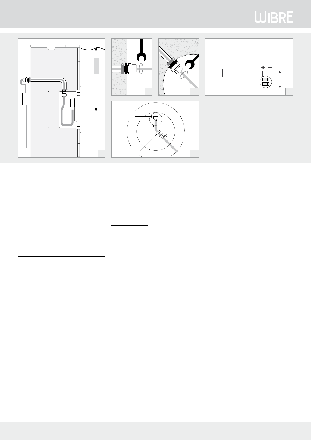
Bei nicht werksseitig angeschlossenem Kabel, das UW-Kabel durch
die innenliegende Kabelverschraubung des Einbaugehäuses in das
Kabelschutzrohr einführen und ca. 1,5 m Kabel im Einbaugehäuse
belassen. Die Kabelverschraubung festziehen, damit das Kabel abge-
dichtet wird. 3.10.
Am Scheinwerfer rückseitig die Anschlußeinheit öffnen, das Kabel
durch die Kabelverschraubung am Scheinwerfer einführen, ent-
sprechend an den Anschlussklemmen am Scheinwerfer anschließen
und die Kabelverschraubung verschließen. Danach den Deckel mit
O-Ring-Dichtung am Scheinwerfer mit 2,5 Nm verschrauben. 3.11.
Scheinwerfer wie oben beschrieben einbauen.
Verunreinigungen und Ablagerungen auf Glas oder Edelstahlteilen
sind mit handelsüblichen Reinigungsmitteln zu entfernen.
5. Allgemeine Wartungshinweise
• Beim Reinigen darf die Leuchte nicht mit Metall angreifenden Reini-
gungsmitteln in Berührung kommen. Der Einsatz salzsäurehaltiger
Reinigungsmittel an und in der Nähe von Scheinwerferteilen aus
Edelstahl ist in jedem Fall zu unterlassen.
• Scheinwerfer und Einbaugehäuse regelmäßig reinigen, um Fremd-
rostablagerungen zu vermeiden.
• Achtung: Keine Hochdruckreiniger verwenden.
• Strahler vor Einfrieren schützen, gegebenenfalls müssen diese
demontiert oder speziell geschützt werden.
•Verlorengegangene Schraubendürfennur durchSchraubenausV4A
ersetzt werden.
• Je nach Beanspruchung (Höhe derWatttage) undWasserqualität ist
alle 5–8 Jahre einWechsel der Dichtungen (Glasscheibe, Verschrau-
bung, O-Ring) und der Kabel zu empfehlen.
6. Garantiebestimmungen
Unsere Garantiebedingungen finden Sie auf der jeweiligen
Garantiekarte des Produkts und unter wibre.de/warranty.
7. Wichtige Hinweise
(Bei Nichtbeachtung folgender Punkte,
entfällt die Garantie.)
•Vor der Installation müssen alle Teile auf Transportschäden über-
prüft werden!
• Jegliche Montage-, Installations- und Elektroarbeiten müssen von
qualifiziertem Fachpersonal durchgeführt werden.
• Zur Vermeidung von Gefährdungen darf eine beschädigte äußere
flexible Leitung dieser Leuchte ausschließlich vom Hersteller, sei-
nem Servicevertreter oder einer vergleichbaren Fachkraft ausge-
tauscht werden.
• Die Lichtquelle dieser Leuchte darf nur vom Hersteller oder einem
von ihm beauftragten Servicetechniker oder einer vergleichbar qua-
lifizierten Person ersetzt werden.
• ZurVermeidung von Fremdrost nur Edelstahlwerkzeug verwenden!
• Die Kabellänge der Leuchten ist so zu wählen, dass man nicht im
Wasser oder feuchten Umgebung verlängern muss. Spätere Rekla-
mationen aufgrund dessen können nicht akzeptiert werden.
• Es dürfen nur originale Wibre-Betriebsgeräte verwendet werden.
• Ein Montageabstand von 10 cm zwischen Betriebsgeräten wird
dringend empfohlen, um wechselseitiges Erhitzen zu vermeiden.
• Anschluss der Betriebsgeräte muss stromlos erfolgen, da sonst
Entladungen im Netzteil zur Schädigung der LED führen können.
Es darf keine Primärspannung beim Wechsel der LED anliegen.
• Beim Anschließen der Leuchte die Polung beachten! Eine falsche
Polung kann dem LED-Modul schaden.
• Die Installation eines bauseitigen Überspannungsschutzes nach
DIN VDE 0100-443, DIN VDE 0100-534 und EN 62305 wird empfoh-
len.
• Bitte achten Sie auf Maßnahmen gegen ESD (Elektrostatische Entla-
dung) während aller Arbeiten am Scheinwerfer, Betriebsgerät und
LED.
4. Cable connection and maintenance
With non-factory connected cable, guide the UW cable cable through
the inside cable fitting of the installation housing into the cable
conduit and leave approx. 1.5 m of cable in the installation housing.
Tighten the cable fitting so that the cable is sealed. 3.10.
Open the connector on the rear of the spotlight, guide the cable
through the cable fitting on the spotlight, connect to the correspon-
ding terminals on the spotlight and close the cable fitting.Then screw
the cover with O-ring seal on to the spotlight to a torque of 2.5 Nm.
3.11.
Install the spotlight as described above.
Remove dirt and deposits on the glass or stainless steel parts with
commercially available cleaning agents.
5. General maintenance instructions
• During cleaning, the light may not come into contact with cleaning
agents that attack metals. The use of cleaning agents containing
hydrochloric acid on and close to the spotlight parts made from
stainless steel is to be avoided under all circumstances.
• Clean spotlight regularly, to avoid external rust deposits.
• Important: Do not use high-pressure cleaners.
• Protect spotlights from freezing; if appropriate, they may need to be
dismantled or specially protected.
• Lost screws or nuts may only be replaced by screws fromV4A.
• Depending on load (wattage) and water quality, we recommend
changing the seals (on the glass pane, fitting, O-ring) and cable
every 5–8 years.
6. Guarantee provisions
Our warranty conditions can be found on the respective warranty card
for the product and at wibre.de/warranty.
7. Important information
(If the following points are disregarded,
the guarantee expires.)
• Before installation, all parts must be checked for transport damage!
• All fitting, installation and electrical work must be performed by
qualified specialist staff.
•To avoid any hazards, a damaged external flexible cable of this lu-
minaire should only be replaced by the manufacturer, his service
representative or a comparable specialist.
•The light source of this luminaire may only be replaced by the ma-
nufacturer or a service technician appointed by him or a comparably
qualified person.
• Only use stainless steel tools to avoid external rust!
•The cable length of the lights should be chosen in such a way that
it is not necessary to extend in water or moist environments. Later
complaints resulting from this cannot be accepted.
• Only original Wibre operating units may be used.
• An installation distance of 10 cm between operating devices is ur-
gently recommended in order to avoid mutual heating up.
•The operating devices must be connected without power, as other-
wise discharges in the power supply may cause the LED to be dama-
ged. No primary voltage may be applied when changing the LED.
• Note polarity when changing the lights!The wrong polarity can da-
mage the LED module.
• It is recommended that the customer install an overvoltage protec-
tion in accordance with DIN VDE 0100-443, DIN VDE 0100-534 and
EN 62305.
• Please comply with all anti-ESD (electrostatic discharge) measures
during all work on the spotlight, operating device and LED.
Procéder au raccordement électrique des différents fils conducteurs
aux blocs d‘alimentation en respectant les prescriptions. 3.9.
Nombre maximal de lampes et type de raccordement, voir également
le manuel du bloc d‘alimentation ou contrôleur RVBB correspondant.
Remarque : Si le câble n‘est pas raccordé au départ usine, se re-
porter au point 4.
4. Raccordement de câble et maintenance
Si le câble n‘est pas raccordé au départ usine, introduire le câble suba-
quatique dans le raccord de câble intérieur du boîtier d‘encastrement
dans la gaine de protection des câbles et laisser env. 1,5 m de câble
dans le boîtier d‘encastrement. Serrer fermement le raccord de câble
pour que le câble soit étanchéifié. 3.10.
Ouvrir l‘unité de raccordement à l‘arrière du projecteur, introduire le
câble à travers le raccord de câble sur le projecteur, le raccorder de
manière adaptée aux bornes de raccordement du projecteur et fermer
le raccord de câble.Visser ensuite le couvercle avec le joint torique sur
le projecteur avec un couple de 2,5 Nm. 3.11. Installer le projecteur
comme indiqué ci-dessus. Éliminer les saletés et les dépôts sur le ver-
re ou les pièces en acier inoxydable avec un détergent courant.
5. Consignes de maintenance générales
• Lors du nettoyage, la lampe ne doit pas entrer en contact avec des
produits de nettoyage attaquant le métal. L‘utilisation de produits
de nettoyage contenant de l‘acide chlorhydrique sur des ou à proxi-
mité de pièces du projecteur en acier inoxydable est interdite dans
tous les cas.
• Nettoyer régulièrement les projecteurs afin d‘éviter des dépôts de
rouille extérieurs.
• Attention: n‘utiliser aucun appareil de nettoyage haute pression.
• Protéger les projecteurs du gel. Le cas échéant, ils doivent être dé-
montés ou être protégés de manière spécifique.
• Les vis ou écrous perdus doivent exclusivement être remplacés par
des vis enV4A.
• Selon la sollicitation (puissance) et la qualité de l‘eau, il est recom-
mandé de procéder au changement des joints (sur les vitres, les
raccords vissés et les joints toriques) et du câble tous les 5 à 8 ans.
6. Conditions de garantie
Nos conditions de garantie se trouvent sur la carte de garantie corre-
spondante du produit et sous wibre.de/warranty.
7. Remarques importantes (La garantie s‘éteint
en cas de non-respect des points suivants)
• L‘absenced‘avariesde transportdoit être vérifiéeavantl‘installation!
•Tous les travaux de montage et d‘installation, ainsi que les travaux
électriques, doivent être réalisés par du personnel qualifié.
• Pour éviter tout danger, un câble flexible externe endommagé du
projecteur ne peut être remplacé que par le fabricant, son représen-
tant de service ou un spécialiste qualifié.
• La source lumineuse de ce liminaire ne peut être remplacée que par
le fabricant ou un technicien de service désigné par lui ou par une
personne ayant une qualification comparable.
• Afin d‘éviter tout dépôt de rouille, utiliser exclusivement des outils
en acier inoxydable !
• La longueur de câble des lampes doit être choisie de telle sorte à ce
qu‘il ne soit pas nécessaire de la prolonger dans de l‘eau ou dans un
environnement humide. Toute réclamation ultérieure à ce motif ne
sera pas acceptée.
• Seuls des équipementsWibre originaux doivent être utilisés.
• Une distance de montage de 10 cm entre les équipements est vive-
ment recommandée afin d‘éviter un réchauffement mutuel.
• Le raccordement des équipements doit être effectué sans courant,
sans quoi des décharges dans le bloc d‘alimentation pourraient ent-
raîner une détérioration des LED. Aucune tension primaire ne doit
être établie lors du changement des LED.
• Lors du raccordement des lampes, respecter la polarité ! Une erreur
de polarité peut endommager le module de LED.
• L‘installation d‘une protection contre la surtension par le client
conforme aux normes DIN VDE 0100-443, DIN VDE 0100-534 et
EN 62305 est recommandée.
•Veuillez respecter les mesures contre la décharge électrostatique
durant tous les travaux sur des projecteurs, équipements et LED.
W974 Stand 08.20 - Technische Änderungen vorbehalten - Für Druckfehler übernehmen wir keine Haftung
Other Wibre Swimming Pool Lighting manuals
Popular Swimming Pool Lighting manuals by other brands

Bestway
Bestway 58111 operating instructions

Champlain
Champlain ACM-198 quick start guide

Pentair
Pentair AQUALUMIN III installation guide

Pentair
Pentair INTELLIBRITE 5G Installation and user guide

Vinyl Works
Vinyl Works ORGPP2 Safety & installation instructions

OR STEEL light
OR STEEL light DRAGONNET 12-24VDC Technical manual