manuals.online logo
Brands
  1. Home
  2. •
  3. Brands
  4. •
  5. System Sensor
  6. •
  7. Marine Equipment
  8. •
  9. System Sensor LASS-WSS-NC User manual

System Sensor LASS-WSS-NC User manual

1 I56-5925-000
INSTALLATION AND MAINTENANCE INSTRUCTIONS
Model LASS-WSS-NC
Addressable Wall Mount Sounder&Strobe
Xi'an System Sensor Electronics Ltd.
28 Tuanjie South Road
Xi'an Hi-tech Development Zone
710075, China
Tel: (+86) 029 85387800 Fax: (+86) 029 88332959
SPECIFICATION
Item Parameter Description Note
Operating Voltage DC24V( DC15V~ DC32V)
Avg. Standby Current <400µA 24VDC, No Communication, No sounding/flashing
Alarm Current <11mA High Volume, 24VDC
<8.5mA Low Volume, 24VDC
Operating Temp -25℃~+70℃
Humidity 10~95% R.H. Non-condensing
Ingress Protection IP33
IP35(With Water-proof box )
High Volume
90±4dB(A) 1m , High Volume, Tone 21 @24V
92±3dB(A) 1m , High Volume, Tone 13 @24V
91±5dB(A) 1m , High Volume, Tone 12 @24V
95±5dB(A) 1m , High Volume, Tone 19 @24V
Low Volume
86±3dB(A) 1m , Low Volume, Tone 21 @24V
86±4dB(A) 1m , Low Volume, Tone 13 @24V
81±3dB(A) 1m , Low Volume, Tone 12 @24V
84±6dB(A) 1m , Low Volume, Tone 19 @24V
Tone Type 4 See table 1: ‘Sound setting ’ for detailed tones
Flash Pattern 2 See table 2: ‘Flash Pattern’
Flash Intensity >1cd
Coverage Volume W-3-6/O-3-6
Height 47mm
Diameter 122mm
Weight 176±6g
Meet the following Standards requirements:
EN54-3 & EN54-23
AS ISO 7240.3:2014 & AS ISO 7240.23:2014
Before installing and using the product, please read the system
wiring and installation manual thoroughly. If the products will
be installed in an existing operational system, inform the operator
and local authority that the system will be temporarily out of
service, disconnect power to the control panel before installing the
products.
NOTICE: This manual should be left with the owner/user of this
equipment.
GENERAL
LASS-WSS-NC is an intelligent addressable AV products
designed to alarm light/sound for emergency events, and be
able to communicate with control panel by intelligent protocol.
It is designed specifically for analogue addressable fire alarm
system and only can be connected to control panels with a
compatible proprietary analogue addressable communication
protocol. It is powered from the loop and can be controlled via
the communication protocol(s). The Wall Mount Version is
compatible with B501 mounting base. Up to 99 addresses are
available via two rotary selector switches. The sounders have
2 volume levels (high/low) and 4 tone sets. The alarm
light/sound can be tested on field.
INSTALLATION
It must be installed and wired with B501 mounting base.
1. Verify the product type matches with product drawing.
2. Set the address via two rotary selector switches. Please
refer to “Address setting”.
3. Volume and tone setting are realized by 4 digit DIP witch.
On field testing can be tested via DIP switch.
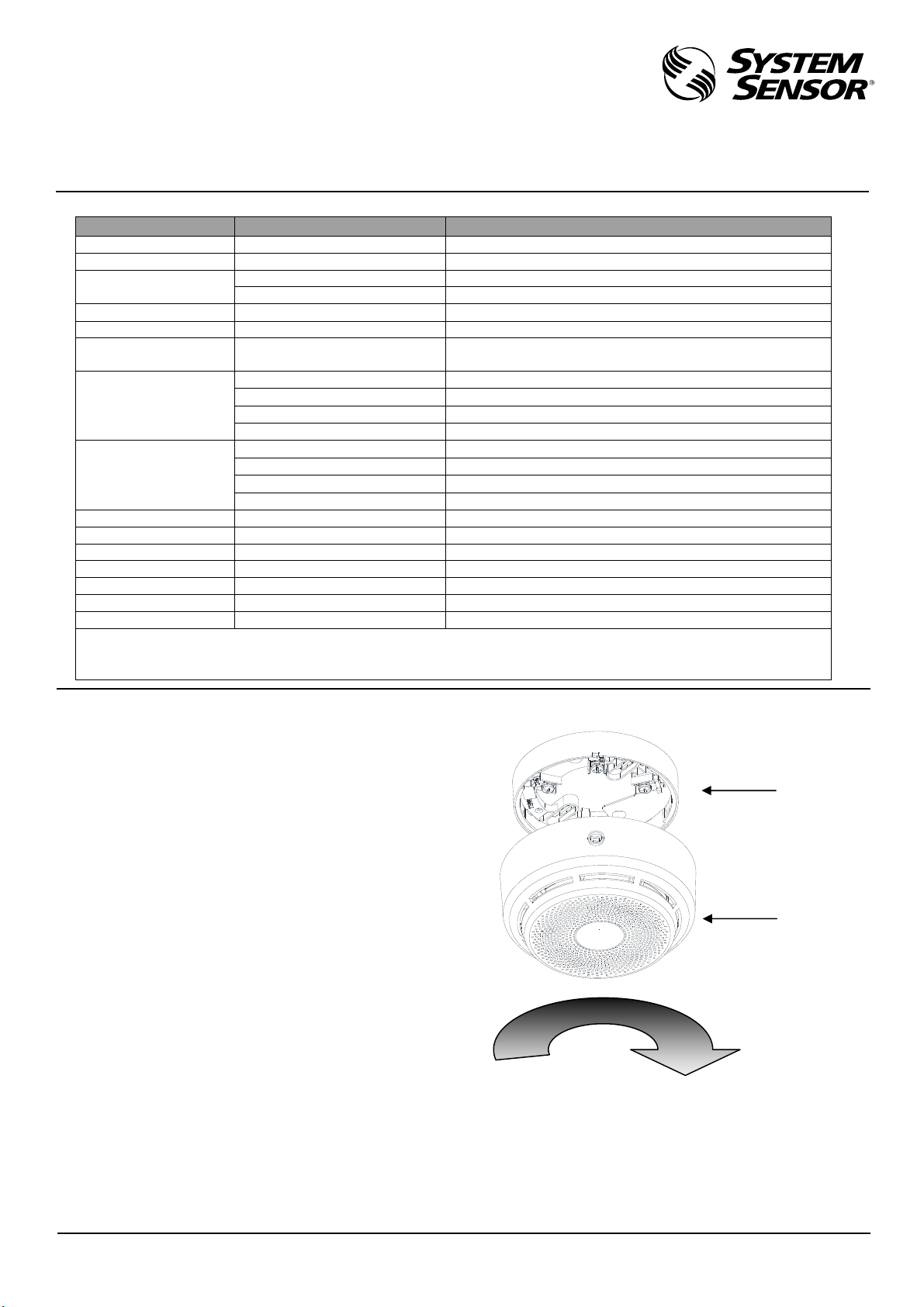
4. Plug the Wall Mount Sounder& Strobe into B501 mounting
base.
5. Turn the Wall Mount Sounder& Strobe clockwise until it
drops into place.
6. Continue turning the Wall Mount Sounder& Strobe clockwise
to lock it in place.
Figure 1
SETTING
Address setting
Rotary-decade switches are provided for setting the address
whose range is from 1 to 99. (Default address is 01).
Address is set by turning the switches.
Address is calculated as below formula: Address = TENS *10
+ ONES*1. For instance: Address 05 = 0*10 + 5*1.
I56-5925-000
A5665‐006
B501
Mounting
Base
Wall Mount
Sounder&
Strobe
2 I56-5925-000
Figure 2
Tamper-resistant capability
Addressable Wall Mount Sounder& Strobe include a tamper-
resistant capability that prevents its removal from the B501
base and the removal of installed detector without the use of a
tool.
When B501 mounting base enables tamper-resistant function,
special tools must be used to disassemble addressable base.
Please refer to below figure: use straight screwdriver to break
specific position, then insert the screwdriver and maintain in
its position. Then you can disassemble the Wall Mount Sounder&
Strobe by turning anticlockwise
Figure 3
Table 1: Sound setting
Bit:1, 2, 3, 4
(0 = off/1 =
on/X=random)
Description
Tone
setting
0 0 X X
Tone 21(second stage: tone 12)
400HZ
1200HZ
1 Sec 4 Sec
0 1 X X
Tone 13(second stage: tone 12)
500HZ
1200HZ
0.25 Sec 3.75 Sec
1 0 X X
Tone 12(second stage: tone 13)
Off
420HZ
0.625 Sec 0.625 Sec
1 1 X X
Tone 19(second stage: tone 12)
4 Sec
1 Sec
Off
950HZ
Volume
setting
X X 1 X High volume
X X 0 X Low volume
Test setting
please set
to 0 under
normal use
X X X 1 Field testing on
X X X 0 Field testing off
Table 2: Flash Pattern
Flash Pattern Description
Evacuate flash pattern
Synchronized with Tone
21, 19 or 13
Alert flash pattern
Synchronized with Tone 12
Synchronization
When the Wall Mount Sounder& Strobe send out a fire alarm,
control panel can send out a certain signal to synchronize all
the addressable AV in same loop to send out fire alarm signal.
Note: Please dispose electronic waste following national or local
regulations after being scrappedor replaced. Do not discard.
Figure 4 System wiring diagram
THREE-YEAR LIMITED WARRANTY
Xi’an System Sensor warrants its enclosed product to be free from
defects in materials and workmanship under normal use and service
for a period of three years from date of manufacture. Xi’an System
Sensor makes no other express warranty for the enclosed product. No
agent, representative, dealer, or employee of the Company has the
authority to increase or alter the obligations or limitations of this
Warranty. The Company’s obligation of this Warranty shall be limited
to the replacement of any part of the product which is found to be
defective in materials or workmanship under normal use and service
during the three year period commencing with the date of
manufacture. After phoning Xi’an System Sensor for a Return
Authorization Number and faxing a copy of the filled CUSTOMER
RETURNS with authorized RA# to Xi’an System Sensor, send Defective
units with a copy of the form posta
g
e prepaid to: Xi’an System Sensor
Electronics, Ltd./ 28 Tuan Jie South Road/ Xi’an National Hi-tech
Industrial Development Zone, 710075/ China. Please include a note
describing the malfunction and suspected cause of failure. The Company
shall not be obligated to replace units which are found to be defective
because of damage, unreasonable use, modifications, or alterations
occurring after the date of manufacture. In no case shall the Company
be liable for any consequential or incidental damages for breach of this
or any other Warranty, expressed or implied whatsoever, even if the
loss or damage is caused by the Company’s negligence or fault. Some
states do not allow the exclusion or limitation of incidental or
consequential damages, so the above limitation or exclusion may not
apply to you. This Warranty gives you specific legal rights, and you
may also have other rights which vary from state to state.
Ver. A
A5665‐007
A5665‐005
1 Sec 4 Sec
1.25 Sec
A5665‐002
ONES
DIP switch
for tone
setting
COMM+
COMM-
TENS

Other System Sensor Marine Equipment manuals

System Sensor B200S-LF User manual

System Sensor

System Sensor B200S-LF User manual

System Sensor B401BH-2 User manual

System Sensor

System Sensor B401BH-2 User manual

System Sensor EBS User manual

System Sensor

System Sensor EBS User manual

System Sensor B200S User manual

System Sensor

System Sensor B200S User manual

System Sensor B501BHT-2 User manual

System Sensor

System Sensor B501BHT-2 User manual

System Sensor ExitPoint PF24 User manual

System Sensor

System Sensor ExitPoint PF24 User manual

System Sensor B200S-LF-WH User manual

System Sensor

System Sensor B200S-LF-WH User manual

System Sensor B501BH-2 User manual

System Sensor

System Sensor B501BH-2 User manual

System Sensor B200S User guide

System Sensor

System Sensor B200S User guide

System Sensor L Series Technical specifications

System Sensor

System Sensor L Series Technical specifications

System Sensor B501BHT-2 User manual

System Sensor

System Sensor B501BHT-2 User manual

System Sensor MASS12LO User manual

System Sensor

System Sensor MASS12LO User manual

System Sensor ExitPoint PF24V User manual

System Sensor

System Sensor ExitPoint PF24V User manual

System Sensor SpectrAlert Advance User manual

System Sensor

System Sensor SpectrAlert Advance User manual

Popular Marine Equipment manuals by other brands

Torqeedo Travel 503 operating manual

Torqeedo

Torqeedo Travel 503 operating manual

TracPhone V7 Replacement instructions

TracPhone

TracPhone V7 Replacement instructions

Raymarine M81130 installation guide

Raymarine

Raymarine M81130 installation guide

ShipModul MiniPlex-2Wi manual

ShipModul

ShipModul MiniPlex-2Wi manual

Furuno FE-800 Operator's manual

Furuno

Furuno FE-800 Operator's manual

Furuno IF-7000 Operator's manual

Furuno

Furuno IF-7000 Operator's manual

ADVANSEA Speed s400 user manual

ADVANSEA

ADVANSEA Speed s400 user manual

Furuno CSH-5 MARK-2 Operator's guide

Furuno

Furuno CSH-5 MARK-2 Operator's guide

Mercury Joystick Piloting for Outboards manual

Mercury

Mercury Joystick Piloting for Outboards manual

Lowrance ActiveTarget 2 installation manual

Lowrance

Lowrance ActiveTarget 2 installation manual

Simrad AP20 manual

Simrad

Simrad AP20 manual

Furuno FI-302 Operator's manual

Furuno

Furuno FI-302 Operator's manual

TradeQuip PORTA POWER KIT owner's manual

TradeQuip

TradeQuip PORTA POWER KIT owner's manual

Humminbird 700 series Installation & operation manual

Humminbird

Humminbird 700 series Installation & operation manual

Blink Marine PKP-1400 user manual

Blink Marine

Blink Marine PKP-1400 user manual

DMT Alpha Series user manual

DMT

DMT Alpha Series user manual

Kenwood KMR-700U - Radio / Digital Player instruction manual

Kenwood

Kenwood KMR-700U - Radio / Digital Player instruction manual

Kongsberg EA 600 instruction manual

Kongsberg

Kongsberg EA 600 instruction manual

manuals.online logo
manuals.online logoBrands
  • About & Mission
  • Contact us
  • Privacy Policy
  • Terms and Conditions

Copyright 2025 Manuals.Online. All Rights Reserved.