Copy Part# 682147, Rev. C Page 5 of 8
Date: 02/2017
© 2015 Marine Canada Acquisition Inc. DBA SEASTAR SOLUTIONS 3831 No. 6 Road, Richmond, B.C. Canada V6V 1P6 Fax: 604.270.7172 Web: www.seastarsolutions.com
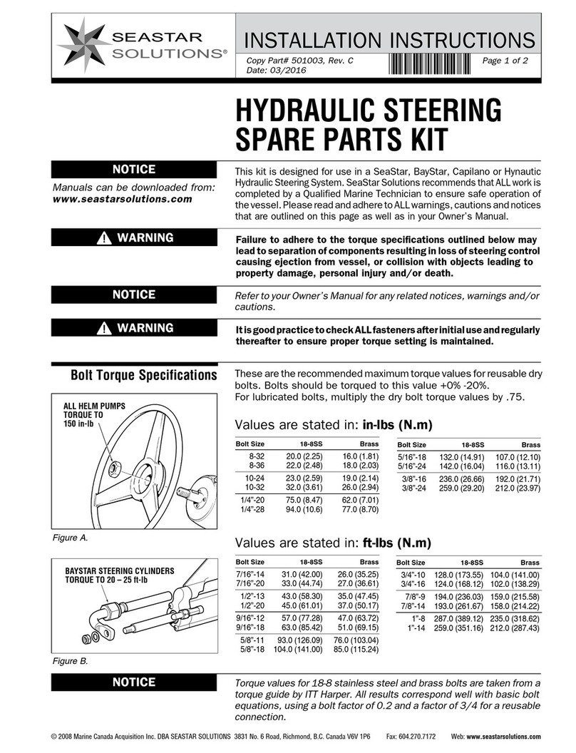
SUPPLEMENT INSTRUCTIONS
Crimp instructions:
• Strip the wires 1/4” to 3/8” (6 to 10 mm) from the end.
• With the wire ends properly seated in the splice, crimp using
the recommended tool.
• Apply heat directly to the splice with a hot air gun or other heat
source. Work from the center out to the edges until the outer
sleeve shrinks, the crimp marks disappear, and the adhesive
melts onto the wire.
• Allow the splice to cool, then check the integrity of the splice.
For systems using Optimus EPS outboard steering cylinders, a basic
system setup, purge, and calibration can be performed with the
dash panel. Refer to the procedure below.
For all other steering cylinders, you will need to connect a CANtrak
Display setup tool (ED1700) and follow the setup procedure in
Book 65.
Procedure:
1. Turn the ignition on while pressing and holding the pushbutton
on the dash panel. Hold the button down for 3 seconds after
the ignition is switched on.
2. Release the button for 3 seconds, then press it again for at
another 3 seconds. (If you steer the helm during this setup
entry procedure you will need to start over.)
3. The dash panel lamp will flash red and the buzzer will beep
once to indicate that the system is in setup mode. The
system will automatically be configured as a single engine
system with no CANtrak display. Auto-detect parameters (see
below) are set to default values.
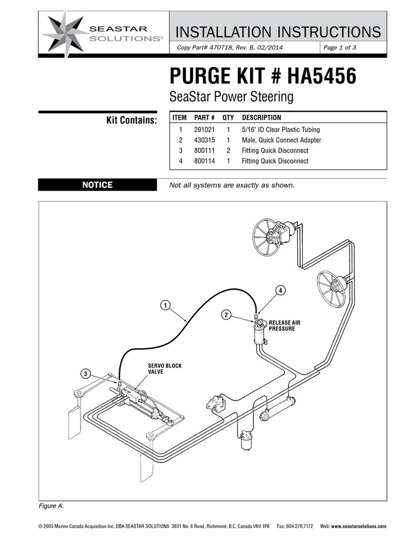
4. Purge the system. See instructions on the next page.
5. After the purge is completed, calibrate the system as follows:
steer in one direction until you hear a brief beep from the buzzer,
indicating that you’ve reached a hard stop. Steer in the other
direction until you hear the beep indicating the second hard
stop. The system should now be calibrated.
6. Complete the setup by cycling the system power. When you turn
on the system it should be fully operational with a steady blue
indicator light. If the red light is flashing attempt to calibrate
again by following steps 1–5 (you should not need to purge again).
If the fault persists connect to the system with a CANtrak or
Datalink to diagnose the problem.
Auto-Detect Parameters
Auto-detect parameters are changed automatically, but in one
direction only. To return to the default value you will need to
repeat the setup.
Setup, Purge and Calibration
NOTICE
All installation steps must be
completed before proceeding.
NOTICE
If the buzzer sounds continuously
during calibration it means that the
hoses are installed to the wrong
ports. Swap them at the pump and
start the setup over again.
PARAMETER DEFAULT AUTO-DETECT BEHAVIOR
Engine RPM
Source
Analog
tachometer
If a valid RPM message is seen on the NMEA2000 network, the
RPM Source will switch to NMEA2000. If NMEA2000 is then
disconnected the system will fault.
Number of
Helms
1 If two helms are detected on CAN1 the number of helms will
change to 2. If a helm is then disconnected the system will fault.
