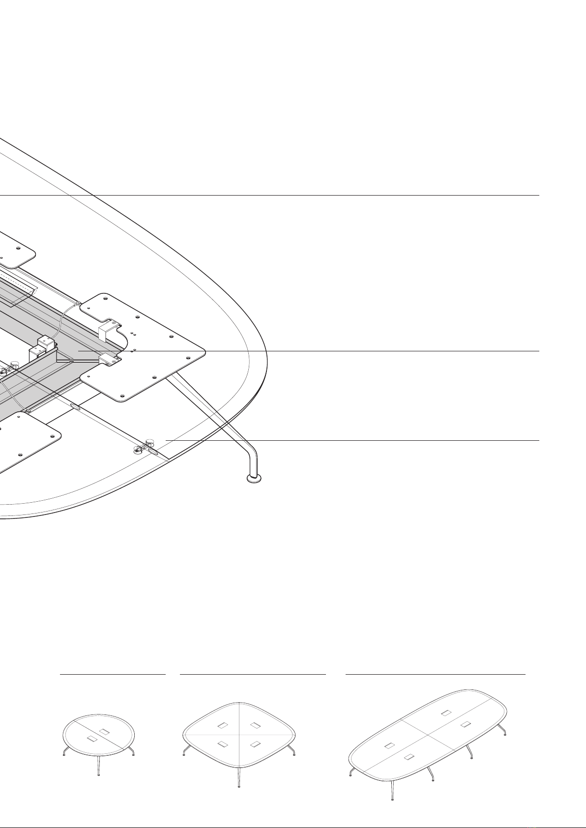
Wilkhahn Graph 300 range User manual
Other Wilkhahn Indoor Furnishing manuals

Wilkhahn
Wilkhahn AT Series User manual

Wilkhahn
Wilkhahn Neos Series User manual

Wilkhahn
Wilkhahn Aline Series User manual

Wilkhahn
Wilkhahn Graph 300 Series User manual

Wilkhahn
Wilkhahn Logon User manual

Wilkhahn
Wilkhahn ON Series User manual

Wilkhahn
Wilkhahn Timetable Lift User manual

Wilkhahn
Wilkhahn Decide User manual

Wilkhahn
Wilkhahn ON. User manual
Popular Indoor Furnishing manuals by other brands

Regency
Regency LWMS3015 Assembly instructions

Furniture of America
Furniture of America CM7751C Assembly instructions

Safavieh Furniture
Safavieh Furniture Estella CNS5731 manual

PLACES OF STYLE
PLACES OF STYLE Ovalfuss Assembly instruction

Trasman
Trasman 1138 Bo1 Assembly manual

Costway
Costway JV10856 manual