Winmate FA33 User manual

FA33
MAINBOARD
MANUAL
DOC No.: M01204
Rev. :A0
Date : 3, 2001
Part No. : 25-11434-20

Handling Precautions
Warning:
1. Static electricity may cause damage to the integrated circuits on
the motherboard. Before handling any motherboard outside of its
protective packaging, ensure that there is no static electric charge
in your body.
2. There is a danger of explosion if the battery is incorrectly
replaced. Replace only with the same or an equivalent type
recommended by the manufacturer.
3. Discard used batteries according to the manufacturer’s
instructions.
4. Never run the processor without the heatsink properly and firmly
attached. PERMANENT DAMAGE WILL RESULT!
Observe the following basic precautions when handling the motherboard
or other computer components:
nWear a static wrist strap which fits around your wrist and is
connected to a natural earth ground.
nTouch a grounded or anti-static surface or a metal fixture such as a
water pipe.
nAvoid contacting the components on add-on cards, motherboards,
and modules with the golden fingers connectors plugged into the
expansion slot. It is best to handle system components by their
monting brackets.
The above methods prevent static build-up and cause it to be discharged
properly.
Trademark
All trademarks mentioned in this manual are registered properly of
the respective owners.
Handling Precautions
This manual may not, in whole or in part, be photocopied, reproduced,
transcribed, translated, or transmitted in whatever form without the
written consent of the manufacturer, except for copies retained by the
purchaser for personal archival purposes.
Notice

i
Tableof Contents
Table of Contents
Chapter 1 Overview
Package Checklist .......................................................................... 1-2
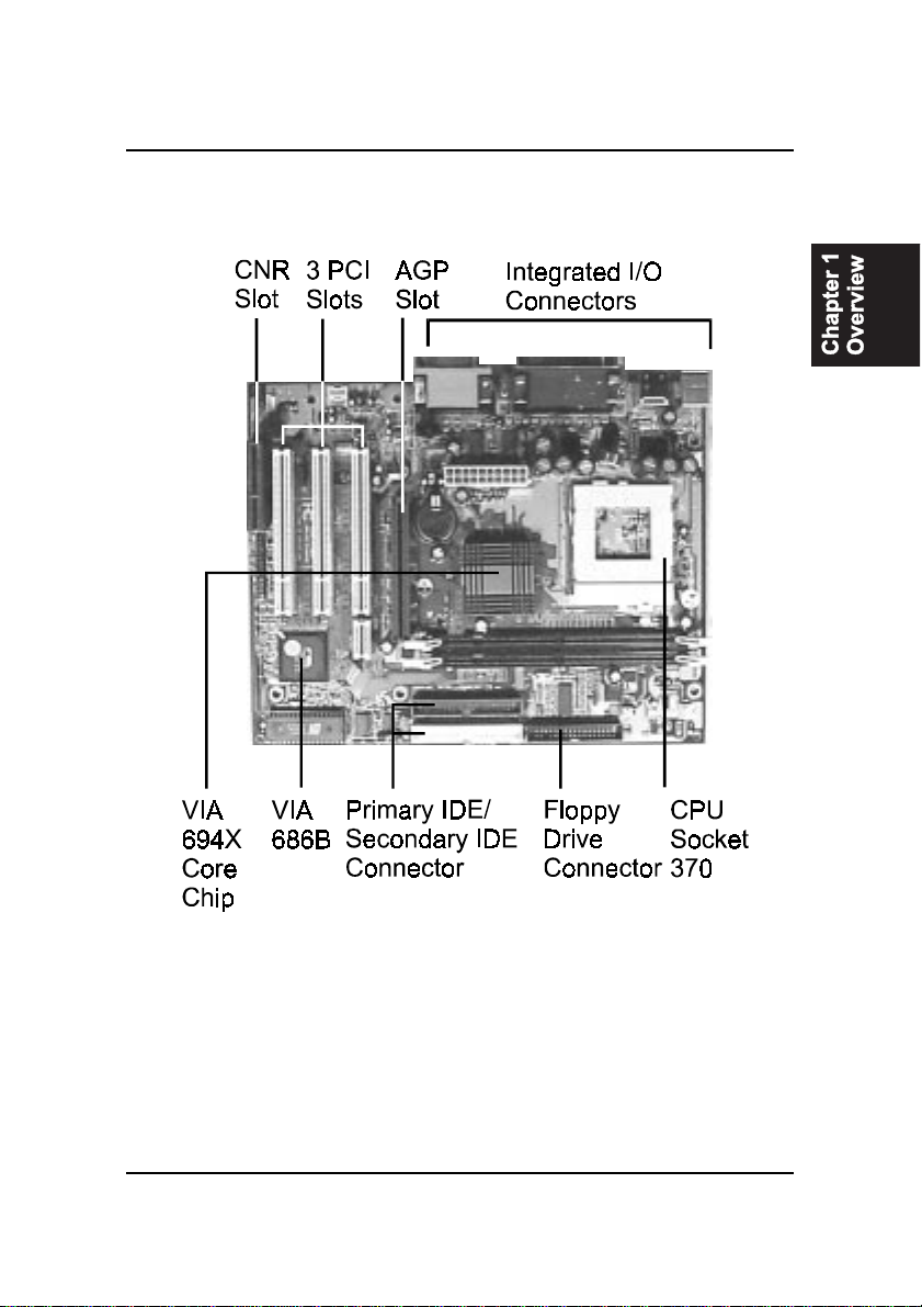
The FA33 Mainboard ..................................................................... 1-3
Main Features ................................................................................ 1-4
ACPI Ready ................................................................................... 1-6
Chapter 2 Installation Procedures
Quick Reference (from Page 2-2 to 2-4) .......................................... 2-2
Mainboard Layout .................................................................... 2-2
1). Clear CMOS, CPU/Bus Ratio Select, FSB Speed Select 2-3
2). Front Panel Block Cable Connection ............................ 2-4
3). CPU Fan Installation .................................................... 2-4
1). Set System Jumpers .................................................................. 2-5
Clear CMOS Data: JP1 ....................................................... 2-6
CPU/Bus Ratio Select: JP2 ................................................. 2-6
FSB Speed Select: JP3, JP4 ................................................ 2-7
2). Install Memory Modules .......................................................... 2-8
Install and Remove DIMMs .............................................. 2-8
3). Install the CPU .......................................................................... 2-9
4). Install Expansion Cards ............................................................. 2-10
5). Connect Devices ....................................................................... 2-11
Floppy Diskette Drive Connector ..................................... 2-11
IDE Device Connectors ..................................................... 2-12
ATX Power Connector ...................................................... 2-12
CPU Fan Connector .......................................................... 2-13
System Case Fan Connector ............................................. 2-13
Wake-On-LAN Connector ................................................. 2-14
Infrared Connector ............................................................ 2-14
CD Audio-In Connector (CN2) .......................................... 2-14
Auxiliary Audio-In Connector (CN3) ................................ 2-15
Audio Mono In/Out Connector (CN4) .............................. 2-15
Front Panel Block Connector ............................................ 2-16
PS/2 Keyboard and Mouse Connector ............................. 2-17
Universal Serial Bus Connectors ....................................... 2-17
Printer Connector .............................................................. 2-18
Serial Port Connectors ....................................................... 2-18
GAME/MIDI Connector .................................................... 2-19

ii
FA33Mainboard Manual
Audio I/O Jacks ................................................................ 2-19
Chapter 3 BIOS Setup
CMOS Setup Utility ....................................................................... 3-1
Standard CMOS Setup ................................................................... 3-2
Hard Disk Configurations .......................................................... 3-2
Advanced BIOS Features .............................................................. 3-3
Advanced Chipset Features .......................................................... 3-6
Integrated Peripherals .................................................................... 3-9
Power Management Setup ............................................................. 3-14
PNP/PCI Configurations ................................................................ 3-18
PC Health Status ............................................................................ 3-20
Frequency/Voltage Control ............................................................ 3-21
Load Fail-Safe Defaults .................................................................. 3-22
Load Optimized Defaults ................................................................ 3-22
Supervisor/User Password ............................................................ 3-23
Save and Exit Setup ....................................................................... 3-24
Exit without Saving ........................................................................ 3-24
Quick Reference (German) G-1
Quick Reference (French) F-1
Quick Reference (Spanish) S-1
Quick Reference (Japanese) J-1
Quick Reference (Chinese) C-1
Quick Reference (Simplified Chinese) |||||||||||||SC-1

1 - 1
Overview
Overview
Chapter 1
The new Micro ATX, Socket 370 1stMainboard FA33 supports a full range of
the latest generation Intel® processors. Intels new Celeron and lightening
fast Coppermine processors of up to 1GHz*, are supported with Front Side
Bus of 66 / 100 / 133 MHz.
The FA33 is based around the VIA Apollo Pro 694X North-Bridge and the VIA
Super South. The North Bridge supports AGP 4X bandwidth which enables
the increase of the AGP bus of up to 66x4 MHz, providing vastly improved
data transfer speeds for graphics as well as reducing power consumption. The
VIA Super South supports Sound Blaster Pro, which provides exceptional
onboard audio capabilities.
With 2 DIMM, the FA33 affords a large 1.0 GB of memory support, while
support for the PC133 protocol results in a highly promoted and advanced
system performance. Ultra DMA 66/100 allows for high-range bandwidth and
high-speed data transfer necessary for the improvement of idle CPU sequen-
tial transfers.
Extensive connectivity is provided by 2 serial ports, 1 parallel port, 1 PS/2
mouse and 1 keyboard connector, 4 USB connectors(2 in rear side, 2 in front
side) and 1 media connector ( MIDI/Game port, Line-in, Line-out, Mic-in). 1
AGP 4x, 1 CNR and 3 PCI provide additional expansion.

1 - 2
FA33Mainboard Manual
Package Checklist
If you discover any item below was damaged or lost, please contact your
vendor.
þThe mainboard þThis user manual
þOneFDD cable þOne HDD cable
þOne ATA/66 cable þOne Software CD (CD Pro)

1 - 3
Overview
The FA33 Mainboard

1 - 4
FA33Mainboard Manual
Main Features
■Easy Installation
||BIOS with support for Plug and Play, auto detection of IDE hard drives,
||LS-120|drives, IDE ZIP drives, Windows 95/98SE, Windows ME, Win-
dows 2000, |Windows NT|4.0, and OS/2.
■Leading Edge Chipset
VIA Apollo Pro 694X and 686B (with Sound Blaster Pro compatible
embeded in) provide integrated DRAM controllers with new Dynamic
Power Management Architecture (DPMA), concurrent PCI (2.0/2.1), AGP
1.0/2.0 compliant and USB.
■Versatile Main Memory Support
Accepts up to 1.0 GB DRAM using two DIMMs of 16, 32, 64, 128, 256,
512MB with support for lightning-fast SDRAM (66/100/133MHz).
■■
■■
■Super Multi Input/Output (I/O) Support
Integrated Plug and Play multi-I/O chipset features one high-speed UART
16550 compatible serial ports, one infrared port, one EPP/ECP capable
parallel port, and one FDD connector.
■Flexible Processor Support
Onboard CPU socket supports:
Intel® Celeron PPGA/FC-PGA 433/500/533/566/600/633/667/700/733/766
MHz and up at 66 MHz FSB
Intel® CuMine FC-PGA 500/550/600/650/700/750/800/850 MHz and up
at 100MHz FSB
Intel® CuMine FC-PGA 533/600/667/733/800/866/933 MHz/1GHz at
133MHz FSB

1 - 5
Overview
■■
■■
■Convenient Rear Panel USB Connection Support
Two USB ports integrated in the rear I/O panel with one manufacturing
optional USB connector for two front panel USB connections allow con-
venient and high-speed Plug and Play connections to the growing num-
ber of USB compliant peripheral devices on the market.
■■
■■
■Remote Wake On LAN Support
Onboard Wake On LAN (WOL) connector allows remote management on
your network even the system is power off. The feature provides a sim-
pler and convenient control to LAN-based networks.
■AGP, CNR, and PCI Expansion Slots
One AGP Bus expansion slot, three PCI Bus expansion slots, and one
CNR Bus slot provide the room to install a full range of add-on cards.
■■
■■
■Onboard Accelerated Graphics Port (AGP)
The motherboard is installed one 32-bit AGP bus with a dedicated 66MHz/
133MHz path from the graphics card to the system memory (in 4x mode)
offering much greater bandwidth than the 32-bit PCI bus does. AGP en-
abled 3D graphics cards can directly access main memory across this fast
path instead of using local memory. To make use of the improved AGP
performance, the motherboard should be installed with SDRAM type
memory and the VGA card and drivers should also be fully AGP compli-
ant. Using Microsofts Windows 98 and Windows 2000 which implement
DirectDraw will allow the system to take full use of AGPs benefits with-
out the need to install additional drivers.
■Enhanced PCI Bus Master IDE Controller with Ultra DMA 33/66/100
Support
Integrated Enhanced PCI Bus Master IDE controller features two dual-
channel connectors that up to four Enhanced IDE devices, including CD-
ROM and Tape Backup Drives, as well as Hard Disk Drives supporting
the new Ultra DMA 100 protocol. Standard PIO Mode 3, PIO Mode 4,
DMA Mode 2, DMA Mode 4, UltraDMA-100 Mode 5 devices are also
supported.

1 - 6
FA33Mainboard Manual
ACPI Ready
This mainboard fully implements the new ACPI (Advanced Configuration and
Power Interface) 1.0B Hardware and BIOS requirement. If you install ACPI
aware of operating system, such as Windows 98, you fully utilized the power
saving under ACPI. (Windows ME/2000 Professional supports ACPI func-
tions.)

2 - 1
Installation Procedures
Chapter 2
Installation Procedures
The mainboard has several user-adjustable jumpers on the board that allow you to
configure your system to suit your requirements. This chapter contains information
on the various jumper settings on your mainboard.
To set up your computer, you must complete the following steps:
■ Step 1 - Set system jumpers/switches
■ Step 2 - Install memory modules
■ Step 3 - Install the Central Processing Unit (CPU)
■ Step 4 - Install expansion cards
■ Step 5 - Connect ribbon cables, cabinet wires, and power supply
■ Step 6 - Set up BIOS software
■ Step 7 - Install supporting software tools
WARNING: Excessive torque may damage the mainboard. When
using an electric screwdriver on the mainboard, make sure that
the torque is set to the allowable range of 5.0 ~ 8.0kg/cm.
Mainboard components contain very delicate Integrated Circuit
(IC) chips. To prevent static electricity from harming any of the
mainboard’s sensitive components, you should follow the
following precautions whenever working on the computer:
1. Unplug the computer when working on the inside.
2. Hold components by the edges and try not to touch the IC
||||chips, leads, or circuitry.
3. Wear an anti-static wrist strap which fits around the wrist.
4. Place components on a grounded anti-static pad or on the bag
that came with the component whenever the components are
separated from the system.

2 - 2
FA33Mainboard Manual
Mainboard Layout
Quick Reference (from Page 2-2 to 2-4)

2 - 3
Installation Procedures
1). Clear CMOS, CPU/Bus Ratio Select,
FSB Speed Select

2 - 4
FA33Mainboard Manual
3). CPU Fan Installation
This connector is linked to the CPU fan. When the system is in suspend mode, the
CPU fan will turn off; when it reverts back to full on mode, the fan will turn back on.
Without sufficient air circulation, the CPU may overheat resulting in damage
to both the CPU and the mainboard.
Damage may occur to the mainboard and/or the CPU fan if these pins are
used incorrectly. These are not jumpers, do not place jumper caps over these
pins.
2). Front Panel Block Cable Connection

2 - 5
Installation Procedures
1). Set System Jumpers
Jumpers are used to select the operation modes for your system. Some jump-
ers on the board have three metal pins with each pin representing a different
function. A 1 is written besides pin 1 on jumpers with three pins. To set a
jumper, a black cap containing metal contacts is placed over the jumper pin/s
according to the required configuration. A jumper is said to be shorted when
the black cap has been placed on one or two of its pins. The types of jumpers
used in this manual are shown below:
NOTE: Users are not encouraged to change the jumper settings
not listed in this manual. Changing the jumper settings improperly
may adversely affect system performance.

2 - 6
FA33Mainboard Manual
Clear CMOS Data: JP1
To clear the contents of the CMOS, please follows the steps below:
(1). Turn off the power supply of the computer system. (2). Place the jumper
cap on the pin pair 2-3 for 5 seconds, then put the cap back to the pin pair 1-2.
(3). Turn on the power of the system. (4). Enter BIOS CMOS Setup Utility and
Select Load Setup Defaults. Type Y and press Enter key. (5). Set the system
configuration in the Standard CMOS Setup menu.
CPU/Bus Ratio Select: JP2
This feature allows users to select a CPU at a higher frequency clock ratio than
that specification allows. It may or may not run at this ratio, depending on the
quality of the processor and the extent to which the ratio has been overset;
howerever, this option will not work with those frequency-locked CPUs.

2 - 7
Installation Procedures
FSB Speed Select: JP3, JP4
This feature allows users to select the front side bus speed. Set both jumper
caps to pin pair 1-2 (Auto is the default setting) if you are not sure what front
side bus frequency that your processor support.

2 - 8
FA33Mainboard Manual
Press the clips with both hands to remove the DIMM.
2). Install Memory Modules
This mainboard provides two onboard DIMM sockets supporting 3.3V (un-
buffered) SDRAM DIMM modules. Either 32, 64, 128, 256, 512 MB DIMM can
be installed on these three sockets. The maximum total memory supported is
up to 1.0 GB.
Install and Remove DIMMs
1. Locate the DIMM slots on the mainboard.
2. Install the DIMM straight down into the DIMM slot using both hands.
3. The clip on both ends of the DIMM slot will close up to hold the DIMM
in place when the DIMM reaches the slots bottom.

2 - 9
Installation Procedures
To install the CPU, do the following:
1. Lift the lever on the side of the CPU socket.
2. Handle the chip by its edges and try not to touch any of the pins.
3. Place the CPU in the socket. The chip has two notches to correctly locate
the chip. Align two notches of the processor with the two triangular
marks on the socket. Do not force the chip. The CPU should slide easily
into the socket.
4. Swing the lever to the down position to lock the CPU in place.
5. Place the cooling fan with heatsink on top of the installed CPU.
3). Install the CPU
The mainboard has built-in Switching Voltage Regulator to support CPU Vcore
autodetection. That is, It has the ability to detect and recognize the CPU
voltage, clock, ratio and enables users to set up the CPU frequency from the
BIOS Setup Screen. Users can adjust the frequency through Frequency /
Voltage Control of the BIOS Setup Screen.

2 - 10
FA33Mainboard Manual
4). Install Expansion Cards
This section describes how to connect an expansion card to one of your
systems expansion slots. Expansion cards are printed circuit boards that,
when connected to the mainboard, increase the capabilities of your system.
For example, expansion cards can provide video and sound capabilities. The
mainboard features three PCI bus, one CNR bus and one AGP bus expansion
slots.
CAUTION: Make sure to unplug the power supply when adding or
removing expansion cards or other system components. Failure to
do so may cause severe damage to both the mainboard and
expansioncards.
Always observe static electricity precautions.
Please read “Handling Precautions” at the start of this manual.
To install an expansion card, follow the steps below:
1. Remove the computer chassis cover and select an empty expansion
slot.
2. Remove the corresponding slot cover from the computer chassis.
Unscrew the mounting screw that secures the slot cover and pull
the slot cover out from the computer chassis. Keep the slot cover
mounting screw nearby.
Other manuals for FA33
2
Table of contents
Other Winmate Motherboard manuals

Winmate
Winmate I370 User manual

Winmate
Winmate IA70 User manual

Winmate
Winmate IK70 User manual

Winmate
Winmate FA33 User manual

Winmate
Winmate IH32 User manual

Winmate
Winmate IH32 User manual

Winmate
Winmate IK70 User manual

Winmate
Winmate IB32 User manual

Winmate
Winmate IP70 User manual

Winmate
Winmate IT70 User manual

Winmate
Winmate V270 User manual

Winmate
Winmate IV32 User manual

Winmate
Winmate IQ30-100 User manual

Winmate
Winmate IB70 User manual

Winmate
Winmate A830 SBC User manual

Winmate
Winmate IA30 User manual

Winmate
Winmate IB32 User manual

Winmate
Winmate ID31 User manual

Winmate
Winmate IH70 User manual

Winmate
Winmate IV70 User manual