WiT VL53-400 User manual

VL53-400 | Manual v23-0215 | www.wit-motion.com
- 2 -
Tutorial Link
Google Drive
Link to instructions DEMO:
WITMOTION Youtube Channel
If you have technical problems or cannot find the information that you need in the
provided documents, please contact our support team. Our engineering team is
committed to providing the required support necessary to ensure that you are
successful with the operation of our AHRS sensors.
Contact
Technical Support Contact Info
Application
●Robot
●UAV
●Intelligent Device

VL53-400 | Manual v23-0215 | www.wit-motion.com
- 3 -
Contents
Tutorial Link .................................................................................... - 2 -
Contact...........................................................................................- 2 -
Application ......................................................................................- 2 -
Contents......................................................................................... - 3 -
1 Overview......................................................................................- 4 -
2 Size.............................................................................................- 5 -
3 Parameter .................................................................................... - 6 -
4 Pin ..............................................................................................- 7 -
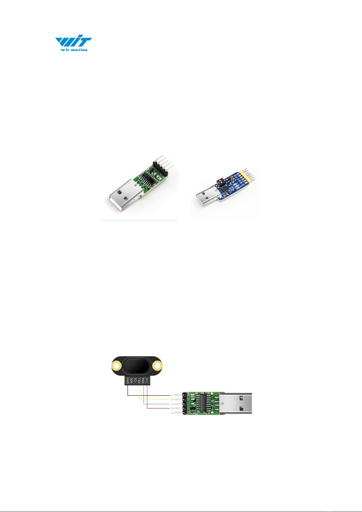
5 Hardware Connection .....................................................................- 9 -
5.1 PC Connection ......................................................................- 9 -
5.2 IIC Connection.................................................................... - 10 -
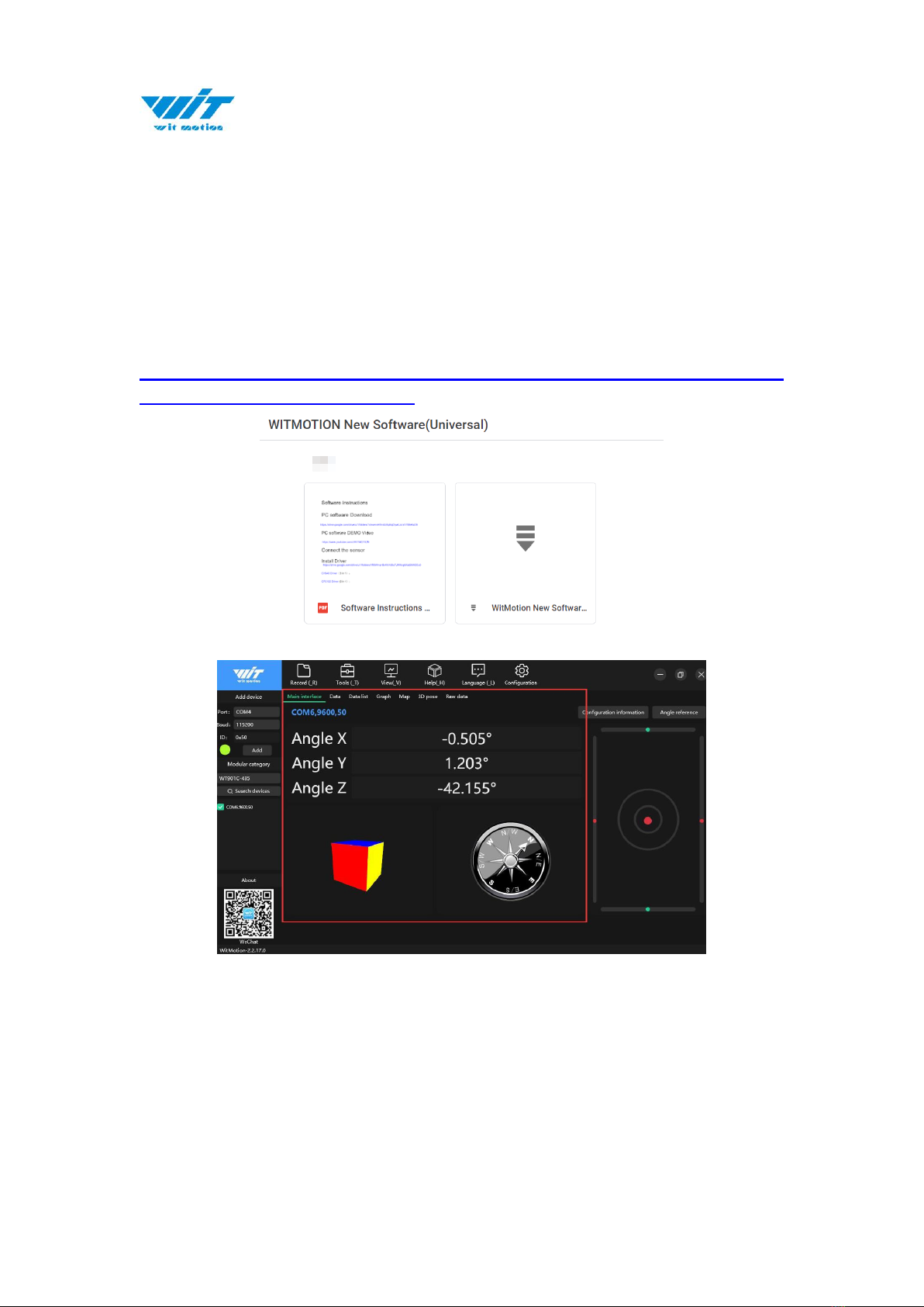
6 Software Connection .................................................................... - 12 -
6.1 Device ............................................................................... - 12 -
6.2 Data View .......................................................................... - 13 -
6.3 ID ..................................................................................... - 14 -
6.4 Reset................................................................................. - 15 -
6.5 Baud Rate .......................................................................... - 16 -
6.6 Return Rate........................................................................ - 17 -
6.7 Calibration Module............................................................... - 18 -
6.8 Measurement Mode ............................................................. - 19 -
7 Communication Protocol ............................................................... - 21 -
7.1 Serial Mode ........................................................................ - 21 -
7.2 Modbus Protocol.................................................................. - 22 -
7.3 Modbus Register ................................................................. - 24 -
7.4 IIC Mode............................................................................ - 27 -

VL53-400 | Manual v23-0215 | www.wit-motion.com
- 4 -
1 Overview
With voltage stabilization circuit, working voltage 3.3V~5V, compatible
with 3.3V embedded system.
Supports serial, Modbus, and IIC modes.
Two kinds of digital interface serial port and IIC, IIC is directly
connected to the chip.
Data output rate up to 100Hz. 0.1~100Hz (default 100Hz) can be
adjusted.
2-layer PCB board process, thinner, smaller and more reliable. Metal
shielding cover to prevent static interference.
Default short-distance mode (the longest measurement distance is 2
meters), when measuring 4 meters, change to the long-distance mode.

VL53-400 | Manual v23-0215 | www.wit-motion.com
- 6 -
3 Parameter
Parameter
Specification
Voltage
3.3V-5V
Current
<33mA
Size
20mm x13mm x6.2mm
0.787" x 0.511" x0.244"
Fixed Hole
Spacing 16mm, hole radius 1mm
Spacing 0.630", hole radius 0.039"
Return Rate
0.1~100HZ(default 10Hz)
Measuring Distance
40mm-4000mm (4000mm without optical cover)
1.575"-157.480" (157.480"without optical cover)
Interface
Level TTL
Baud Rate
Supports 2400-921600, default 115200
Ranging Error
±20mm (±0.787")

VL53-400 | Manual v23-0215 | www.wit-motion.com
- 7 -
4 Pin
Pin Explanation
Number
Pin
Explanation
1
VCC
3.3V-5.0V power output
2
RXD
Serial port receiving pin
(TTL level, not directly connected to RS232 level)
can be connected to the TXD of the microcontroller
3
TXD
Serial port sending pin
(TT level, not directly connected to RS232 level)
can be connected to the RXD of the microcontroller
4
SCL
IIC communication clock pin
(need to enter IIC mode)
5
SDA
IIC communication data pin
(need to enter IIC mode)
6
GND
Ground

VL53-400 | Manual v23-0215 | www.wit-motion.com
- 8 -
5 Instructions of 2023 New Software
In order to improve the user experience and our customer service, we develop
a new version PC software.
Below is the new software and universal instruction download link.
https://drive.google.com/drive/folders/1dnwmnH7mi4zBpNqDywLzr
zsV7BfeKaD9?usp=share_link
Note:
The 2022 old version software will be reserved for use. You can check
“Chapter 3 Use Instructions with PC”for more details. ↓↓↓

VL53-400 | Manual v23-0215 | www.wit-motion.com
- 9 -
6 Hardware Connection
6.1 PC Connection
To connect with a computer, a serial port module with USB to TTL level is
required. We recommend the following two USB to serial modules:
3-in-1 serial converter 6-in-1 serial converter
Step 1. Connect the sensor with a serial converter
PIN Connection:
VCC -5V
TX - RX
RX - TX
GND –GND
Step 2. Plug it into computer.
PC-serial module connection diagram:

VL53-400 | Manual v23-0215 | www.wit-motion.com
- 10 -
6.2 IIC Connection
6.3 Serial Connection
Step 1. Connect the sensor with offered Type-C wire.
(Warm Reminder:If you wanna use a longer cable,it should be a standard
Type-C data cable)
Step 2. Unzip the software and install the driver CH340
https://drive.google.com/file/d/1I3hl9Thsj9aXfG6U-cQLpV9hC3bVEH2V/view?
usp=sharing
*How to Install and update the CH340 driver
Click the "Uninstall" button first. Then click on the "Install" button.

VL53-400 | Manual v23-0215 | www.wit-motion.com
- 11 -
*How to verify your driver is working
1)To check that the CH340 enumerates to a COM port, you can open the device
manager. You can click the Start or ⊞(Windows) button and type "device
manager to quickly search for the application.
2)After opening the device manager, you will need to open the Ports (COM &
LPT) tree. The CH340 should show up as USB-SERIAL CH340 (COM##).
Depending on your computer, the COM port may show up as a different number.

VL53-400 | Manual v23-0215 | www.wit-motion.com
- 12 -
7 Software Connection
Notice:
1. The sensor and the measured object should be as parallel as possible. If there
is a deviation, the angle cannot be greater than the laser emission angle.
2. To detect fast-moving objects, the sampling frequency should be adjusted
(VL53-400 sets the timing preset time and measurement time interval).
3. The laser light source is an invisible beam to the naked eye (the laser can be
seen with a mobile phone camera). Obstacles in the emission angle of the light
source will affect the ranging effect.
4. The module is affected by natural light. In general, the stronger the natural
light, the greater the impact. That is, the ranging distance becomes shorter, the
accuracy becomes worse, and the fluctuation becomes larger. Under strong light
(such as sunlight), it is generally recommended to be used in close-range
detection scenarios.
7.1 Device
Step 1. Connect the module to the computer through the serial port module.
Step 2. Query the corresponding serial port number in the device manager, as
follows:

VL53-400 | Manual v23-0215 | www.wit-motion.com
- 14 -
7.3 ID
When there are multiple Modbus connections, need to set different Modbus IDs
read data normally. After setting the ID, the data can be read normally only
when the computer is used to search for the device again. The device ID is saved
after power off.
Step 1. Click "Configuration" to select the corresponding device and enter the
configuration interface.
Step 2. Entering “Device ID” click "Set up". ID can be set in the range
0x00~0x7F.

VL53-400 | Manual v23-0215 | www.wit-motion.com
- 15 -
7.4 Reset
Reset will restore all user setting parameters to the default state.
Step 1. After connecting the sensor normally, click "Configuration" to enter the
configuration interface.
Step 2. Click “Reset”, If the baud rate or ID is not the default setting (default
baud rate: 115200, ID: 0X50), search for the device again.

VL53-400 | Manual v23-0215 | www.wit-motion.com
- 16 -
7.5 Baud Rate
After the normal connection, the baud rate can be modified on the computer.
Step 1. Click "Configuration" to select the corresponding device and enter the
configuration interface.
Step 2. Click “Communication rate”, select the baud rate.

VL53-400 | Manual v23-0215 | www.wit-motion.com
- 17 -
7.6 Return Rate
The sensor can set the automatic return speed of 0.1~100Hz (due to the
influence of the measurement distance, the time is not absolutely accurate, and
the return rate is useless in Modbus mode.)
Step 1. After connecting the sensor normally, click "Configuration" to select the
corresponding device and enter the configuration interface.
Step 2. Click “Return rate”.

VL53-400 | Manual v23-0215 | www.wit-motion.com
- 18 -
7.7 Calibration Module
The sensor can be calibrated manually, fix the sensor, place a white object at a
distance of 14cm (5.512") in front of the sensor and click to calibrate.
Step 1. After connecting the sensor normally, click "Configuration" to select the
corresponding device and enter the configuration interface.
Step 2. Fix the sensor and calibration object, click "Calibration module".

VL53-400 | Manual v23-0215 | www.wit-motion.com
- 19 -
7.8 Measurement Mode
The laser ranging module can set three distance modes, the short-distance
mode has a maximum measurement distance of 1.3 meters, the
medium-distance mode has a maximum measurement distance of 3 meters,
and the long-distance mode has a maximum measurement distance of 4 meters.
The default setting is long-distance mode.
Step 1. After connecting the sensor normally, click "Configure" to select the
corresponding device and enter the configuration interface.
Step 2. Click “Measurement mode”.

VL53-400 | Manual v23-0215 | www.wit-motion.com
- 20 -
Notice:
When changing the measurement mode, the computer automatically changes
the setting values of the two registers, 0x07 (timing preset time) and 0x08
(measurement interval) according to the mode selection.
The setting values of the computer are as follows:
Example of serial:
MODADDR 06 00 07 00 14 CRCH CRCL // Set 7 register is 20
Time delay100ms
MODADDR 06 00 08 00 01 CRCH CRCL // Set 8 register is 1
Time delay100ms
MODADDR 06 00 36 00 01 CRCH CRCL // Set to short-distance
Measurement Mode
Timing Preset Time
(0x07)
Measurement Interval
(0x08)
Default
20
1
Short-distance
20
1
Medium-distance
250
50
Long-distance
250
50
Table of contents
Other WiT Accessories manuals
Popular Accessories manuals by other brands

Goobay
Goobay 58690 user manual

Honeywell Home
Honeywell Home C7189U installation instructions

Keystone
Keystone WT09 quick start guide

M-Edge
M-Edge Guardian case Instructions and warranties

Leuze electronic
Leuze electronic IPS 258i Original operating instructions

Britax
Britax BOB Gear Travel Bag Instruction