WiT WT901BLECL 5.0 User manual

https://wiki.wit-motion.com/english
WhatsApp:+86 13652339539 E-mail:support@wit-motion.com Web:https://wiki.wit-motion.com/english
- 1 -
WT901BLECL Bluetooth 5.0 Gyro Sensor
SPECIFICATION
Model :WT901BLECL 5.0
Description :Bluetooth 5.0 AHRS IMU sensor with battery
Quality system standard: ISO9001:2016
Tilt switch production standard:GB/T191SJ 20873-2016
Criterion of detection:GB/T191SJ 20873-2016
Revision date:2019.12.16
Link to WT901BLECL BLE 5.0 tutorial:(software, manual, etc.):
https://drive.google.com/open?id=1TWqkdsXo-yMxBGp3Px6CokytSHNwPS1R
Link to demo video of WT901BLECL BLE 5.0:
https://www.dropbox.com/sh/n5ujs8vswagvqve/AADPVFA_1FA7gAr4aW6T8yMxa?dl=0

https://wiki.wit-motion.com/english
WhatsApp:+86 13652339539 E-mail:support@wit-motion.com Web:https://wiki.wit-motion.com/english
- 2 -
Catalog
1 Description...................................................................................................- 3 -
2 Product Size.................................................................................................- 3 -
3 Features........................................................................................................- 4 -
4 Axial Diron.................................................................................................. - 4 -
5 Method.........................................................................................................- 5 -
5.1 Connect App......................................................................................- 5 -
5.2 Clibration method..............................................................................- 8 -
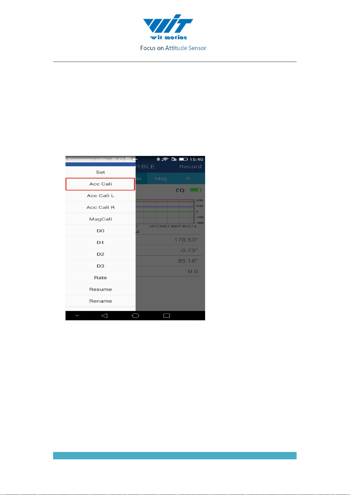
5.2.1 Acceleration calibration............................................................ - 9 -
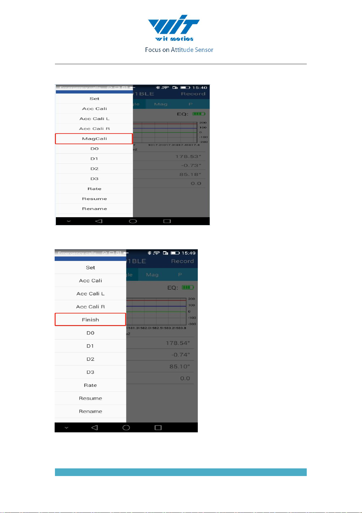
5.2.2 Magnetic Calibration.................................................................- 9 -
5.3 Connect to PC software...................................................................- 11 -
5.3.1 Calibration by Instruction........................................................- 15 -
5.4 Restore Factory Setting................................................................... - 15 -
5.5 Sleep/ Wake up................................................................................- 15 -
6 Communication Protocol...........................................................................- 15 -
6.1 Module to APP................................................................................ - 16 -
6.1.1 Acceleration, Angular velocity, Angle, Data pack(default).... - 16 -
6.1.2 Single Return Register Data Packet........................................ - 17 -
6.2 APP to Module................................................................................ - 19 -
6.2.1 Read register value.................................................................. - 19 -
6.2.2 Accelerometer Calibration and Magnetic Calibration............ - 20 -
6.2.3 Save Settings........................................................................... - 20 -
6.2.4 Set Return Rate........................................................................- 20 -
Set Port D0..........................................................................................- 20 -
Set Port D1..........................................................................................- 21 -
Set Port D2..........................................................................................- 21 -
Set Port D3..........................................................................................- 21 -

https://wiki.wit-motion.com/english
WhatsApp:+86 13652339539 E-mail:support@wit-motion.com Web:https://wiki.wit-motion.com/english
- 3 -
6.3 Register address.............................................................................. - 21 -
7. Application Area..........................................................................................- 24 -
1 Description
Module integrates high-precision gyroscope, accelerometer, mpu9250 geomagnetic sensor,
high-performance microprocessors and advanced dynamics solves dynamic Kalman filter
algorithm to quickly solve the current real-time movement of the module attitude .
The use of advanced digital filtering technology, can effectively reduce the measurement
noise and improve measurement accuracy.
Integrates gesture solver, with dynamic Kalman filter algorithm, can get the accurate attitude
in dynamic environment, attitude measurement precision is up to 0.05 degrees with high
stability, performance is even better than some professional Inclinometer!
Integrate voltage stabilization circuit, working voltage is 3.3v ~ 5v, pin level compatible
3.3V and 5V embedded system .
High-performance cortex-M0 core processor runs at up to 50MHz, taking into account low
power consumption and high performance.
BLE 5.0 wireless transmission, transmission stability, distance greater than 50 meters.
Low power consumption, long standby time, self-contained battery.
Stamp hole gold plating process can be embedded in the user's PCB board.
4-layer PCB technology, thinner, smaller, and more reliable.
2 Product Size

https://wiki.wit-motion.com/english
WhatsApp:+86 13652339539 E-mail:support@wit-motion.com Web:https://wiki.wit-motion.com/english
- 4 -
3 Features
1、Voltage:3.3V~5V
2、Working current: ≈15mA, broadcast current: ≈150uA, standby current: 10uA~50uA
3、Volume:51.3 X 36 X 15mm
4、Measuring dimensions:
Acceleration: X Y Z
Angular velocity: X Y Z
Attitude angle:X Y Z
Magnetic field:XYZ
6、Range: Acceleration: ± 16g, Angular velocity: ± 2000 ° / s,Angle:X Z ±180° Y ±90°
7、Stability: Acceleration: 0.01g, Angular speed 0.05° / s.
8、Attitude measurement stable:X Y 0.05° Z :1°
9、Data output: Acceleration, Angular velocity, Angle,Magnetic field, Port status
10、The data output frequency: 0.1Hz ~50Hz (10Hz default)
11、Data Interface: UART(TTL , Baud rate 115200)
12、Expansion port function:Analog input(0~VCC, Digital input, Digital output)
13、Bluetooth transmission distance:>50m
14、BLE 5.0:Support Android /IOS
4 Axial Diron
As shown in the figure above, the coordinates of the module are indicated, and the upper is
the X-axis, the left is Y axis, the Z axis is perpendicular to the surface of the paper to yourself.

https://wiki.wit-motion.com/english
WhatsApp:+86 13652339539 E-mail:support@wit-motion.com Web:https://wiki.wit-motion.com/english
- 5 -
The direction of rotation is defined by the right hand rule. that is, the thumb of the right hand is
pointed to the axial direction, and the four is the direction of the bending of the right hand.
5 Method
5.1 Connect App
Android App
1. The module builds with a battery,open switch on the side, and open the APP search
directly. If you can't find the module, the battery may be out of power. Plug in the data cable
and try again.
2. Open the mobile app and click “Scan” to start searching for Bluetooth. The Bluetooth
name is “WT901BLE50”.

https://wiki.wit-motion.com/english
WhatsApp:+86 13652339539 E-mail:support@wit-motion.com Web:https://wiki.wit-motion.com/english
- 6 -
3. Click on the Bluetooth name, the APP cuts into the data display window, and you can see
the data returned by the module.

https://wiki.wit-motion.com/english
WhatsApp:+86 13652339539 E-mail:support@wit-motion.com Web:https://wiki.wit-motion.com/english
- 7 -
5.1.1 iOS app
Link to app: https://cw.pub/vrn5
Step 1: Open link by safari and download the app

https://wiki.wit-motion.com/english
WhatsApp:+86 13652339539 E-mail:support@wit-motion.com Web:https://wiki.wit-motion.com/english
- 8 -
Step 2: Find device management and trust the app launcher.
The connection with IOS app has been shown as below:
5.2 Clibration method
The module needs to be calibrated before it can be used. Calibration of the module includes
additional calibration, magnetic field calibration.

https://wiki.wit-motion.com/english
WhatsApp:+86 13652339539 E-mail:support@wit-motion.com Web:https://wiki.wit-motion.com/english
- 9 -
5.2.1 Acceleration calibration
The addition calibration is used to remove the zero offset of the accelerometer. The sensor
will have different degrees of zero offset error at the factory, and the measurement will be
accurate after manual calibration.
1. To add calibration, the method is as follows: Firstly, keep the module horizontally
stationary, click to add calibration, after 1~2 seconds, the three axial values of the module
acceleration will be around 0 0 1 and the X and Y axis angles will be around 0°. After
calibration, the X Y-axis angle is accurate.
5.2.2 Magnetic Calibration
Magnetic field calibration is used to remove the magnetic field sensor's zero offset. Usually,
the magnetic field sensor will have a large zero error when it is manufactured. If it is not
calibrated, it will bring about a large measurement error and affect the accuracy of the Z-axis
angle measurement of the heading angle.
Calibration methods as follow:
1. When calibrating, first connect the module and the computer, and place the module in a
place far away from the disturbing magnetic field (ie, more than 20 CM away from magnets and
iron, etc.), and then open the upper computer software.
2. Click the “Magnetic Field Calibration”and rotate 360°around the X axis of the module
( you can rotate around the Y axis or the Z axis first). Rotate a few turns, then turn 360°around

https://wiki.wit-motion.com/english
WhatsApp:+86 13652339539 E-mail:support@wit-motion.com Web:https://wiki.wit-motion.com/english
- 10 -
the Y axis. Then turn 360°around the Z axis, then turn a few turns at random, then click the
“Finish” to complete the calibration.
1. Click the “Save” button to save the zero offset data to the internal FLASH of the module.
Thereafter, the module is able to output an accurate heading angle.
Note: The data displayed on the APP will not change when the calibration is completed.

https://wiki.wit-motion.com/english
WhatsApp:+86 13652339539 E-mail:support@wit-motion.com Web:https://wiki.wit-motion.com/english
- 11 -
After the calibration is completed, the data will continue to be transmitted back. When the
calibration is added, the module should be stationary. When the magnetic field is calibrated and
used, it must be kept away from the magnetic field interference.
5.3 Connect to PC software
if you want to connect this product to software, you should use the special
thread which put with product together, use it to connect to the software, we need device
CH340 and CP2012 driver to get it.
Driver installation:
First, install the driver CH340 when we used the USB serial module ,after
installed the driver. then get the corresponding Com number in the device
manager. Driver as followed:
https://wiki.wit-motion.com/english/doku.php?id=communication_module
Secondly, install the driver CP2102X when we used the USB serial
module ,after installed the driver. then get the corresponding Com number in the
device manager. Driver as followed:
https://wiki.wit-motion.com/english/doku.php?id=communication_module
After installing the module driver, and then Device Manager can query
corresponding serial number, as below figure shows:

https://wiki.wit-motion.com/english
WhatsApp:+86 13652339539 E-mail:support@wit-motion.com Web:https://wiki.wit-motion.com/english
- 12 -
You should use a usb cable to connect to PC software

https://wiki.wit-motion.com/english
WhatsApp:+86 13652339539 E-mail:support@wit-motion.com Web:https://wiki.wit-motion.com/english
- 13 -
Then Open the software “MiniIMU.exe” and select the Com number
which you have got in the device manager before.

https://wiki.wit-motion.com/english
WhatsApp:+86 13652339539 E-mail:support@wit-motion.com Web:https://wiki.wit-motion.com/english
- 14 -
Then the software will show the data

https://wiki.wit-motion.com/english
WhatsApp:+86 13652339539 E-mail:support@wit-motion.com Web:https://wiki.wit-motion.com/english
- 15 -
5.3.1 Calibration by Instruction
1.Instruct Accelerometer Calibration:
First keep the module horizontal and still, send the instruction: FF AA 01 01 00,
after 1~2s the acceleration X Y Z value will at 0 0 1. X Y angle: 0°. After calibration the value
will be accurate.
2. Accelerometer Calibration L/R:
Keep the module is still at left, send the instruction L: FF AA 01 05 00
After 2s, turn the module to the right side and send the instruction R: FF AA 01 06
00
Calibrate two times the data will be accurate.
3. Instruct Magnetic Calibration:
When calibrating, place the module in a place far away from the disturbing magnetic field
(ie, more than 20 CM away from magnets and iron, etc.). Send the instruction: FF AA 01 07
00
Rotate 360° around the X axis of the module ( you can rotate around the Y axis or the Z axis
first). Rotate a few turns, then turn 360° around the Y axis. Then turn 360° around the Z axis, then
turn a few turns at random, then click the “Finish” to complete the calibration.
Send the instruction: FF AA 01 00 00 to finish the calibration.
Send the instruction: FF AA 00 00 00 to save the Configuration.
5.4 Restore Factory Setting
Method: After connecting the WT901BLECL and APP via Bluetooth, click the
“Resume” .Reconnect the module after recovery.
5.5 Sleep/ Wake up
Enter the sleep mode right two methods. One is to disconnect the Bluetooth connection directly,
and the module will go directly to sleep mode. The other is to send a serial port command, the
instruction content is 5 hexadecimal data: 0xff 0xaa 0x67 0x01 0x00
There are two ways to wake up the module. One is to directly search for and connect to
Bluetooth. The module will wake up automatically and start working. The other is wake-up from
the serial port. Any serial port command can be sent to wake up the module.
6 Communication Protocol

https://wiki.wit-motion.com/english
WhatsApp:+86 13652339539 E-mail:support@wit-motion.com Web:https://wiki.wit-motion.com/english
- 16 -
6.1 Module to APP
Module upload Flag=0x61 (Angle,Angular velocity, Acceleration) data default.
Flag=0x71(Magnetic field, Air pressure and altitude, Port status) need to send the
corresponding register instruction.
Bluetooth upload data: Bluetooth uploads up to 20 bytes per data.
6.1.1 Acceleration, Angular velocity, Angle, Data pack(default)
Packet
header
1Byte
Flag bit
1Byte
axL
axH
…….
YawL
YawH
0x55
Flag
0xNN
0xNN
…….
0xNN
0xNN
Note: 0xNN is a accurate value you received. Data return sequence: Acceleration X Y Z
Angular velocity X Y Z Angle X Y Z , low byte first, high byte last.
Flag = 0x61 Data content: 18Byte is Acceleration, Angular velocity, Angle.
0x55
Packet header
0x61
Flag bit
axL
X Acceleration low 8 byte
axH
X Acceleration high 8 byte
ayL
Y Acceleration low 8 byte
ayH
Y Acceleration high 8 byte
azL
Z Acceleration low 8 byte
azH
Z Acceleration high 8 byte
wxL
X Angular velocity low 8 byte
wxH
X Angular velocity high 8 byte
wyL
Y Angular velocity low 8 byte
wyH
Y Angular velocity high 8 byte
wzL
Z Angular velocity low 8 byte
wzH
Z Angular velocity high 8 byte
RollL
X Angle low 8 byte
RollH
X Angle high 8 byte
PitchL
Y Angle low 8 byte
PitchH
Y Angle high 8 byte
YawL
Z Angle low 8 byte
YawH
Z Angle high 8 byte

https://wiki.wit-motion.com/english
WhatsApp:+86 13652339539 E-mail:support@wit-motion.com Web:https://wiki.wit-motion.com/english
- 17 -
Acceleration calculation method: Unit: g
ax=((axH<<8)|axL)/32768*16g(g is Gravity acceleration, 9.8m/s2)
ay=((ayH<<8)|ayL)/32768*16g(g is Gravity acceleration, 9.8m/s2)
az=((azH<<8)|azL)/32768*16g(g is Gravity acceleration, 9.8m/s2)
Calculation method: Unit: °/s
wx=((wxH<<8)|wxL)/32768*2000(°/s)
wy=((wyH<<8)|wyL)/32768*2000(°/s)
wz=((wzH<<8)|wzL)/32768*2000(°/s)
Calculation method: Unit: °
Roll(x axis)Roll=((RollH<<8)|RollL)/32768*180(°)
Pitch(y axis)Pitch=((PitchH<<8)|PitchL)/32768*180(°)
Yaw angle(z axis)Yaw=((YawH<<8)|YawL)/32768*180(°)
Note:
1. Attitude angle use the coordinate system for the Northeast sky coordinate system, the X
axis is East,the Y axis is North, Z axis toward sky. Euler coordinate system rotation
sequence defined attitude is z-y-x, first rotates around the Z axis. Then, around the Y
axis, and then around the X axis.
2. In fact, the rotation sequence is Z-Y-X, the range of pitch angle (Y axis) is only ±90
degrees, when the pitch angle (Y axis) is bigger than 90 degrees and the pitch angle (Y
axis) will become less than 90 degrees. At the same time, the Roll Angle(X axis) will
become larger than 180 degree. Please search on Google about more information of
Euler angle and attitude information.
3. Since the three axis are coupled, the angle will be independent only when the angle is
small. It will be dependent of the three angle when the angle is large when the attitude
angle change, such as when the X axis close to 90 degrees, even if the attitude angle
around the X axis, Y axis angle will have a big change, which is the inherent
characteristics of the Euler angle.
Explanation:
1. The data is sent in hexadecimal format, not ASCII code.
2. Each data is transmitted in descending order of high byte and high byte, and the two are
combined into one signed short type of data.
X axis acceleration data Ax: AxL is low byte, AxH is high byte, conversion method as
below:
Presume Data is a real data, DataH is high byte, DataL is low byte, so:
Data=((short)DataH<<8)|DataL. Please note that DataH need to transform a signed short type of
data and then shift. The Data type has a signed short type, so that it display negative number.
6.1.2 Single Return Register Data Packet
Single Return Data Packet need to send register instruction first:

https://wiki.wit-motion.com/english
WhatsApp:+86 13652339539 E-mail:support@wit-motion.com Web:https://wiki.wit-motion.com/english
- 18 -
FF AA 27 XX 00
--XX is register number. The register number please refer to 7.3. Example as below:
Function
Instruction
Read magnetic field
FF AA 27 3A 00
Read port status
FF AA 27 41 00
Read quaternion
FF AA 27 51 00
Read temperature
FF AA 27 40 00
After send instruction, the module turn back a data packet 0x55 0x71. There are register
address and 7 registers data (Fixed upload 8 registers). Return data format as below:
Start register(2 byte) + register data(16 byte, 8 registers)
Note: 0xNN is a accurate value, low byte first, high byte last.
1. Magnetic field output
0x71
0x3A
0x00
HxL
HxH
HyL
HyH
HzL
HzH
..
....
Calculated formular:Unit: mG
Magnetic field(x axis)Hx=(( HxH<<8)| HxL)
Magnetic field(y axis)Hy=(( HyH <<8)| HyL)
Magnetic field(z axis)Hz =(( HzH<<8)| HzL)
EX: Send instruction to read magnetic field in APP: FF AA 27 3A 00 (Please refer
to 7.2.8) The module return data to APP: 55 71 3A 00 68 01 69 00 7A 00 00 00 00 00 00 00 00
00 00 00 Total: 20 bytes.
Calculate the no.5 to no.10 bytes as described above, magnetic field x=360,y=105,z=122
2. Port status data output
0x55
0x71
0x41
0x00
D0L
D0H
D1L
D1H
D2L
D2H
D3L
D3H
.
.....
Calculated formular:
D0 = (D0H<<8)| D0L
D1 = (D1H<<8)| D1L
D2 = (D2H<<8)| D2L
D3 = (D3H<<8)| D3L
Packet
header
Sign
Start
register
low
byte
Start
register
high
byte
Start(No.1)
register
data low
byte
Start(No.1)
register
data high
byte
.
....
.
No.8
register
data low
byte
No.8
register
data high
byte
0x55
0x71
RegL
RegH
0xNN
0xNN
.
....
.
0xNN
0xNN

https://wiki.wit-motion.com/english
WhatsApp:+86 13652339539 E-mail:support@wit-motion.com Web:https://wiki.wit-motion.com/english
- 19 -
Explanation:
When the port mode is set to analog input, the port status data represents the analog voltage.
The actual voltage is calculated according to the following formula:
U=DxStatus/1024*Uvcc
Uvcc is chip supply voltage, there is LDO in it, If the module supply voltage > 3.5V, Uvcc is
3.3V.
If the module supply voltage <3.5V, Uvcc=voltage-0.2V.
When the port mode is set to digital input, the port status data indicates the digital level
status of the port, with a high level of 1 and a low level of 0.
The port status data is 1 when the port mode is set to high output mode.
The port status data bit is 0 when the port mode is set to low output mode.
3 Quaternion output
0x55
0x71
0x51
0x00
Q0L
Q0H
Q1L
Q1H
Q2L
Q2H
Q3L
Q3H
.
.....
Calculated formular:
Q0=((Q0H<<8)|Q0L)/32768
Q1=((Q1H<<8)|Q1L)/32768
Q2=((Q2H<<8)|Q2L)/32768
Q3=((Q3H<<8)|Q3L)/32768
Checksum:
Sum=0x55+0x59+Q0L+Q0H+Q1L +Q1H +Q2L+Q2H+Q3L+Q3H
3. Temperature output
0x55
0x71
0x40
0x00
TL
TH
......
Calculated formular:
T=((TH<<8)|TL) /100 ℃
6.2 APP to Module
Send instruction:
6.2.1 Read register value
FF AA 27 XX 00
Read register value
--XX is register.
EX: Read magnetic field:FF AA 27 3A 00
Read port status:FF AA 27 41 00
Read quaternion:FF AA 27 51 00
Read temperature:FF AA 27 40 00

https://wiki.wit-motion.com/english
WhatsApp:+86 13652339539 E-mail:support@wit-motion.com Web:https://wiki.wit-motion.com/english
- 20 -
After send instruction, the module turn back a data packet 0x55 0x71. There are register
address and 7 registers data (Fixed upload 8 registers). Return data format please refer to 7.1.2.
6.2.2 Accelerometer Calibration and Magnetic Calibration
FF AA 01 01 00
Accelerometer Calibration
FF AA 01 05 00
Accelerometer Calibration L
FF AA 01 06 00
Accelerometer Calibration R
FF AA 01 07 00
Magnetic Calibration
FF AA 01 00 00
Magnetic Calibration Finish
6.2.3 Save Settings
FF AA 00 SAVE 00
Save Settings
SAVE:Set
0:Save current configuration
1:Restore default configuration and save
6.2.4 Set Return Rate
FF AA 03 RATE 00
Set return rate
RATE:return rate
0x01:0.1Hz
0x02:0.5Hz
0x03:1Hz
0x04:2Hz
0x05:5Hz
0x06:10Hz(default)
0x07:20Hz
0x08:50Hz
0x09:100Hz
Set Port D0
FF AA 0E D0MODE 00
Set port D0
D0MODE:D0
Table of contents
Other WiT Accessories manuals
Popular Accessories manuals by other brands

Distech Controls
Distech Controls Allure EC-Smart-Vue Series installation guide

Campingaz
Campingaz PowerBox 36l Classic-A Instruction leaflet

Outmark
Outmark CROOZER 10000 user manual

Aroma Quest
Aroma Quest AQ-L25 instruction manual

Oakley
Oakley AIRWAVE 1.5 owner's manual

Apogee Instruments
Apogee Instruments SQ-647 owner's manual