Witt Sensoric LIGI-07 User manual

Sensoric
Sensoric GmbH Berlin © www.witt-sensoric.de 1
Sensoric
Original operating instructions
Safety light curtain LIGI-07

Sensoric
Sensoric GmbH Berlin © www.witt-sensoric.de 2
Sensoric
Description
Housing design
07 = standard profile 12x15mm
Finish
S = silver
Output versions
OSE = rectangular signal
R03 = SSR - light-on/dark-on switching
Testing
T00 = pull-down resistor, only activates the alignment mode
T05 = open is normal operation, test=low or high
Beam geometry
A = continuous high detection capability
C = standard-compliant detection capability
Active light beams
Active detection zone
in mm
F = Function
00 = with blanking
C = Cable length/connector
03 = pig-tail connector with M8 plug, 6-pin
S = Special version
015 = standard version
XXX = custom design without functional difference, for example: color, logo, etc.
Order code LIGI - safety light curtain
LIGI-07-BW-P01-T00-A-57-2520-F00-C00-S015

Sensoric
Sensoric GmbH Berlin © www.witt-sensoric.de 3
Sensoric
Key to symbols
Safety instructions
Recommendation for optimal procedure.
Risk of death in the case of non-observance.
• The safety instructions in the operating manual must be observed.
• Installation and electrical connection may only be carried out by trained personnel.
• The safety light curtain complies with the requirements of Category 2 and PL=d
as per EN 13849-1 and must be integrated into the operating procedure in a fault-
free manner in accordance with the applicable regulations and standards in order
to achieve proper protective functioning.
• In accordance with EN 12978, the safety light curtain is suitable for all door types
apart from sluice and dock gates, lift doors, vehicle doors, gates used mainly in an-
imal husbandry, textile theatre curtains, railway level-crossing barriers, barriers that
are used solely for vehicle traffic, and dangerous machines that are not doors.
• During mounting, installation and commissioning, it must be ensured that the pho-
to switch system cannot be influenced by other photo switch systems or sources of
infrared light.
• The applicable standards and regulations – particularly EN 12453 (Safety in use of
power operated doors) – are to be observed during mounting, installation, commis-
sioning, maintenance and repair.
• Strictly observe the regulations of the EN12978 when connecting safety devices
on power operated doors.
• The manufacturer assumes no liability for damage caused by operation and con-
nection errors, non-observance of the operating manual or lack of maintenance or
care; the manufacturer wishes to draw attention again to the possible hazardous
situations that can arise in this way.
• Notwithstanding conformity with harmonised standards, it is not possible to
foresee every potential risk. For this reason, persons should only be present in the
hazardous area when necessary.

Sensoric
Sensoric GmbH Berlin © www.witt-sensoric.de 4
Sensoric
Purpose
Mounting, installation and commissioning
The safety light curtain (LIGI) consists of a transmitter and receiver and is suitable for
all automatic door types with a minimum door width of 1.6m. The LIGI complies
with the following regulations: EN 12978, EN 12445 and EN 12453. The closing
speed of the door is to be selected in such a way that the force limit values as per EN
12453 are adhered to. Only objects that are 5mm larger than the beam separation
distance can be detected.
Mounting, installation and commissioning of safety light curtains may only be carried
out by trained personnel in accordance with the specifications of the door manufac-
turer. The specifications in this operating manual are also to be adhered to. Opera-
tion under conditions other than those intended and modifications to the optics and
casing are not permitted and result in loss of EC conformity.
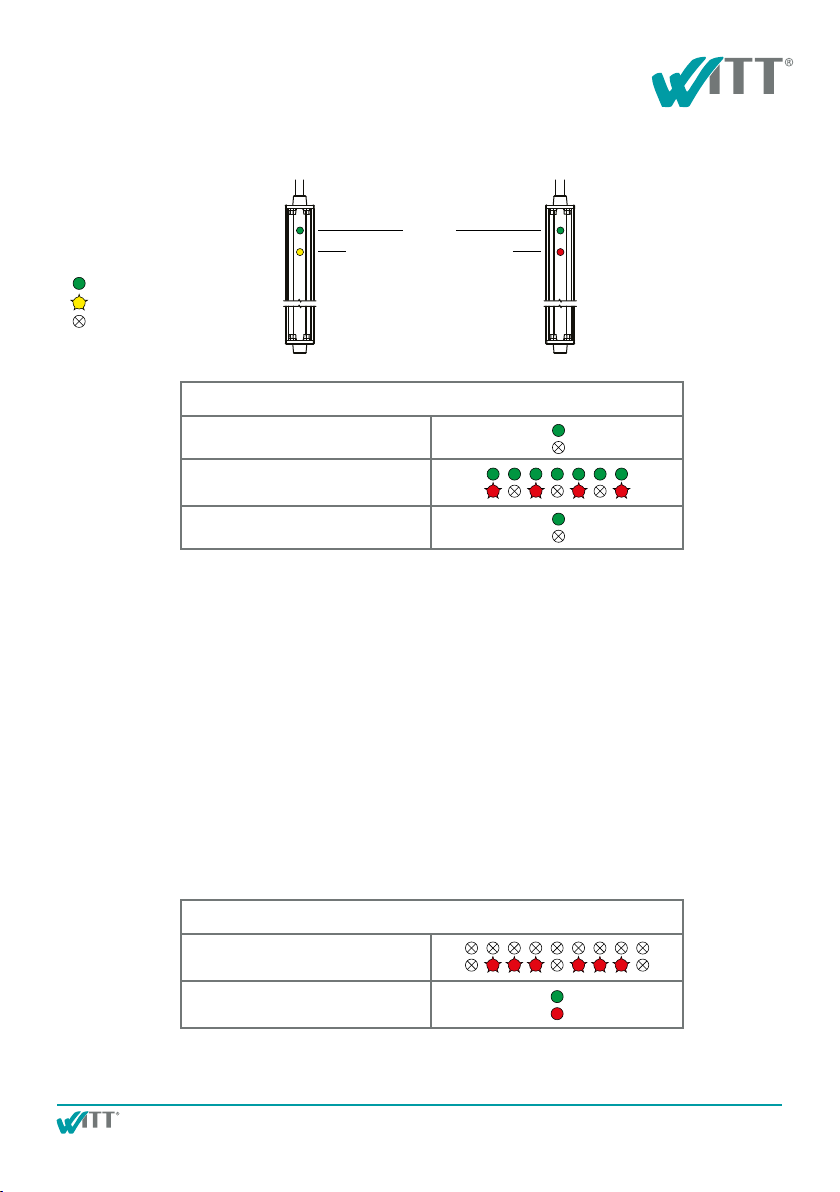
When installing PNP/NPN versions, it must be ensured that the door control system
checks the safety light curtain versions with a test input once per door cycle. To
do so, the control system must trigger the test input on the transmitter for at least
100ms and monitor the reaction behaviour of the output of the receiver. If the time
behaviour corresponds to the technical data, the test is successful. Testing by briefly
switching off the supply voltage is not suitable.
The safety light curtains are designed in such a way that sunlight and light from
halogen lamps and fluorescent tubes (see IEC 61496-2) do not lead to undesired
activation.
In rare cases, other photo switches or sources of infrared light can lead to undesired
activation. These sources of light interference must be dealt with in such cases by
switching off, blocking or removing them.
If two light curtains (in front of and behind the door) are to be used to provide
protection, the separation distance between the light curtain and door should be
small enough that persons cannot be present undetected between the door and the
detection zones that are created. For this application, the two transmitter of the light
curtains should be mounted on opposite sides of the door.

Sensoric
Sensoric GmbH Berlin © www.witt-sensoric.de 5
Sensoric
Mounting, installation and commissioning
Only one light curtain can be mounted in the door opening. In this case, the “door
function” of the light curtain prevents detection by the door itself.
When the light curtain is being mounted, it is to be placed on a stable subsurface.
Ensure that the ground is sufficiently level so that the sensor function can work at all
points.
Optical components (transmitters, receivers, LEDs) must not be covered.
A risk assessment in accordance with the machinery directive is the basis for deciding
on the selected safety method.
The alignment of the light curtain should be optimised after it has been mounted.
If the test input of the light curtain is activated for longer than 15s, the light curtain
switches into alignment mode. The signal reserve can be optimised in alignment
mode by alternately rotating the LIGI transmitter and LIGI receiver.
If the signal reserve is less than 2, the green receiver LED flashes in this mode. The
green LED remains on for signal reserves greater than 2 and the red receiver LED
flashes with increasing flash frequency when the signal reserve increases. The signal
reserve should be a factor of 2 or greater to ensure fault-free operation as well as to
tolerate a certain amount of dirt.
As soon as the test input is deactivated for a short period, the light curtain returns to
normal mode.
After installation and fine adjustment the light curtain should be switched off and
back on again before the performance test. The transmitter is than self adjusting the
optinum power.

Sensoric
Sensoric GmbH Berlin © www.witt-sensoric.de 6
Sensoric
Alignment mode:
This mode allows for optimum alignment of the LIGI based on a variable flash frequency of
the LEDs on the receiver.
Error messages:
The LIGI has an internal error diagnosis function which indicates errors by means of an LED
code depending on the type of error. In the event of an error, the LIGI switches to safe mode
and the door can then only be operated in “dead man” mode.
Electrical connection:
Operating mode
The connections are made depending on the version according to the supplied circuit
diagram.
Important note: The sync cable (white wire) is an internal connection between the
transmitter and receiver which must not be connected in the controller!
Transmitter
power supply = OK
blanking = off
power supply = OK
blanking = on
Test
(LEDs flashing alternately)
Receiver
Free detection zone
Interrupted detection zone
Test
(LEDs flashing alternately)
Legend
LED lit
LED flashing
LED off
green
yellow red
Transmitter
Receiver

Sensoric
Sensoric GmbH Berlin © www.witt-sensoric.de 7
Sensoric
Receiver
Excess gain less than 2 Green LED flashing
Excess gain greater
than 2
Flash frequency of red
LED increases with signal
reserve
Alignment mode
Alignment mode is accessed by activating test or alignment mode for at least 15s and for the
duration of alignment.
Rotating the transmitter and receiver increases or reduces the reception level. The more the
level increases, the faster the flash frequency of the red LED will be.
When the maximum flash frequency is reached, the light curtain is optimally aligned and can
be fastened in place.
For PNP or NPN output versions, the test input must now be disconnected from the fixed
potential again and connected to the test input of the controller.
The test input (T00 version) is only required for alignment when using the OSE output ver-
sions. Connect to 0V/GND in normal operation.
Transmitter
Alignment mode
(LEDs flashing alternately)
Legend
LED lit
LED flashing
LED off
green
yellow red
Transmitter
Receiver

Sensoric
Sensoric GmbH Berlin © www.witt-sensoric.de 8
Sensoric
Error mode
No supply voltage Check supply voltage
Receiver polarity
reversed
Yellow LED flashes 3x,
long pause
Check receiver
operating voltage
Short at output Red LED flashes 2x,
long pause
Check output cable,
overload, wrongly con-
nected, cable defective,
output on light curtain
defective
Error in sync cable Yellow LED flashes 3x,
long pause
Check sync cable
(white), may only be
connected between
transmitter and receiver
Internal device error All LEDs flashing Light curtain must be
replaced
Error mode
Legend
LED lit
LED flashing
LED off
green
yellow red
Transmitter
Transmitter
Receiver
Receiver

Sensoric
Sensoric GmbH Berlin © www.witt-sensoric.de 9
Sensoric
Light control
Installation steps (critical doors and floors / without door function):
For increased functional security when installing in front of the door, the reception signals
(reference values) must be programmed into the light curtain when the door is open and the
area to be protected is clear.
• The LIGI is installed as explained in the operating instructions, i.e. the transmitter is
connected as indicated in the table above (bottom row).
• When the door is open and the area to be protected is clear, the sync connection
between the transmitter and receiver is connected/hot-wired with 10-30 V DC
using a short filament for a very short period of time (less than 1s). Everything
else will now happen automatically.
• If the previous step has been carried out correctly, the green LED on the receiver will
be continuously on and the red LED will flash. The reference values will then be pro-
grammed. It is essential to keep the area to be protected clear during this time. This
programming process will take 10s and the red LED will then go out.
Installation options Notes Transmitter
connection
Installation at door level
(with door function)
Interruptions to the light beam in the door do
not lead to detection.
brown - 10-30 V DC
blue - 0 V/GND
Installation in front of door
noncritical standard doors
(without door function)
Door and floor have matt surfaces. brown - 0 V/GND
blue - 10-30 V DC
Installation in front of door
critical doors; critical floors
(without door function)
Critical points:
Part or all of the door has a highly reflective
surface.
Increased functional safety can be achieved by
programming the signals when the door is open
(see descriptions below).
brown - 0 V/GND
blue - 10-30 V DC

Sensoric
Sensoric GmbH Berlin © www.witt-sensoric.de 10
Sensoric
Receiver
Connect sync 15s to 25s with
10-30 V DC.
Connection to sync disconnected
again.
Installation and starting up with light control
Additional information:
• If something went wrong during the programming process explained above (e.g. accidental interruption
of light beam or if the adjustment was subsequently changed), the programming process can be
repeated as often as required.
• If the sync connection between the transmitter and receiver is connected with 10-30 V DC for
longer than 15s and less than 25s, all the saved reference values from the programming process
will be actively deleted, i.e. the factory settings are restored. Once the above connection has been
disconnected, the green and red LEDs on the receiver will illuminate for 2s; this confirms that the
reference values have been deleted. At this setting the light curtain is typically used for uncritical
ambient conditions.
Receiver
Area to be protected clear
Programming phase after connec-
tion for 1s
Programming phase complete
Legend
for 10s
for 2s
LED lit
LED flashing
LED off
Transmitter
Receiver
green
yellow red

Sensoric
Sensoric GmbH Berlin © www.witt-sensoric.de 11
Sensoric
The operation of the light curtain is to be tested as follows once it has been mounted.
1. A test rod with a diameter of 50mm must be continuously detected over a range
of 0mm to 300mm above the ground.
2. A test object with an edge length of 200mm must be continuously detected
over a range of 0mm to 2500mm above the ground. The test bodies should be
moved from bottom to top during these tests.
Top view:
Door and recommended light curtain layout of T=transmitter and R=receiver
R
T
T T
R R
Figure 2
With door function
(Blanking function)
Figure 1
Without door function
(Blanking function)
Testing

Sensoric
Sensoric GmbH Berlin © www.witt-sensoric.de 12
Sensoric
Maintenance and repair
The safety light curtain does not have any wearing parts that need to be maintained.
The light entry and exit openings are to be cleaned regularly, depending on the dirt
that occurs. Use a cloth with soapy water or a water jet for this purpose. High-pres-
sure cleaners, abrasives and organic solvents must not be used.
Check regularly whether the light curtains are correctly aligned. Adjust the alignment
if necessary. The light curtain casing, the optics areas, the plug and the connection
cable are to be checked regularly for damage. Parts with significant damage must be
replaced.
Furthermore please check detection ability on a regular basis as per manual page 11.
If light curtains are replaced, they must only be replaced by identical light curtains
or by other safety light curtains that are intended for the relevant door by the door
manufacturer.
Transmitter and receiver light curtains must only be replaced in pairs so as to ensure
that the same software and hardware status is present.
Repairs must only be carried out by trained personnel.
Versions
Number of channels: From 12 to 54 channels
Connection:
Connection cables 5m and 15m, the total length must not exceed 25m
Connection plug Pig-tail connector with M8 plug, 6-pin, L=130mm
Door function: Continuous interruption starting at the top light beam and going
towards lower light beams does not lead to detection as this
is interpreted as lowering of the door.

Sensoric
Sensoric GmbH Berlin © www.witt-sensoric.de 13
Sensoric
Technical data
Safety parameters ESPE type 2 as per IEC 61496-2
MTTFD> 100 years; DCAVG > 99% Category 2; PL d
(PFH=7.33.10-9 1/h) as per EN 61508-2;
Category 2 for LIGI-xx-Nxx and LIGI-xx-Pxx with only one
suitable external control system for testing
Door widths 1.6 to 10m
Rated voltage 24V DC -58% +25% (10 to 30V DC)
Current consumption Transmitter: Approx. 30mA (24V DC)
Receiver: Approx. 20mA (24V DC)
Power consumption Approx. 1.2W
Detection zone height Max. 2430mm (depending on channel count)
Channel count Max. 54
Type of light Modulated infrared
Type of switching: Light switching, i.e. the following applies for free detection zones:
OSE output = Alternating signal (approx. 950Hz)
PNP output = High level
NPN output = Low level
solid state relay SSR = low resistance
Aperture angle Approx. ±5°
Detection capability 0 to 300mm, detection object ≥ 50mm (version C)
300 to 2500mm, detection object ≥ beam separation
distance + 5mm
Door function max. door speed :
(Version A; end strip min. 100 mm) if max. door speed is 1.1 m/s
(Version A; end strip min. 125 mm) if max. door speed is 1.3 m/s
(Version C; end strip min. 370 mm) if max. door speed is 1.3 m/s
OSE output Approx. 950Hz, alternating signal, 4V 20mA, short proof,
reverse polarity protection, max. 100nF, max. 30µA leakage current,
integrated pull-down 220Ω
PNP output 100mA, short proof, reverse polarity protection, max. 220nF,
max. 350µA leakage current, integrated pull-down 10kΩ
NPN output 100mA, short proof, reverse polarity protection, max. 220nF,
max. 150µA leakage current, integrated pull-up 10kΩ
SSR output 100mA, short proof, max. 220nF, max. 30VDC, max. 21VAC
R on < 35Ω, leakage current < 100µA

Sensoric
Sensoric GmbH Berlin © www.witt-sensoric.de 14
Sensoric
Technical data
Testing
Reaction of the output after activation of the test input for a free detection zone
Test input
Variant Reaction of the output
P01 after max. 100ms switch from high to low level
N01 after max. 100ms switch from low to high level
OSE This version is not tested.
solid state relay SSR after max. 100ms change from
low resistance (<35Ω) to high resistance
Ambient light safety ≥100klux
Housing material Aluminium profile, fully filled, with 2K epoxy resin
Connection Pig-tail M8 plug 6-pin, L=130mm
Degree of protection IP67 as per EN 60529
Operating temperature -20 to +60°C
Storage temperature -30 to +70°C
Air humidity Max. 95%
Weight Approx. 1860g
Dimensions 2555x12x15mm (LxWxH)
(length applies to max. protective field height 2430mm)
Version Normal operation Test/alignment Internal input wiring
T00 <2V >7V 10kΩ pull-down resistor to 0V
T01 >7V <2V 10kΩ pull-down resistor to 0V
T02 <2V >7V 10kΩ pull-down resistor to 0V
T03 >7V <2V 10kΩ pull-up resistor to 24V
T04 <2V >7V 10kΩ pull-up resistor to 24V
T05 open 0V...4V or sup-
ply voltage -4V

Sensoric
Sensoric GmbH Berlin © www.witt-sensoric.de 15
Sensoric
Reaction of the output after deactivation of the test input for a free detection zone
Variante Reaction of the output
P01 after max. 100ms switch from low to high level
N01 after max. 100ms switch from high to low level
OSE This version is not tested.
solid state relay SSR after max. 100ms change from
high resistance to low resistance(<35Ω)
switching time Definition
t (turn on delay) ≤ 100ms light beam interruption
t (turn off delay) ≤ 800ms uninterrupted detection zone
Technical data

Sensoric
Sensoric GmbH Berlin © www.witt-sensoric.de 16
Sensoric
Connection scheme, OSE output
Connection scheme, SSR output
10...30VDC
0V/GND
test
not assigned
not assigned
sync
10...30VDC
0V/GND
OSE
not assigned
not assigned
sync
brown
blue
black
grey
pink
white
OSE = OSE-Ausgang
Sync = intere Verbindungsleitung zwischen Empfänger und Sender
Test = aktiv bei 10...30VDC
Transmitter Receiver
10...30VDC
0V/GND
Test-/Alignment input
not assigned
not assigned
Sync
10...30VDC
0V/GND
SSR output
SSR output
not assigned
Sync
brown
blue
black
grey
pink
white
0V/GND
10...30VDC
SSR = solid state relay
Sync = internal sync connection between transmitter and receiver
Test = active at 10...30VDC
brown
blue
Transmitter
(light-on switching)
Transmitter
(dark-on switching)
Receiver
light-on switching
dark-on switching
brown = -
blue
brown
blue
=+
= +
= -

Sensoric
Sensoric GmbH Berlin © www.witt-sensoric.de 17
Sensoric
+
+
T00 Adjustment=High level or switch closed
T01 Test=Low level or switch open
T02 Test=High level or switch closed
T03 Test=Low level or switch closed
T04 Test=High level or switch open
0V/GND
10...30V
10...30V test=high level
0V/GND test=low level
open=standard operation
Test input
Test input
LIGI
LIGI
LIGI
10kΩ
10kΩ
Connection scheme, test inputs T00, T01 and T02
Connection scheme, test inputs T03 and T04
Connection scheme, test input T05

Sensoric
Sensoric GmbH Berlin © www.witt-sensoric.de 18
Sensoric
Channel selection
45
45454545454545454545454545454545454545454545454545454545454545
45454545454545
7
1
1
8
4545
45
45
45
45
45
45
45
45
454545
4545
45
45454545454545454545454545454545454545454545454545454
545454545
45454545454545
7
1
1
8
45
45
45
45
45
45
45
45
45
45
454545
4545
2363 indicator LED
2363 indicator LED
2430 aktive detection zone (54 channels)
2430 aktive detection zone (20 channels)
2555 total length
2547 profile length
2547 profile length
2555 total length

Sensoric
Sensoric GmbH Berlin © www.witt-sensoric.de 19
Sensoric
Version A
Version C
45
45454545454545454545454545454545454545454545454545454545454545
45454545454545
7
1
1
8
4545
45
45
45
45
45
45
45
45
454545
4545
45
45454545454545454545454545454545454545454545454545454545454545
45454545454545
7
1
1
8
4545
45
45
45
45
45
45
45
45
454545
4545
45
454545454545454545454545454545454545454545454545454545
45454545
45454545454545
7
1
1
8
45
45
45
45
45
45
45
45
45
45
454545
4545

Sensoric
Sensoric GmbH Berlin © www.witt-sensoric.de 20
Sensoric
A-A ( 1.5:1 )
G ( 1.5:1 )
H ( 1.5:1 )
A
B
C C
D D
Weitergabe sowie Vervielfältiung dieser Unterlage,
Verwertung und Mitteilung ihres Inhalts nicht gestattet,
soweit nicht ausdrücklich zugestanden. Alle Rechte vorbehalten.
Copying of this document and giving it to others
and the use of communication of the contents thereof,
are forbidden without express authority. All rights reserved.
1
1
2
2
3
3
4
4
1 von1
A2
LIGI 07-55 Kanäle
LIGI 07 A 55
Ind. Aenderungen Datum Name
Gez.
Kontr.
Norm
Datum Name
10.03.2017
10.03.2017
pollak
Brech
Zeichnungs Nr./Drawing No.
Bezeichnung/Title
Material
Oberflaeche/Finish
Nicht tolerierte Maße
Free size tolerances
Alle Maße in mm
All dimensions mm
Gewicht/Weight
DIN ISO 2768
T1 m T2 K
Blatt/Sheet
. [g]
.
1:4,6
Maßstab/
Scale
.
01
02
03
04
05
06
07
08
09
10
.
.
.
.
.
.
.
.
.
.
.
.
.
.
.
.
.
.
.
.
.
.
.
.
.
.
.
.
.
Datei:LIGI 07 A 55.idw
Volumen/Volume . [mm³]
.
.
LIGI 07
.
G
H
Anzeige LED
7
22,5 22,5
2518
2510 -Profillänge-
24
2445
45
22,5
22,5
24 24
4545454545454545454545454545454545454545454545454545454545454545454545454545454545454545454545454545
970
1500
2152
2321 -Anzeige LED-
2388 -aktive Schutzfeldhöhe-55Kanäle-
7
15
12 4
10
45
45
24
7
22,5 22,5 24
970
1500
2152
2518
2510 -Profillänge-
123
display LED
display LED
12mm
15mm
16
16
max. 4
max. Ø 4mm
grün
rot
grün
gelb
Table of contents