WITTUR servogearless WSG-S1.5 User manual

eco
WITTUR Holding GmbH
Rohrbachstraße 26-30 • -85259 Wiedenzhausen, Germany
Tel. +49 (0) 81 34/18-0 • Fax +49 (0) 81 34/18-49
http://www.wittur.com, E-mail: info@wittur.com
servogearless
Gearless Lift Machine
WSG-S1.5
Operating Instructions
Code GM.8.003649.EN
ate 27.04.2016
Version 0.03
Page 1
Subject to changes without notice ! Subject to changes without notice !
EN
Gearless Lift Machines
WSG-S1.5
Reprinting, translation or reproduction in any form -
whether in part or in full - requires the prior written
permission of WITTUR Holding GmbH.
Wittur Holding GmbH reserves the right to make
changes in the information and pictures contained in
these operating instructions without prior notice.

Offenburger Str. 3
-01189 resden
Germany
Tel. +49-(0) 3 51-40 44-0
Fax +49-(0) 3 51-40 44-1 11
info.wed@wittur.com
www.wittur-edrives.de
Gearless Lift Machine
WSG-S1.5
Operating Instructions
Code GM.8.003649.EN
ate 27.04.2016
Version 0.03
Page 2
Subject to changes without notice ! Subject to changes without notice !
EN
These operating instructions are
applicable to lift machines:
WSG - S1.5 - ....
WITTUR Electric rives GmbH reserves the right to correct or
change the contents of this manual and these product details
without prior notice. We expressly reserve the right to make
technical changes which improve the lift machines or their
safety standards without prior notice. No liability can be
accepted for damage, injuries or expense arising therefrom.
We cannot guarantee the correctness and completeness of the
details.

Gearless Lift Machine
WSG-S1.5
Operating Instructions
Code GM.8.003649.EN
ate 27.04.2016
Version 0.03
Page 3
Subject to changes without notice ! Subject to changes without notice !
EN
Contents
1. General information............................................................................................................................4
1.1. About this operating manual . . . . . . . . . . . . . . . . . . . . . . . . . . . . . . . . . . . . . . . . . . . . . . . . . . . . . . . . . . .4
1.2. Intended use . . . . . . . . . . . . . . . . . . . . . . . . . . . . . . . . . . . . . . . . . . . . . . . . . . . . . . . . . . . . . . . . . . . . . . . . .4
1.3. Scope of delivery . . . . . . . . . . . . . . . . . . . . . . . . . . . . . . . . . . . . . . . . . . . . . . . . . . . . . . . . . . . . . . . . . . . . .4
1.4. Warranty and liability . . . . . . . . . . . . . . . . . . . . . . . . . . . . . . . . . . . . . . . . . . . . . . . . . . . . . . . . . . . . . . . . .4
2. Safety instructions...............................................................................................................................4
2.1. General . . . . . . . . . . . . . . . . . . . . . . . . . . . . . . . . . . . . . . . . . . . . . . . . . . . . . . . . . . . . . . . . . . . . . . . . . . . . .4
2.2. Format of the safety instructions . . . . . . . . . . . . . . . . . . . . . . . . . . . . . . . . . . . . . . . . . . . . . . . . . . . . . . . .5
2.3. Safety precautions . . . . . . . . . . . . . . . . . . . . . . . . . . . . . . . . . . . . . . . . . . . . . . . . . . . . . . . . . . . . . . . . . . . .5
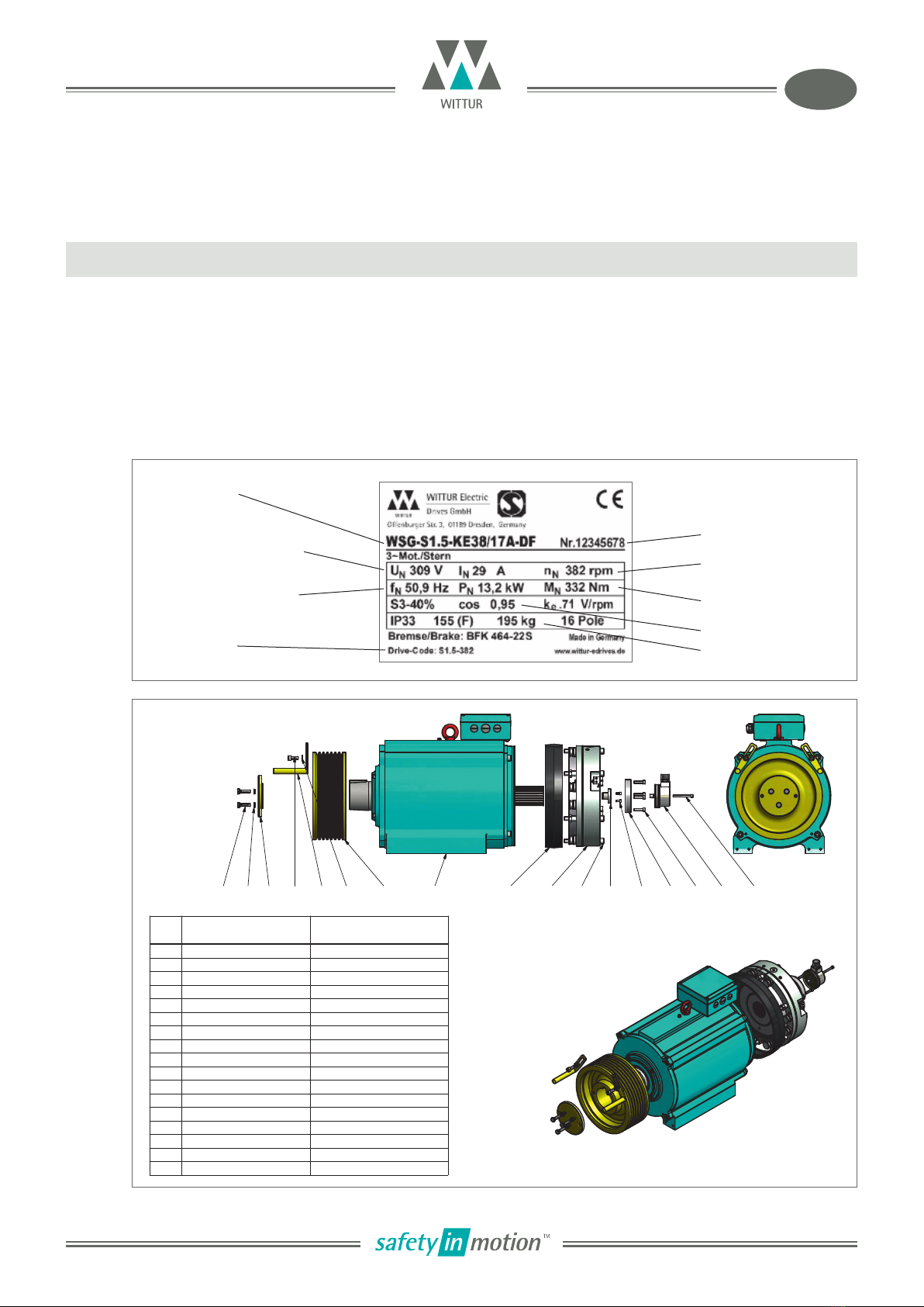
3. Product description ............................................................................................................................6
4. Transport and storage ........................................................................................................................7
5. Installation ..........................................................................................................................................8
5.1. Setting up . . . . . . . . . . . . . . . . . . . . . . . . . . . . . . . . . . . . . . . . . . . . . . . . . . . . . . . . . . . . . . . . . . . . . . . . . . .8
5.2. Electrical connection . . . . . . . . . . . . . . . . . . . . . . . . . . . . . . . . . . . . . . . . . . . . . . . . . . . . . . . . . . . . . . . . . .9
5.2.1. General . . . . . . . . . . . . . . . . . . . . . . . . . . . . . . . . . . . . . . . . . . . . . . . . . . . . . . . . . . . . . . . . . . . . . . . . .9
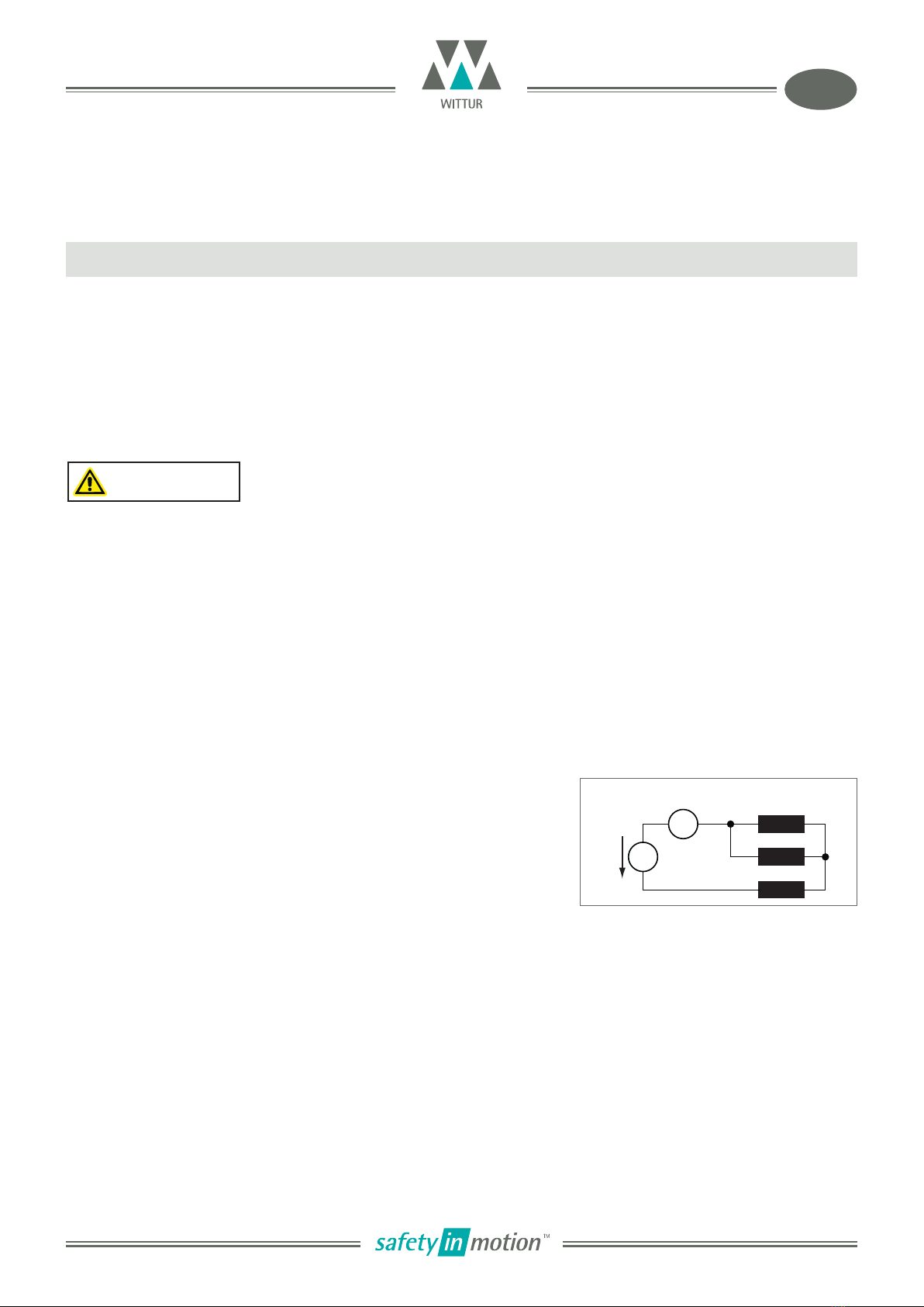
5.2.2. Motor connection / Winding protection . . . . . . . . . . . . . . . . . . . . . . . . . . . . . . . . . . . . . . . . . . . . .10
5.2.3. Speed/Position measuring system . . . . . . . . . . . . . . . . . . . . . . . . . . . . . . . . . . . . . . . . . . . . . . . . . .12
5.2.4. Brake . . . . . . . . . . . . . . . . . . . . . . . . . . . . . . . . . . . . . . . . . . . . . . . . . . . . . . . . . . . . . . . . . . . . . . . . . .13
6. Commissioning ..................................................................................................................................17
7. Operation and maintenance ..........................................................................................................18
7.1. General . . . . . . . . . . . . . . . . . . . . . . . . . . . . . . . . . . . . . . . . . . . . . . . . . . . . . . . . . . . . . . . . . . . . . . . . . . . .18
7.2. Maintenance intervals . . . . . . . . . . . . . . . . . . . . . . . . . . . . . . . . . . . . . . . . . . . . . . . . . . . . . . . . . . . . . . .18
7.3. Regreasing the bearings . . . . . . . . . . . . . . . . . . . . . . . . . . . . . . . . . . . . . . . . . . . . . . . . . . . . . . . . . . . . . .19
7.4. Replacing the traction sheave . . . . . . . . . . . . . . . . . . . . . . . . . . . . . . . . . . . . . . . . . . . . . . . . . . . . . . . . .19
7.5. Emergency evacuation . . . . . . . . . . . . . . . . . . . . . . . . . . . . . . . . . . . . . . . . . . . . . . . . . . . . . . . . . . . . . .20
7.6. Testing the brake system to EN 81-1 . . . . . . . . . . . . . . . . . . . . . . . . . . . . . . . . . . . . . . . . . . . . . . . . . . . .21
7.7. Replacing the measuring system . . . . . . . . . . . . . . . . . . . . . . . . . . . . . . . . . . . . . . . . . . . . . . . . . . . . . . .22
7.8. Trouble shooting . . . . . . . . . . . . . . . . . . . . . . . . . . . . . . . . . . . . . . . . . . . . . . . . . . . . . . . . . . . . . . . . . . . .23
8. Type code.............................................................................................................................................24
9. Technical data ....................................................................................................................................25
10. Dimension drawing............................................................................................................................26
11. Accessories..........................................................................................................................................27
11.1. Connecting cable for measuring systems . . . . . . . . . . . . . . . . . . . . . . . . . . . . . . . . . . . . . . . . . . . . . . . .27
11.2. Cable set for motor and brake . . . . . . . . . . . . . . . . . . . . . . . . . . . . . . . . . . . . . . . . . . . . . . . . . . . . . . . . .28
11.3. Brake manual release . . . . . . . . . . . . . . . . . . . . . . . . . . . . . . . . . . . . . . . . . . . . . . . . . . . . . . . . . . . . . . . .29
11.4. Rope guards . . . . . . . . . . . . . . . . . . . . . . . . . . . . . . . . . . . . . . . . . . . . . . . . . . . . . . . . . . . . . . . . . . . . . . . .30
12. Spare parts .........................................................................................................................................31
Annex
EU eclaration of Conformity
Calculation of the traction sheave shaft
Traction sheave shaft
Calculation of the traction sheave shaft (traction sheave: 160 mm)
Traction sheave shaft (traction sheave: 160 mm)
EU type-examination certificate EU-B 975
Brake operating instructions

Gearless Lift Machine
WSG-S1.5
Operating Instructions
Code GM.8.003649.EN
ate 27.04.2016
Version 0.03
Page 4
Subject to changes without notice ! Subject to changes without notice !
EN
1. General information
2. Safety instructions
2.1. General
WSG-S1 lift machines are not ready-to-use products; they may only be operated after they have been installed
in lift systems and their safe operation has been ensured by taking the appropriate measures.
WSG-S1 lift machines are intended for use in an enclosed, lockable operating area to which only qualified
personnel and personnel authorised by the customer have access.
1.1. About this operating manual
The purpose of this operating manual is to ensure that any work on WSG-S1 lift machines is carried out safely.
Please regard it as part of the product and keep it within easy reach.
All persons working on or with WSG-S1 lift machines must have read and understood this operating manual.
1.2. Intended use
WSG-S1 lift machines are intended for use as gearless drives for rope lifts. They may only be used for their
intended purpose and with all safety devices in proper working order.
They may only be operated under the conditions described in this manual and with due regard to their perform-
ance limits.
1.3. Scope of delivery
The WSG-S1 lift machines are customised to meet individual requirements. The exact scope of delivery can be
found in the accompanying documentation.
1.4. Warranty and liability
Our "Conditions of Sale and elivery" shall apply for all our supplies and services.
Any warranty claims must be made immediately upon discovery of the deficiency or defect.
We do not accept any warranty or liability claims for personal injury or property damage resulting from one or
more of the following causes
• Improper use of the WSG-S1 lift machine
• Improper installation, commissioning, operation or maintenance
• Operation of the WSG-S1 with defective and/or inoperative safety or protective devices
• Non-compliance with the instructions contained in the operating manual or other documentation supplied
• Unauthorised construction modifications to the WSG-S1
• Insufficient monitoring of parts subject to wear
• Repairs carried out improperly
• Emergencies caused by external forces or force majeure

Gearless Lift Machine
WSG-S1.5
Operating Instructions
Code GM.8.003649.EN
ate 27.04.2016
Version 0.03
Page 5
Subject to changes without notice ! Subject to changes without notice !
EN
Qualified personnel
Only qualified personnel are authorised to perform any planning, installation or maintenance work, and this
must be done in accordance with the relevant instructions. The personnel must be trained for the job and must
be familiar with the installation, assembly, commissioning and operation of the product.
2.2. Format of the safety instructions
The safety instructions contained in this operating manual are presented in a standardised format.
They comprise a danger symbol + signal word + instruction text. The danger symbol indicates the type of dan -
ger, the signal word specifies the severity of the danger, and the instruction text describes the danger and
explains how to avoid it.
Danger symbols
Signalworte
•DANGE Serious injuries or death will result
•WA NING Serious injuries or death may result.
•CAUTION Minor to moderate injuries may result.
•NOTICE Property damage may result.
•Information Points out useful information.
2.3. Safety precautions
• Check the proper functioning of the motor and the brake after installing the machine.
• Repairs may only be carried out by the manufacturer or an authorised repair agency. Unauthorised opening
and tampering may result in injuries to persons and property.
• The machines are not designed for direct connection to the three-phase system but are to be operated via an
electronic frequency converter. irect connection to the mains may damage the motor beyond repair.
• High surface temperatures may occur on the external parts of the machine. Therefore, no temperature-sensi -
tive parts may be in contact with these parts or attached to them. Protection against accidental contact
should be provided, if required.
• The EU type-examined fail-safe brakes provided are designed only for a limited number of emergency brak-
ing operations. They must not be used as working brakes.
• If the motor is not energised, no torque is produced. This may result in uncontrolled acceleration of the lift,
if the brakes are released. Therefore, the motor winding should be short-circuited to produce a speed-depen -
dent braking torque while the motor is not supplied with current. (Use the main contacts for short-circuiting
as rated motor current may be flowing.) The motor must never be short-circuited while it is energised.
• High voltages are present at the terminal connections during the operation of synchronous motors.
Risk of electric shock Property damage
General danger Information

1 2 3 5 7
46 8 11 910 12 13 14 15 16 17
cos
Gearless Lift Machine
WSG-S1.5
Operating Instructions
Code GM.8.003649.EN
ate 27.04.2016
Version 0.03
Page 6
Subject to changes without notice ! Subject to changes without notice !
EN
The compact gearless WSG-S1 synchronous lift machines are designed for traction sheave lifts. They are distin-
guished by their high efficiency, extremely low noise and excellent operating characteristics.
The machines can be supplied for several rated speeds, which can be further adapted to meet individual cus -
tomer requirements. The machine comprises a frame, the synchronous motor, the traction sheave, and the
type tested safety brake, which can be used to prevent uncontrolled upward movement of the car.
The nameplate of the lift machine is on the motor frame.
3. Product description
Type code of lift
machine
Rated voltage Rated speed
Rated torque
Serial no.
Rated frequency
Weight
rive-Code
Item Part WSG-S1.5
1 Bolts (3x) M8x30 - 10.9
2 Lock washers (3x) NL 8- IN 25201
3 Pressure disc
4 Bolts (2x) IN 912 - M8x20
5 Rope slip-off guard
6 Washers (2x) IN 125 - A 8,4
7 Traction sheave
8 Frame
9 Brake BFK 464-22S
10 Bolts (6x) IN 912 M 10 x 110
11 Locking ring
12 Plug-in shaft
13 Screws (3x) IN 912 - M 4x10
14 Clamping sleeve
15 Screws (4x) IN 912 - M 6x25
16 Measuring system
17 Cylinder-head screw IN 912 M 5x50

u
v
w
A
I≈45% IN
-
U
Gearless Lift Machine
WSG-S1.5
Operating Instructions
Code GM.8.003649.EN
ate 27.04.2016
Version 0.03
Page 7
Subject to changes without notice ! Subject to changes without notice !
EN
4. Transport and storage
• The lift machines leave the factory in perfect condition after being tested.
• Make a visual check for any external damage immediately upon their arrival on site. If any damage is found
to have occurred in transit, make a notice of claim in the presence of the carrier. If appropriate, do not put
these machines into operation.
• Observe the relevant safety regulations and take the centre of gravity into account when handling the lift
machines.
• Check that the eyebolts are tightly fitted before using them.
• o not expose the motor to any shocks or impact.
Storage
• Store the motors only in closed, dry, dust-free, well-ventilated and vibration-free rooms (storage tempera -
ture: -20°C to 60°C). o not store lift machines in the open air. Bright parts are not sufficiently preserved to
withstand extended periods of exposure.
• Avoid excessive storage periods (recommendation: max. one year).
• After prolonged storage (>3 months), rotate the motor in both directions at a low speed (< 20 min-1) to
allow the grease to distribute evenly in the bearings.
• Measure the insulation resistance before initial operation of the machine. If the value has dropped below
1kper volt of rated voltage, the winding needs to be dried (insulation meter voltage: 1,000 V C).
• This can be done, for instance, with hot air, in a drying oven, or by applying a C voltage to the motor con-
nections. Make sure that the voltage selected does not exceed the values shown in the figure " rying the
winding". Let the temperature rise to about 70 – 80°C and maintain it for several hours.
WA NING The eyebolts are designed for the specified machine weight, i.e. additional loads must not be
applied. anger of breakage!
Drying the winding
Unpacking
• ispose of the packaging material in an environmentally friendly manner or reuse it.
• Any special transport aids or shipping braces are left with the customer.

ok
ü
ok
ü
ok
üok
üok
üok
ü
Gearless Lift Machine
WSG-S1.5
Operating Instructions
Code GM.8.003649.EN
ate 27.04.2016
Version 0.03
Page 8
Subject to changes without notice ! Subject to changes without notice !
EN
5. Installation
5.1. Setting up
• The machines can be used in lift systems with or without a machine room
• The permissible uneveness of the mounting surface is 0.1 mm. The mounting surface must be sufficiently dis -
tortion-resistant and stable to accommodate the forces occurring in the system.
• The rope force can be applied to the lift machine in any direction
• The machine must be mounted on vibration dampers for vibration damping
• No welding work may be performed on the lift machine, nor is it permissible to use the machine as a mass
point for welding work. This might cause irreparable damage to the bearings and magnets.
• If there are more grooves on the traction sheave than the number of ropes used, position the ropes either in
the centre of the traction sheave or towards the motor end.
DANGE Be sure to use calculations to check the base frame or foundation loads before installing the
lift machine.
WA NING Cover the machine and especially the brakes when doing any machining or dust-producing
work in the shaft or machine room.
When using the machine in a shaft, please take into account the patent situation.
• The measuring system is only accessible from the rear side. Therefore, leave enough space between the wall
and the rear side of the machine or ensure that the machine can be moved away from the wall.
Securing the machine
• Fasten the machine using 4 M 20 bolts - strength class 8.8; tightening torque: 395Nm .
• After completing the adjusting work or after a breakdown, tighten all the fastening bolts of the machine,
using the specified torque .
• Lift machines are generally equipped with rope slip-off guards. After putting the ropes in place, adjust them
so that the distance between the rope and the rope slip-off guard does not exceed 1.5 mm.
• If the lift machine is not installed at the head of the machine room as is usually the case, it may be necessary
to modify the fitting of the rope slip-off guard to fulfill the requirements of EN 81-20 . Optional rope slip-off
guards are available for this purpose.

0,6
0,7
0,8
0,9
1,0
1,1
1,2
0102030405060
Gearless Lift Machine
WSG-S1.5
Operating Instructions
Code GM.8.003649.EN
ate 27.04.2016
Version 0.03
Page 9
Subject to changes without notice ! Subject to changes without notice !
EN
Ambient conditions
• The following ambient conditions must be ensured
on site
Altitud: max. 1,000 m a.s.l.
Ambient temperature: -5°C ... 40 °C
Max. rel. humidity: 85% at 20°C
(no moisture condensation)
• Install the machine so that ventilation is not obstruct ,
ed, i.e. sufficient heat dissipation by convection and
radiation must be ensured.
• The torque and power values indicated in the techni cal
data apply to the above ambient temperatures and
altitudes. In the case of a deviating altitude and/or
temperature, the reduction factors k shown in the dia-
gram "Ambient conditions" must be used.
Mpermiss = k * MN
Ppermiss = k * PN
Ambient temperature [°C]
Factor k
Altitude < 1000 m
Altitude < 2000 m
Altitude < 3000 m
5.2. Electrical connection
5.2.1. General
• Before starting any work on the machines, ensure that the lift machine or system is properly isolated.
Before making any electrical connections check that
• the connecting cables are suitable for their specific application and for the relevant voltages and currents.
• sufficiently dimensioned connecting cables, torsion, strain and shear relief, as well as anti-kink protection are
provided
• the protective conductor is connected to the earthing terminal
• there are no foreign bodies, dirt or moisture in the terminal boxes
• cable entries not in use and the terminal box itself are tightly sealed to prevent the ingress of dust or
splash ing water.
CAUTION The insulation system of the motors is designed such that they can be connected to a con-
verter with a maximum C link voltage Ulink max up to max. 700 V C.
Ulink max is the maximum value of the C link voltage which is only transient and approxi -
mately equivalent to the inception voltage of the braking chopper or of the energy recovery
unit.
The maximum permissible rate of voltage rise (dU/dt) at the motor terminals is 4kV/µs. The
overvoltage at the motor terminals must not exceed 1.56 kV. It may be necessary to use
motor current filters or reactors to achieve these values.
WA NING The electrical connection may only be made by a qualified electrician.

M
Pin Signal
1 U1
A
B
C
D
1
2
3
4
2 PE
3 W1
4 V1
A
B
C
Gearless Lift Machine
WSG-S1.5
Operating Instructions
Code GM.8.003649.EN
ate 27.04.2016
Version 0.03
Page 10
Subject to changes without notice ! Subject to changes without notice !
EN
5.2.2. Motor connection / Winding protection
• The electrical connection of the motor and the winding sensors is made in the terminal box, by power con -
nector or by cable (standard length: 5 m).
• The motor cable must be shielded. Ensure that the cable shield contacts the frame over a large area at both
ends.
• The motor phases U1, V1 and W1 must be connected correctly to the corresponding phases of the converter;
they must not be interchanged.
• We recommend using a converter with a switching frequency of 12 kHz.
• The PTC resistor embedded in the winding must be evaluated in an appropriate manner in the control system
or the frequency converter to protect the motor from overheating.
1. Terminal box2. Plug connection
not assigned
not assigned
temperature
sensor
Blick auf die Stiftkontakte
der Anschlussdose (von
außen)
temperature
sensor
As an option, the electrical connection of the
motor and the winding temperature sensors
is made by a rotatable 8-pole power connec-
tor provided on the motor. A type B ST A 078
FR 05 08 0035 000 connector from
"intercontec" can be used, for example, as
the female plug.
WAGO 262
Cable cross-section: ... 4 mm2
Stripping length required: 9-10 mm
Triplet PTC
Type STM-150. S...
Screw plugs 2 xM16 and 1 xM20
2xM16 Cable gland
for cable diameter 5-10 mm
M 20 Cable gland
for cable diameter 7-12 mm

3 x 4000
3 x 1330
3 x 550
3 x 250
-20°C
130°C
145°C
150°C
155°C
165°C
M
PE
U1
V1
W1
T1
T2
U1 / 1
V1 / 2
W1 / 3
T1 / 5 / BR1
T2 / 6 / BR2
Gearless Lift Machine
WSG-S1.5
Operating Instructions
Code GM.8.003649.EN
ate 27.04.2016
Version 0.03
Page 11
Subject to changes without notice ! Subject to changes without notice !
EN
Short-circuiting the motor terminals
• The motor terminals of the synchronous lift machines, type WSG, can be short-circuited, if required, to brake
the lift machine faster.
• However, this is only permissible at speeds less than or equal to the rated speed of the respective motor.
PTC thermistors
The maximum operating voltage of the PTC thermis -
tors is not allowed to exceed 25 V C
To achieve the maximum precision, the
measurement voltage per PTC thermistor must not
exceed 2.5 V C.
Cable cross-section required:
The currents specified under the machine data refer to duty type S3-40%. This must be taken into account
when selecting the cable cross-section required. The continuous r.m.s. value required for the selected cable is
approximated from:
I r.m.s. (cable). »I N (motor, S3-40%) / 1,58
The table on the right gives the standard values for
the current-carrying capacity of PVC cables at a
maximum ambient temperature of 40°C.
Cable cross-
section
required
Permissible max.
current
(r.m.s. value)
Permissible max.
motor current IN
(S3 - 40%)
1.0 mm213.1 A 20.7 A
1.5 mm215.7 A 24.8 A
2.5 mm222.6 A 35.7 A
4.0 mm229.6 A 46.7 A
3. Cable connection
Core marking
triplet PTC
shield
green/yellow
Ferrules
Temperatur [°C]
Widerstand []

Gearless Lift Machine
WSG-S1.5
Operating Instructions
Code GM.8.003649.EN
ate 27.04.2016
Version 0.03
Page 12
Subject to changes without notice ! Subject to changes without notice !
EN
Measuring system ECN 413
Number of sine-cosine
periods per rotation: 2048
Operating voltage: 5V
ata interface:: SSI or EN AT
Measuring system Sendix 8.5873
Number of sine-cosine
periods per rotation: 2048
Operating voltage: 5V
ata interface: BISS
Ader Signal
weiß 0 V (Up)
braun Up
grün Clock +
gelb Clock -
grau ATA +
rosa ATA -
blau SET
rot IR
schwarz A +
violett A -
grau-rosa B +
rot-blau B -
Schirm shield
Pin Signal
1 UpSensor
11
5
6
7
13
9
8
10 16
17
15 14
12 2
1
4
3
4 0 V Sensor
7 Up
8 Clock +
9 Clock -
10 0 V (Up)
11 inner shield
12 B +
13 B -
14 ATA +
15 A + Pin contacts of flanged con -
nector socket (exterior)
16 A -
17 ATA -
5.2.3. Speed/Position measuring system
• The basic version of the lift machines is equipped with an sendix 8.5873 SineCosine encoder from Kübler
GmbH. The encoder is connected by cable (length: 10m) with open wire ends (no plug).
• Alternatively, the machines can be equipped with ECN 413 or ERN 487 encoders (from Heidenhain GmbH). We
can also provide other measuring systems on request.
• Use a shielded cable to connect the Heidenhain measuring systems to the converter system. We recommend
the use of our cable sets, which can be supplied as an accessory.
CAUTION The measuring system of WSG lift machines with a
synchronous motor (WSG) is matched to the associat ed
converter. o not change the adjustment, as this may
make it impossible to use the motor. On the measur-
ing system housing there is a label showing the "offset
angle" and the inverter type.
The offset angle depends on the converter used.

Gearless Lift Machine
WSG-S1.5
Operating Instructions
Code GM.8.003649.EN
ate 27.04.2016
Version 0.03
Page 13
Subject to changes without notice ! Subject to changes without notice !
EN
5.2.4. Brake
• Please refer also to the operating instructions for the brake.
• The brakes are supplied with C voltage by the overexcitation rectifiers, which are supplied separately or in
the terminal box.
• Only the overexcitation rectifiers which are included in our scope of supply are to be used for the brake acti-
vation.
• The terminals for the brake coils and for the monitoring contacts are provided in a terminal box or on the
plug connector.
• Repeated switching of the brake magnets during the overexcitation period must be avoided as this will result
in overloading of the brake control unit. Therefore, a minimum brake operating time of approx. 1.5 – 2 s
should be maintained, especially during an inspection or commissioning drive.
• To reduce the switch-off time, switching can be effected from the C side. However, switching must also be
performed from the AC side at the same time ! (Wiring with a varistor as shown in the circuitry suggestion
on page 16!)
Note on the use of DC/AC side switching:
AC side switching is recommended for normal operation, since the lift machine is then decelerated in a con-
trolled manner to zero speed and the switching noise of the brake is negligible.
When braking in the event of a breakdown (emergency stop) or during an inspection drive, the switching
should be performed from the C side, since this ensures a faster braking effect with the car being stopped
earlier. We therefore recommend the use of 2 separate contactors for the brake control circuitry, one of
which switches at the C side, the other at the AC side.
AC side switching
• Low-noise switching of the brake
• No protective measures required for switching
con tact
• Slow application of the brake.
DC side switching
• Noisy switching
• Burn-up protection for switching contact required
(e.g. varistor, free-wheeling diode)
• Fast application of the brake.
~
+
-
Br
-
+
Br
~
Attention: schematic diagram! Attention: schematic diagram!

C
NC
NO
C
NC
NO
Gearless Lift Machine
WSG-S1.5
Operating Instructions
Code GM.8.003649.EN
ate 27.04.2016
Version 0.03
Page 14
Subject to changes without notice ! Subject to changes without notice !
EN
Monitoring the brakes
• The switching states of the brakes are monitored by means of dust-proof microswitches with gold contacts.
Both the n.c. and the n.o. contact connections are available.
Connection of the brakes
The brake solenoids, the brake control units and the monitoring contacts are connected to the mains in the
terminal box, by power connector or by cable (standard length: 5 m).
WA NING The microswitches must be evaluated separately for each partial brake to ensure compliance
with the requirements of the type examination.
1. Terminal box
Option: terminal box
without brake control
unit
WAGO 262
Cable cross-section: ... 4 mm2
Stripping length required: 9-10 mm
„release“ 2nd. partial brake
Screw plugs 2 xM16 and 1 xM20
2xM16 Cable gland
for cable diameter 5-10 mm
M 20 Cable gland
for cable diameter 7-12 mm
„release“ 1st. partial brake
1st. partial
brake
2nd. partial
brake
blue
grey
black
blue
grey
black

AA
3
A
3
EA
3
E
2A
3
E
2
C
A
3
E
2
C
D
A
3
E
2
C
D
EA
3
E
2
C
D
E
B
A
3
E
2
C
D
E
B
1
A
3
E
2
C
D
E
B
1
1
2
3
A
B
C
D
E
PIN
1
2
3
4
5
6
7
8
Gearless Lift Machine
WSG-S1.5
Operating Instructions
Code GM.8.003649.EN
ate 27.04.2016
Version 0.03
Page 15
Subject to changes without notice ! Subject to changes without notice !
EN
2. Plug connection
3. Cable connection
As an option, the electrical connection
of the brake made by a 9-pole power
connector mounted on the brake. A
type B ST A 908 FR11 85 001A 000
connector from "intercontec" can be
used, for example, as the female plug.
1st. partial brake
2nd. partial brake
1st. partial brake
2nd. partial brake
grey
blue
black
blue
grey
black
blue
black
1st. partial brake
2nd. partial brake
1st. partial brake
2nd. partial brake
grey
blue
black
blue
grey
black
blue
black
Core marking
Ferrules

WSG-S1.5
230 V ±10%
40...60 Hz
6 -
5 +
4
3
2 ~
1 ~
intorq
BEG-561...
K1
{
K1
NC
NO C
{
NC
NO C
intorq
BEG-561...
6 -
5 +
4
3
2 ~
1 ~
2
3
C
E
D
2
3
C
E
D
u
S10 K275
u
S10 K275
K2
Gearless Lift Machine
WSG-S1.5
Operating Instructions
Code GM.8.003649.EN
ate 27.04.2016
Version 0.03
Page 16
Subject to changes without notice ! Subject to changes without notice !
EN
Circuitry suggestion for brake control WSG-S1.5
Circuitry suggestion for brake control
C side switching and separate control of
the partial brakes
AC side switching and separate control of
the partial brakes
K1 and K2 must swith simultaneously .
Brake connector
2 x Overexcitation rectifier
(Must be installed in the
contol cabinet.)
to the 2nd. partial brake
Brake connector
Brake connector
Brake magnet
Brake magnet
to control cabinet
release
to control cabinet
release
1st. Partial brake
1st. Partial brake
Brake monitoring
Brake monitoring
grey
blue
black
grey
blue
black

Gearless Lift Machine
WSG-S1.5
Operating Instructions
Code GM.8.003649.EN
ate 27.04.2016
Version 0.03
Page 17
Subject to changes without notice ! Subject to changes without notice !
EN
6. Commissioning
The following points should be checked or completed:
• Check that all performance and application data specified on the name plate of the machine are consistent
with your application.
• Have all securing, auxiliary and installation tools been removed from the danger area?
• Check that the lift machine is being used for its intended purpose – comply with the permissible ambient
conditions.
• Check that the lift machine has been properly fastened with the fastening bolts – have the bolts been tight-
ened to the specified torque and secured?
• Has the motor been properly connected, including the motor protection? Has the PE terminal been properly
connected? Is the potential equalisation with the machine frame ensured?
• Check the brake connection and the proper functioning of the brake monitoring switches.
• Ensure that the brake operates correctly; perform a brake test using one partial brake.
• Has the measuring system been properly connected?
• Is the measuring system properly connected?
• Check that the offset value indicated on the measuring system agrees with the value set on the converter.
• Check the proper functioning of the brake; perform a braking test using one partial brake.
• Is the rope slip-off guard properly tightened and adjusted?
An initial function test of the motor and the brake, together with the converter, should be performed before
the ropes are put in place.
If the motors are being operated at no shaft load (no ropes put in place) for an extended period of time,
abnormal noise may occur resulting from the bearing type used
If the motor winding is short-circuited with the control system deactivated, a speed-dependent braking
torque will be produced, even at low speeds. Therefore, the short-circuiting should be deactivated during the
half-load test. It is imperative for it to be reactivated after the test.
Half-load test

Gearless Lift Machine
WSG-S1.5
Operating Instructions
Code GM.8.003649.EN
ate 27.04.2016
Version 0.03
Page 18
Subject to changes without notice ! Subject to changes without notice !
EN
7. Operation and maintenance
7.1. General
• The regulations concerning operation, maintenance and inspection pursuant to the applicable safety regula -
tions for lift construction such as IN EN 81-20, IN EN 81-50, L 2014/33/EU and other relevant regulations
are to be strictly observed.
• The operator is responsible for ensuring that the motor is installed properly and in accordance with the safe -
ty requirements, as well as for its inspection and maintenance as specified in the applicable regulations.
• The proper maintenance of gearless lift machines requires adequately trained specialist personnel and special
devices and tools.
• Repairs other than those described in these operating instructions are not to be carried out by the lift fit -
ter/maintenance technician for liability reasons.
Bolt/screw tightening torques
• When performing any work on the machine or
replacing parts, make sure that the specified
bolt/screw strength class and the tightening
torques are observed (see table).
• Secure the bolts/screws with "omnifit 100" or a
similar product against accidental loosening.
7.2. Maintenance intervals
Dimension Tightening torque [Nm]
Strength class 8.8 10.9 12.9
M4 2,8 4,1 4,8
M5 5,5 8,1 9,5
M6 9,6 14 16
M8 23 34 40
M10 46 67 79
M12 79 115 135
M16 195 290 340
M20 395 560 660
M24 680 970 1150
Check the brake air gap every six months see the brake operating instructions
Check the proper functioning of the brakes and the
brake monitoring switches every six months see the brake operating instructions
Check the bearing noise every six months
Regrease the bearings see section 7.3
Check the traction sheave for wear every six months
Make a visual check of the fasteningbolts/screws on
the frame, brake and traction sheave every six months see section 7.1
Check the electrical cables every six months see section 5.2.
Check the rope slip-off guard every six months
Check the guards and safety devices for their condi-
tion and safe functioning every six months
Clean the external machine surfaces as required

1
2
4
3
5
3
6
1
Gearless Lift Machine
WSG-S1.5
Operating Instructions
Code GM.8.003649.EN
ate 27.04.2016
Version 0.03
Page 19
Subject to changes without notice ! Subject to changes without notice !
EN
7.3. egreasing the bearings
The anti-friction bearings have been provided with a grease filling at the factory that is sufficient for the
planned service life of the machine. Under normal operating conditions, regreasing is not required or recom -
mended.
7.4. eplacing the traction sheave
WA NING The traction sheave can work loose if it is not properly installed.
Necessary tools
• Hoisting equipment • Spacer (4...7 mm)
• Torque wrench (M 8) • Cleaning cloth
Disassembly
• isconnect the system and safeguard against accidental
restarting.
• Secure the car and the counter-weight.
• Remove the rope slip-off guards and the rope guards, if
provided.
• Relieve the load on the traction sheave; remove the
ropes.
• Support the traction sheave by means of a hoisting
gear.
• Remove the three M 8 bolts (1) at the pressure disc and
the pressure disc itself.
• Insert two fastening bolts (2) into the outer hole circle
of the pressure disc (3) and into the traction sheave.
• Insert a 4-7 mm spacer (4) between the pressure disc
and the shaft journal.
• Pull off the traction sheave from the tapered shaft
seats by tightening the bolts evenly.
Assembly
• Clean the traction sheave and the motor shaft.
• Support the traction sheave by means of a hoisting
gear.
• Insert the feather key (5) into the shaft end.
• Slide the traction sheave onto the motor shaft.
• Fit the pressure disc (3) to the traction sheave and fasten
it using three pairs of NOR -LOCK washers (6) and
M8x30-10.9 bolts (1). Tighten the bolts alternately
around the circle in three torque steps (10, 20 and
34 Nm) as far as they will go. Tightening torque: 34 Nm
• Replace the ropes and reinstall the rope slip-off guard.

~ 800 N
Gearless Lift Machine
WSG-S1.5
Operating Instructions
Code GM.8.003649.EN
ate 27.04.2016
Version 0.03
Page 20
Subject to changes without notice ! Subject to changes without notice !
EN
7.5. Emergency evacuation
Manually operated evacuation in case of emergency
• The brakes can be opened manually by using the lifting levers (option)
• Two different options can be chosen (shown in the following pictures):
DANGE All actions for evacuation in case of emergency have to be done by qualified service
personnel.
WA NING When the evacuation is finished, the initial state has to be restored. Especially the
lever extensions have to be removed.
Manual lifting rods (machine room): Brake manual release remotelly controlled:
• Is the brake opened manually, the cabin moves in the direction of the higher weight. In case of balance, the
cabin has to be weighted down with suitable additional mass.
• The motor winding has to be short-circuited via the motor contactors. With the short circuit the motor cre -
ates a brake torque, which is dependent on the motor speed. This prevents an uncontrolled acceleration of the
elevator.
• It is possible that the brake torque which is created by the motor short circuit is not enough to limit the
speed of the elevator. Therefore the cabin speed has to be observed carefully during the evacuation and if
needed, the evacuation has to be stopped.
• When the cabin has reached the next floor, the manually opened brake is closed again. The rescue of the
trapped persons in the cabin can begin.
Electrically operated evacuation in case of emergency
• The electrical opening of the brakes is done using the power grid or an UPS.
• The operating instructions of the controller, the inverter or the evacuation unit with UPS have to be fol lowed!
Eyebolts
Lever extension
elease
elease
Table of contents
Other WITTUR Lifting System manuals

WITTUR
WITTUR Beamer 2 Series User manual

WITTUR
WITTUR WSG-W8 Series User manual

WITTUR
WITTUR WSG-TB.3 series User manual

WITTUR
WITTUR WSG-10 Operating instructions

WITTUR
WITTUR WRG80 User manual

WITTUR
WITTUR servogearless WSG-S2.3 User manual

WITTUR
WITTUR WSG-SF Series User manual

WITTUR
WITTUR WGG-29.1 User manual

WITTUR
WITTUR OL35E-NA User manual

WITTUR
WITTUR WSG-18 Series User manual