Wize PRG11A-W User manual

1
ВНИМАНИЕ!
ВНИМАНИЕ! ТРАВМА И ПОВРЕЖДЕНИЕ ОБОРУДОВАНИЯ МОЖЕТ ПРОИЗОЙТИ ОТ
НЕПРАВИЛЬНОЙ УСТАНОВКИ ИЛИ СБОРКИ. ОЗНАКОМЬТЕСЬ СО СЛЕДУЮЩИМИ
ПРЕДУПРЕЖДЕНИЯМИ ПЕРЕД НАЧАЛОМ.
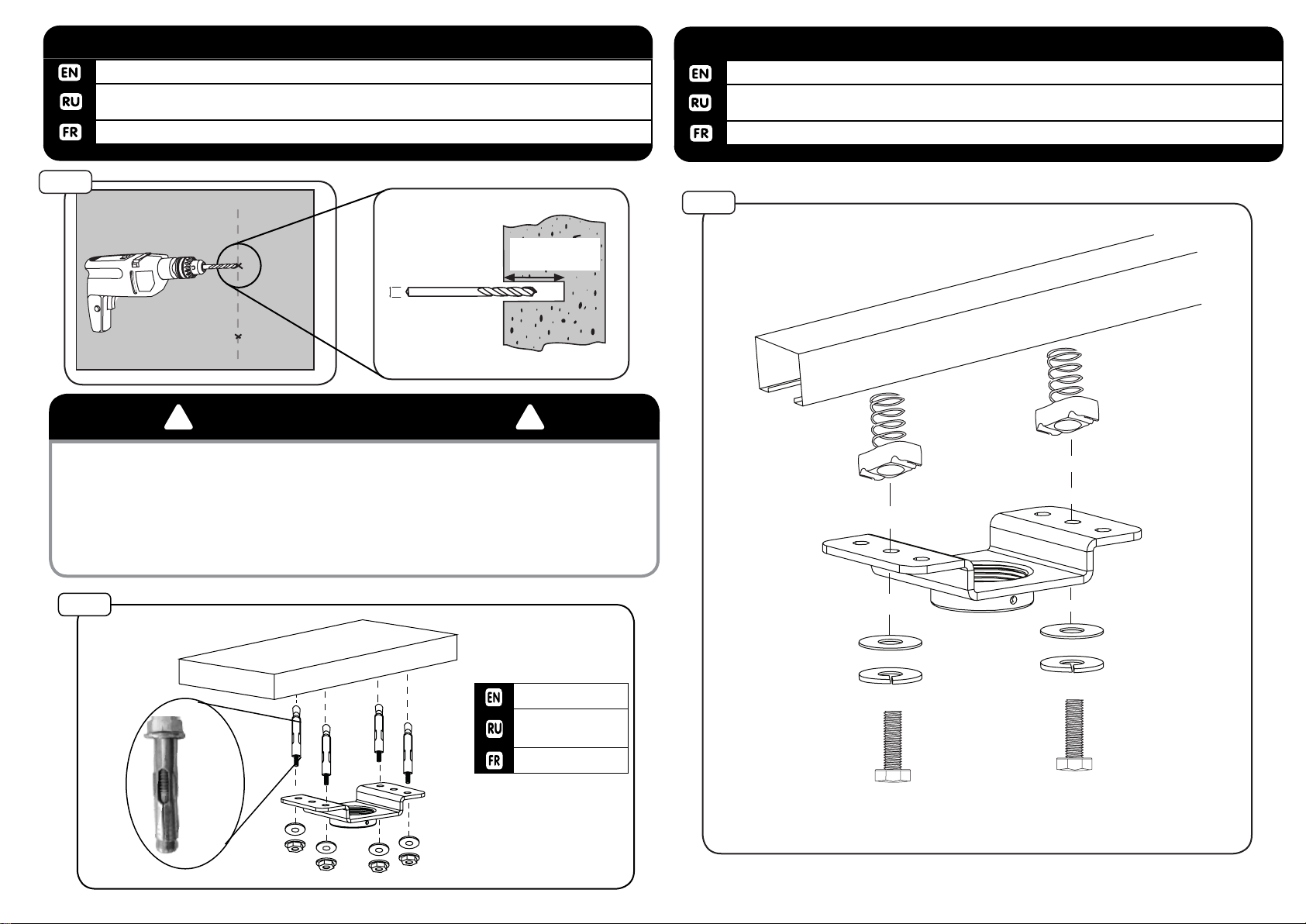
Компоненты, входящие в этот продукт, предназначен для установки на стенах из цельного
дерева, бетона или бетонных блоков. Для стен из других материалов, таких как кирпич,
пожалуйста, проконсультируйтесь с
вашим инсталлятором и / или специалистом поставщика.
НЕ ПРЕВЫШАЙТЕ МАКСИМАЛЬНЫЙ ВЕС, УКАЗАННЫЙ В ИНСТРУКЦИИ
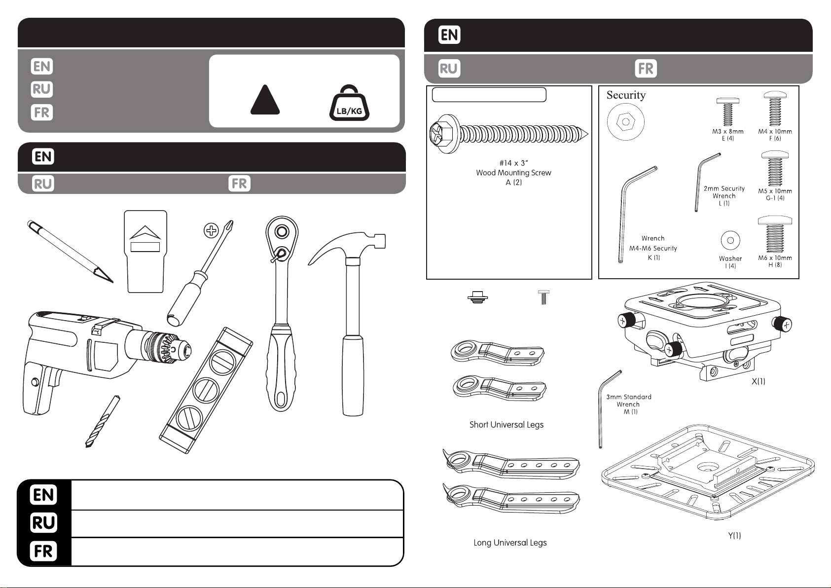
Manuel D’instructionsИнструкция
Instruction Manual
Универсальное проекторное крепление
Макс. вес нагрузки: 31 кг
www.wize-av.ru [email protected]
! !
WARNING! SEVERE PERSONAL INJURY AND PROPERTY DAMAGE CAN RESULT FROM
IMPROPER INSTALLATION OR ASSEMBLY. READ THE FOLLOWING WARNINGS BEFORE
BEGINNING.
Do not use this product for any purpose not explicitly specied by Wize. Improper installation may
cause property damage or personal injury. If you do not understand these directions, or have doubts
about the safety of the installation, contact Wize Customer Service or call a qualied contractor. Wize
is not liable for damage or injury caused by incorrect mounting, assembly, or use.
e hardware provided with this product, is exclusively intended for installation on surfaces made of
solid wood or concrete, with a maximum of 16 mm of drywall. For surfaces made of other materials,
for example hollow bricks, please consult your installer and/or specialist supplier.
DO NOT EXCEED THE MAXIMUM WEIGHT CAPACITY FOR THIS PRODUCT
WARNING! AVERTISSEMENT! SI CE PRODUIT N’EST PAS CORRECTEMENT INSTALLÉ OU ASSEMBLÉ,
IL RISQUE DE CAUSER DES BLESSURES RAVES, VOIRE MORTELLES, AINSI QUE DES DOM-
MAGES MATÉRIELS IMPORTANTS. AVANT DE COMMENCER, LISEZ LES AVERTISSEMENTS
SUIVANTS.
N’utilisez pas ce produit à une n non spéciée expressément par Wize. Une installation incorrecte
peut entraîner des préjudices corporels ou des dommages matériels. Si vous ne comprenez pas ces
instructions ou si vous avez des doutes quant à la sécurité de l’installation, veuillez contacter le service
clientèle de Wize ou un installateur qualié. Wize n’est pas responsable des dommages ou des préju-
dices causés par un montage, un assemblage ou une utilisation incorrects.
Le matériel fourni avec ce produit, est exclusivement destiné à être installé sur des murs en bois mas-
sif, en béton, blocs de béton ou des colonnes en bois massif avec un maximum de 16 mm de plaques
de plâtre. Pour les murs faits d’autres matériaux, comme la brique creuse, s’il vous plaît consulter votre
installateur et / ou fournisseur spécialisé.
NE DÉPASSEZ JAMAIS LA CAPACITÉ DE CHARGE MAXIMALE DE CE PRODUIT.
AVERTISSEMENT
PRG11A(-W/S), PRG18A (-W/S), PRG24A (-
W/S), PRG35A (-W/S), PRG47A (-W/S)

2
!
WEIGHT CAPACITY
Maximum Weight Capacity
Poids maximal de l’écran
0
70lb / 31.7kg
CAUTION!
TOOLS REQUIRED
Outils nécessaires
PACKAGE CONTENTS
Contenu de l’emballage
PR3XL
Необходимые Инструменты
Входит в комплект
Wood bit 4mm - 5/32”. Masonary bit 8mm - 5/16”. Socket wrench
3/8” and 13mm. Hammer if necessary.
Сверло для дерева 4 мм - 5 / 32 “. Сверло для бетона 10 мм - 3 / 8 “.
Молоток при необходимости.
Peu de bois de 4 mm - 5/32”. peu maçonnerie 8m - 5/16”. 3/8” et
13mm Clé à douille. Marteau si nécessaire. Universal Plate
PR3 body
Zl(4)
Zs(4)
Leg Connector
B(4)
Screw
C(4)

3
(M)
(F)
drill depth
65mm / 2.5”
drill diameter
4mm
5/32”
WOOD JOIST INSTALLATION
1a-1
1a-2
INSTALLATION INSTRUCTIONS
PACKAGE CONTENTS
Contenido del paquete Contenu de l’emballage
PACKAGE CONTENTS
Contenu de l’emballage
GG
(1)
FF
(1)
A
AA
HH
(1)
II
(1)
Security
EE
(4)
DD
(4)
B
S
F
Входит в комплект Инструкция
Ensure that holes are on center of wood joist.
Убедитесь, что отверстия в центре деревянной балки.
Veiller à ce que les trous sont au centre des solives de bois.
1a
Instructions d’installation
Use a 4mm - 5/32” wood bit to make a 65mm / 2.5” deep hole on marks.
Используйте 4 мм - 5 / 32 “ сверло для дерева, чтобы высверлить отверстие 65 мм /
2.5” глубины по меткам.
Utilisez un 4mm - 5 / 32” bits du bois pour faire un 65mm / 2.5” trou profond sur les marques.
WOOD JOIST INSTALLATION1a-1

4
1b-1
drill depth
32mm / 1.25”
drill diameter
8mm
5/16”
1c-1
Use a 8mm - 5/16” masonry bit to make a 32mm / 1.25” deep hole on marks.
Используйте 8мм -5/16“ сверло, чтобы высверлить отверстия 32 мм / 1.25” глубины по
меткам.
Utilisez un 8mm-5/16” bits de maçonnerie pour faire un 32mm/1.25” trou profond sur les marques.
1b-1 STRUCTURAL CONCRETE INSTALLATION
Attach to unistrut using kit HU2
Присоединить к потолку, используя комплект HU2
Installer le sur Unistrut. HU2 Utiliser le kit de matériel.
1c-1 UNISTRUT INSTALLATION
! !
Install only to structural concrete ceiling, with density of at least 2000psi.
Устанавливайте только к структурному бетонному потолку, с плотностью не менее 2000 фунтов
на квадратный дюйм.
IInstallez seulement sur les surfaces de structure, faite de béton avec une densité d’au moins 2000psi.
WARNING!
1b-2
(F)
(HE516)
Expansion anchors not
included (order kit HE516)
Бетонные крепежи
не входят в
комплект.
Ordonnance sur les lieux
pour HE516

5
OR
O
OU
(EE)
(DD)
(II)
(HH)
OR
o
ou
(FF)
(GG)
A
AA
(S)
(I)
2-4
OR
O
OU
(EE)
(DD)
2-1 2-2
2-3
Slide column (A) into column (AA). Adjust to desired length. Lock into place with securing screws. read
column into ceiling adapter.
Вставьте штангу(А) в штангу (AA). Отрегулируйте до нужной длины. Зафиксируйте на место с
крепежными винтами.
Se glisser la colonne (A) dans la colonne (AA). Ajuster à la longueur désirée. Lock en place avec des vis. En-
ler de colonne dans l’adaptateur de plafond.
2 ASSEMBLE ADJUSTMENT COLUMN

6
Determine the correct leg length needed. Attach all four legs to the projector utilizing
the provided screws. Leave screws loose - do not tighten until step # 1-4.
.
. .
Déterminer la longueur de la jambe correcte nécessaire. Fixez les quatre pieds au
projecteur en utilisant les vis fournies. Laissez les vis lâches - ne serrez pas jusqu’à
l’étape n° 1-4.
3-1 PREPARE PROJECTOR FOR MOUNTING
(E-H)
(K-L)
Adjust the levelers to clear obstructions and level all legs.
Réglez niveleurs filetées. Aligner la hauteur de chaque pied.
PREPARE PROJECTOR FOR MOUNTING3-2
Attach the universal plate (Y) to the universal legs (Z)
(Y) (Z)
Fixer la plaque universelle (Y) et les pattes universelles (Z)
PREPARE PROJECTOR FOR MOUNTING3-3
Make sure that arrows point in same direction as the lens, then tighten screws.
, .
Assurez-vous que les flèches pointant dans la même direction que l’objectif, puis serrez les vis.
PREPARE PROJECTOR FOR MOUNTING3-4
(H)
(K)

7
Some projectors have only one attachment point. In this case, attach directly to the
universal plate.
.
.
Certains projecteurs ont un seul point d’attache. Dans ce cas, se fixent directement
sur la plaque universelle.
3-5 PREPARE PROJECTOR FOR MOUNTING
(E-H)
4-1 INSTALL PROJECTOR BODY (EXTENSION PIPE)
Thread the PR3 body (X) on the extension with the arrows pointing to the screen.
Enfilez le corps PR3 sur (X) l’extension avec les flèches pointant à l’écran.
Extension
pipe
Arrow points to screen
Screen
4-2 INSTALL PROJECTOR BODY (EXTENSION PIPE)
Tighten the locking set screw.
.
Serrer la vis de blocage.
4-3 INSTALL PROJECTOR BODY (EXTENSION PIPE)
Run the wiring through the pipe and through the PR3 body.
Exécuter le câblage à travers le tube et à travers le corps PR3.
Screen
JKR311824-0001
PR3 , , .
PR3 .

8
Slide the universal plate into the PR3 body from right to left (while facing screen).
Hold the wires up to prevent interference.
Glisser la plaque universelle dans le corps PR3 de droite à gauche (en faisant
face écran). Maintenir les fils en place pour éviter les interférences.
5-1 INSTALL PROJECTOR
Screen
Tighten pre-installed thumb screw and attach at least one of two retaining screws (J)
on the opposite side of the housing.
Serrer la vis à oreilles pré-installé et fixer au moins une des deux vis de fixation (J) Sur
le côté opposé du boîtier.
5-2 INSTALL PROJECTOR
Screen
(J)
(K)
PR3 .

9
roll
pitch
yaw
SCREEN
6-1 MAKE ADJUSTMENTS-YAW
Adjust the yaw by turning the knob labeled “yaw”
Réglez le lacet en tournant le bouton étiqueté “lacet”
6-2 MAKE ADJUSTMENTS-PITCH
Adjust the pitch by turning the knob labeled “pitch”
Réglez la hauteur en tournant le bouton étiqueté “pitch”
SCREEN
roll
pitch
yaw
JKR311824-0001
RU
RU
“yaw” ” “pitch”

10
6-3 MAKE ADJUSTMENTS-ROLL
Adjust the roll by turning the knob labeled “roll”
Réglez le rouleau en tournant le bouton étiqueté “rouler”
SCREEN
roll
pitch
Tighten the pitch and roll lock screws, then, if required, use pitch and roll knobs to
micro adjust the image.
Serrer la vis de blocage de tangage et de roulis, puis, si nécessaire, utilisez les bou-
tons de tangage et de roulis de micro-réglage de l’image.
7LOCK AND MICRO-ADJUST
yaw
roll
yawroll
pitch
SCREEN
SCREEN
pitch lock
roll lock
pitch
JKR311824-0001
“roll”
, ,
.
RU
RU

11
Wize!
, .
Wize 10- .
.
RU RU
Congratulations on the purchase of this Wize product! e product you now have in your possession is
made of durable materials and is based on a design, every detail of which has been meticulously thought-
out. at is why Wize products are covered by a 10-year warranty against defects in materials or manufac-
turing.
Wize disclaims any liability for modications, improper installations, or installations over the specied
weight range. To the maximum extent permitted by law, Wize disclaims any other warranties, expressed
or implied, including warranties of tness for a particular purpose and warranties of merchantability.
Wize will not be liable for any damages arising out of the use of, or inability to use, Wize products. Wize
bears no responsibility for incidental or consequential damages. is includes, but is not limited to, any
labor charges for the repair of Wize products performed by anyone other than Wize.
Specications are subject to change without prior notice.
WARRANTY
Nous vous félicitons pour l’achat de ce produit Wize! Vous venez d’acquérir un produit réalisé
à partir de matériaux durables et d’une conception ingénieuse jusque dans les moindres détails.
Wize est ainsi en mesure de garantir ses produits pendant 10 ans contre les défauts de matéri-
aux et de fabrication.
Wize rejette toute responsabilité relativement à quelque problème pouvant être associé à une
modication d’un produit, à une mauvaise installation ou à une installation ne respectant pas
les limites de charge. Sous réserve des lois en vigueur, Wize réfute toute autre garantie expresse
ou implicite, notamment toute garantie de commercialisation ou de convenance à un usage
quelconque. Wize réfute toute responsabilité pour des dommages résultant de l’utilisation
ou de l’impossibilité d’utiliser des produits Wize. Wize réfute également toute responsabilité
pour quelque dommage accessoire ou indirect. Ceci s’applique notamment aux frais de main
d’oeuvre pour la réparation de produits Wize par une personne ne travaillant pas pour Wize.
Les spécications sont sujettes à changement sans préavis.
GARANTIE
WARRANTY CONTINUED
www.wize-av.com
This manual suits for next models
14
Table of contents
Other Wize Projector Accessories manuals
Popular Projector Accessories manuals by other brands

peerless-AV
peerless-AV Modular Series installation instructions

NorthVision
NorthVision VisionShare manual

SVS
SVS 12EX LIFT installation instructions

Orei
Orei WHD-PRO2T-K user manual

Digital Projection
Digital Projection Projector Controller user guide

Elite Screens
Elite Screens Portable Mobile Stand user guide