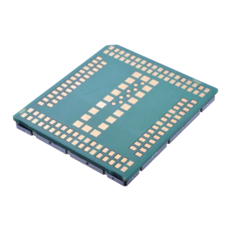
WNC IMQ6 User manual

1/37
User Manual
□Normal □Internal Use Confidential □Restricted Confidential
User Manual
Project Name: IMQ6 Module
Author: Wistron NeWeb Corporation
Revision: 0.3
Revision Date: 2020/11/28

2/37
User Manual
□Normal □Internal Use Confidential □Restricted Confidential
Contact Information
Technical Support website
https://SupportIoT.wnc.com.tw
Company Website
www.wnc.com.tw
Revision History
Rev. #
Author
Summary of Changes
Date
0.1
WNC
First release
2020/09/15
0.2
WNC
Update Safety Recommendation
2020/11/10
0.3
WNC
Update Safety Recommendation
2020/11/28

3/37
User Manual
□Normal □Internal Use Confidential □Restricted Confidential
© Wistron NeWeb Corporation
THIS DOCUMENT AND THE INFORMATION CONTAINED HEREIN IS PROPRIETARY AND IS THE
EXCLUSIVE PROPERTY OF WNC AND SHALL NOT BE DISTRIBUTED, REPRODUCED, OR
DISCLOSED IN WHOLE OR IN PART WITHOUT PRIOR WRITTEN PERMISSION FROM WNC.
LIMITATION OF LIABILITY
THIS DOCUMENT AND THE INFORMATION CONTAINED HEREIN IS PURELY FOR DESIGN
REFERENCE AND SUBJECT TO REVISION BY WNC AT ANY TIME. NOTHING IN THIS
DOCUMENT SHALL BE CONSTRUED AS GRANTING ANY WARRANTY OR RIGHT TO USE THE
MATERIAL CONTAINED HEREIN WITHOUT WNC’S PRIOR EXPRESS WRITTEN CONSENT. WNC
SHALL NOT BE LIABLE FOR ANY USE, APPLICATION OR DEVELOPMENT DERIVED FROM THE
MATERIAL WITHOUT SUCH PRIOR EXPRESS WRITTEN CONSENT.

4/37
User Manual
□Normal □Internal Use Confidential □Restricted Confidential
Contents
Contact Information................................................................................................................. 2
Revision History........................................................................................................................ 2
Contents.................................................................................................................................... 4
1. Introduction.......................................................................................................................... 6
1.1. RF band support........................................................................................................6
1.2. Features.................................................................................................................... 6
1.3. Architecture.............................................................................................................. 7
1.4. Connection Interface................................................................................................ 7
1.5. Environmental Specifications and Certifications...................................................... 7
1.5.1. Environmental Specifications........................................................................7
1.5.2. Certifications................................................................................................. 8
1.5.3. Green Product Compliance........................................................................... 8
2. Pin Definitions...................................................................................................................... 8
2.1. LGA Module Pin Diagram..........................................................................................8
2.2. LGA Module Pin Definitions......................................................................................9
3. Electrical Specifications...................................................................................................... 14
3.1. Power supply...........................................................................................................14
3.2. RF Specifications.......................................................................................................15
3.2.1. Band support...............................................................................................15
3.2.2. Bandwidth support..................................................................................... 16
3.2.3. RF transmit specifications........................................................................... 16
3.2.4. RF receiver specifications............................................................................17

5/37
User Manual
□Normal □Internal Use Confidential □Restricted Confidential
3.2.5. GNSS receiver specifications....................................................................... 18
4. Software Interface.............................................................................................................. 18
4.1. Support tools.......................................................................................................... 18
4.2. USB interface.......................................................................................................... 18
5. Mechanical..........................................................................................................................19
5.1. PCBA Form Factor................................................................................................... 19
6. Design Guide.......................................................................................................................22
6.1. Power supply...........................................................................................................22
6.2. RF connection......................................................................................................... 23
6.3. Reflow..................................................................................................................... 26
7. Labeling and Packaging...................................................................................................... 29
7.1. Labeling...................................................................................................................29
7.2. Packaging................................................................................................................ 29
7.3. MSL level.................................................................................................................31
8. Safety Recommendation.................................................................................................... 32
Initialisms................................................................................................................................36

6/37
User Manual
□Normal □Internal Use Confidential □Restricted Confidential
1. Introduction
The WNC IMQ6 module includes the Qualcomm MDM9205 Cat. M1 baseband, a complete
LTE RF front-end, memory, and required circuitry to fulfill requirements of 3GPP E-UTRA
(Long Term Evolution - LTE, Rel-14 specifications). The IMQ6 module provides a variety of
interfaces including USB, SPI, UART, GPIO, I2C, and USIM.
1.1. RF band support
This section lists the main features and functions that the IMQ6 module supports. Table 1-1
specifies wireless technologies supported.
Module
LTE CAT M1
LTE CAT NB2
GPRS/EGPRS
GNSS
IMQ6
√
×
√
√
Table 1-1. IMQ6 module overview
Note: √= supported, ×= not supported
1.2. Features
Feature list:
LTE 3GPP release 14
3GPP category support: LTE Cat. M1 with 1.2 Mbps for UL, 375 Kbps for DL
LTE Support Bands:B2/3/4/5/12/13/20
Power Class 5: 21dBm
GNSS: GPS, GLONASS
Cortex A7 microprocessor (performance enhanced)
IPv4/IPv6-supported
AT command set
LwM2M, FOTA

7/37
User Manual
□Normal □Internal Use Confidential □Restricted Confidential
SMS over NAS
Interfaces
HS USB 2.0 with integrated PHY
Dual UART interfaces (4 bit and 2 bit) for data transfer and diagnostic tools
I2C/SPI interface
USIM interface
GPIOs
ADC
PCM/I2S
1.3. Connection Interface
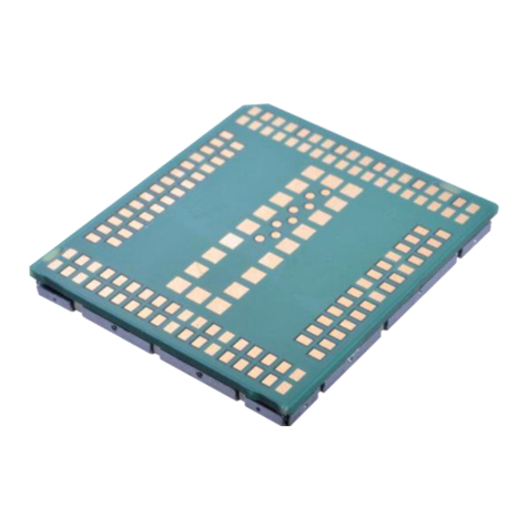
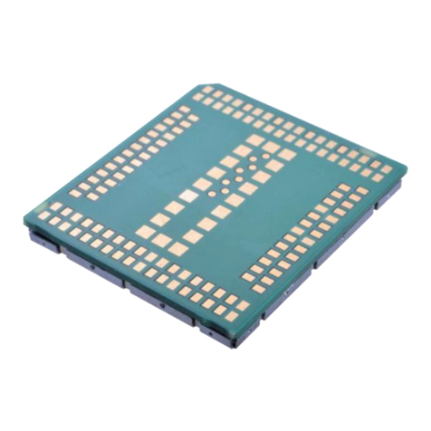
The IMQ6 module is LGA device. All electrical and mechanical connections are made
through the 104 pads on the bottom side of a PCB.
1.4. Environmental Specifications and Certifications
1.4.1. Environmental Specifications
The environmental specifications for both operating and storage conditions are defined in
the Table below.
Condition
Temperature Range
Remark
Normal operating
temperature range
–20 °C to 60 °C
Fully functional and in compliance with 3GPP
specifications
Extended operating
temperature range
–40 °C to 85°C
RF performance may be affected outside the
normal range, but the module will still function.
Storage
–40 °C to 85 °C
Table 1-2. Temperature range

8/37
User Manual
□Normal □Internal Use Confidential □Restricted Confidential
Note: All temperatures above refer to ambient temperatures.
1.4.2. Certifications
The IMQ6 module is certified to be compliant with PTCRB, GCF,CE,FCC
regulations and standards.
1.4.3. Green Product Compliance
RoHS (2011/65/EU)
2. Pin Definitions
2.1. LGA Module Pin Diagram
The IMQ6 LGA module pin layout is illustrated below.

9/37
User Manual
□Normal □Internal Use Confidential □Restricted Confidential
Figure 2-1. LGA pad diagram (top view)
2.2. LGA Module Pin Definitions
A complete list with related details for the module pinout are listed in the Table below:
Pin No.
Pin definition/type
Voltage Level (V)
Min.
Typ.
Max.

10 /37
User Manual
□Normal □Internal Use Confidential □Restricted Confidential
7
GND
-
0
-
8
GND
-
0
-
9
NC
-
-
-
10
GND
-
0
-
11
GND
-
0
-
12
GND
-
0
-
13
GND
-
0
-
14
GND
-
0
-
15
RF_1(LTE TRX)
-
-
-
16
GND
-
0
-
17
GND
-
0
-
18
GND
-
0
-
19
GND
-
0
-
20
GND
-
0
-
21
RF_2(GNSS)
-
-
-
22
GND
-
0
-
23
GND
-
0
-
24
GND
-
0
-
25
GND
-
0
-
26
GND
-
0
-
27
NC
-
-
-
28
GND
-
0
-
29
GND
-
0
-

11 /37
User Manual
□Normal □Internal Use Confidential □Restricted Confidential
30
GND
-
0
-
37
VCC1
3.3
3.8
4.5
38
VCC2
3.3
3.8
4.5
39
VCC3
3.3
3.8
4.5
40
VCC4
3.3
3.8
4.5
41
VCC5
3.3
3.8
4.5
42
VCC6
3.3
3.8
4.5
43
NC
-
-
-
44
GND
-
0
-
45
GND
-
0
-
46
GPIO46
1.7
1.8
1.9
47
GPIO47
1.7
1.8
1.9
48
GPIO48
1.7
1.8
1.9
49
GPIO49
1.7
1.8
1.9
50
GND
-
0
-
51
GND
-
0
-
52
GPIO01
1.7
1.8
1.9
53
GPIO02
1.7
1.8
1.9
80
GPIO80
1.7
1.8
1.9
81
GPIO81
1.7
1.8
1.9
82
GPIO82
1.7
1.8
1.9
83
GPIO83
1.7
1.8
1.9
84
GND
-
0
-

12 /37
User Manual
□Normal □Internal Use Confidential □Restricted Confidential
85
GND
-
0
-
86
USB_Dp
-
Note6
-
87
USB Detect
1.7
1.8
1.9
88
USB_Dn
-
Note6
-
89
UART2_RTS
1.7
1.8
1.9
90
NC
-
-
-
91
UART2_CTS
1.7
1.8
1.9
92
UART0_CTS
1.7
1.8
1.9
93
UART0_TX
1.7
1.8
1.9
94
UART2_TX
1.7
1.8
1.9
95
UART0_RX
1.7
1.8
1.9
96
UART2_RX
1.7
1.8
1.9
97
UART0_RTS
1.7
1.8
1.9
98
GPIO98
1.7
1.8
1.9
99
GPIO99
1.7
1.8
1.9
100
GPIO100
1.7
1.8
1.9
101
GPIO101
1.7
1.8
1.9
102
GPIO102
1.7
1.8
1.9
103
GPIO103
1.7
1.8
1.9
130
GPIO06/vGPIO Data In/AUX_ADC1
1.7
1.8
1.9
131
GPIO07
1.7
1.8
1.9
132
GNSS_EN/GPIO08
1.7
1.8
1.9
133
UIM_VCC/1.8V
1.7
1.8
1.9

13 /37
User Manual
□Normal □Internal Use Confidential □Restricted Confidential
134
UIM DATA
1.7
1.8
1.9
135
UIM CLK
1.7
1.8
1.9
136
UIM RESET
1.7
1.8
1.9
137
UIM DETECT
1.7
1.8
1.9
138
RFFE3_CLK/GPIO138
1.7
1.8
1.9
139
GND
-
0
-
140
RFFE3_DATA/GPIO140
1.7
1.8
1.9
141
WWAN_STATE
1.7
1.8
1.9
142
Power on
1.7
1.8
1.9
143
WAKEUP_OUT
1.7
1.8
1.9
144
WAKEUP_IN
1.7
1.8
1.9
145
RESET
1.7
1.8
1.9
146
VREF
1.7
1.8
1.9
208
SPI_EN
1.7
1.8
1.9
209
SPI_CLK
1.7
1.8
1.9
210
SPI_MOSI
1.7
1.8
1.9
211
SPI_MISO
1.7
1.8
1.9
212
GND
-
0
-
213
GND
-
0
-
214
GND
-
0
-
215
GND
-
0
-
216
GND
-
0
-
217
GND
-
0
-

14 /37
User Manual
□Normal □Internal Use Confidential □Restricted Confidential
218
GND
-
0
-
219
GND
-
0
-
220
PS_HOLD
1.7
1.8
1.9
221
Force usb boot
1.7
1.8
1.9
222
UART1_RX (UART 1)
1.7
1.8
1.9
223
UART1_TX (UART 1)
1.7
1.8
1.9
Table 2-1. Module pin definitions
3. Electrical Specifications
3.1. Power supply
The IMQ6 module receives and supplies power with the following potentials:

15 /37
User Manual
□Normal □Internal Use Confidential □Restricted Confidential
Direction
Vmin
Typical
Vmax
Power (37–42)
In
3.3 V
3.8 V
4.2 V
VREF
Out
1.71 V
1.8 V
1.89 V
UIM_VCC
Out
1.71 V
1.8 V
1.89 V
Table 3-1. Power supply
3.2. RF Specifications
3.2.1. Band support
LTE CAT M1
Uplink (MHz)
Downlink (MHz)
LTE Band 2
1850–1910
1930–1990
LTE Band 3
1710-1785
1805-1880
LTE Band 4
1710–1755
2110–2155
LTE Band 5
824–849
869–894
LTE Band 12
699–716
729–746
LTE Band 13
777-787
746-756
LTE Band 20
832-862
791-821
GSM Band
Uplink (MHz)
Downlink (MHz)
GSM 850
824–849
869–894

16 /37
User Manual
□Normal □Internal Use Confidential □Restricted Confidential
GSM900
880-915
925-960
DCS1800
1710-1785
1805-1880
PCS1900
1850–1910
1930–1990
Table 3-2. Band support
3.2.2. Bandwidth support
Band
Bandwidth
1.4 MHz
3 MHz
5 MHz
10 MHz
15 MHz
20 MHz
LTE Band 2
LTE Band 3
LTE Band 4
LTE Band 5
-
-
LTE Band 12
-
-
LTE Band 13
-
-
-
-
LTE Band 20
-
-
Table 3-3. LTE CAT-M1 Bandwidth support
3.2.3. RF transmit specifications
Band
Parameter
Unit
Min.
Typ.
Max.
LTE Band 2
Max. TX Power
10 MHz 4 RBs/QPSK
dBm
17.3
22.7

17 /37
User Manual
□Normal □Internal Use Confidential □Restricted Confidential
LTE Band 3
Max. TX Power
10 MHz 4 RBs/QPSK
dBm
17.3
22.7
LTE Band 4
Max. TX Power
10 MHz 4 RBs/QPSK
dBm
17.3
22.7
LTE Band 5
Max. TX Power
10 MHz 4 RBs/QPSK
dBm
17.3
22.7
LTE Band 12
Max. TX Power
10 MHz 4 RBs/QPSK
dBm
17.3
22.7
LTE Band 13
Max. TX Power
10 MHz 4 RBs/QPSK
dBm
17.3
22.7
LTE Band 20
Max. TX Power
10 MHz 4 RBs/QPSK
dBm
17.3
22.7
Band
Items
Parameter
Unit
Min.
Typ.
Max.
GSM 850
Max. TX power
-
dBm
31
35
GSM900
Max. TX power
-
dBm
31
35
DCS1800
Max. TX power
-
dBm
28
32
PCS1900
Max. TX power
-
dBm
28
32
Table 3-4. Conductive Tx output power
Note: 1. RF transmitter specifications are defined at the LGA pad.
2. The IMQ6 series meets 3GPP TS 36.521-1/TS 51.010-1 test standards.
3.2.4. RF receiver specifications
LTE Band
Items
Parameter
Unit
Typ.
3GPP limit
LTE Band 2
RX Sensitivity
5 MHz with 4 RBs
dBm
-100.3
LTE Band 3
RX Sensitivity
5 MHz with 4 RBs
dBm
-99.3
LTE Band 4
RX Sensitivity
5 MHz with 4 RBs
dBm
-102.3

18 /37
User Manual
□Normal □Internal Use Confidential □Restricted Confidential
LTE Band 5
RX Sensitivity
5 MHz with 4 RBs
dBm
-100.8
LTE Band 12
RX Sensitivity
5 MHz with 4 RBs
dBm
–99.3
LTE Band 13
RX Sensitivity
5 MHz with 4 RBs
dBm
–99.3
LTE Band 20
RX Sensitivity
5 MHz with 4 RBs
dBm
-99.8
GSM Band
Items
Parameter
Unit
Typ.
Max.
GSM 850
RX Sensitivity
-
dBm
–102
GSM900
RX Sensitivity
-
dBm
–102
DCS1800
RX Sensitivity
-
dBm
–102
PCS1900
RX Sensitivity
-
dBm
–102
Table 3-5. Conductive Rx sensitivity-3GPP
Note: 1. RF receiver specifications are defined at the LGA pad.
2. The IMQ6 series meets 3GPP TS 36.521-1/TS 34.121-1 test standards.
3.2.5. GNSS receiver specifications
One GNSS SAW filter, LNA need to be used between the module and antenna. in
4. Software Interface
4.1. Support tools
The IMQ6 module is compatible with the following support tools:
WNC IMQ6 Connection Manager (WNCCM) (TBD)

19 /37
User Manual
□Normal □Internal Use Confidential □Restricted Confidential
4.2. USB interface
The IMQ6 module supports 3GPP’s standard AT commands and proprietary AT commands.
5. Mechanical
5.1. PCBA Form Factor
The IMQ6 module has the same dimensions as the PCBA:
19.8 mm (typ.) × 15.5 mm (typ.) × 2.36 mm (typ.)
Figure 5-1. PCBA dimensions

20 /37
User Manual
□Normal □Internal Use Confidential □Restricted Confidential
Figure 5-2. Pad dimensions (bottom view)
Table of contents
Other WNC Control Unit manuals