manuals.online logo
Brands
  1. Home
  2. •
  3. Brands
  4. •
  5. Wolf
  6. •
  7. Cooktop
  8. •
  9. Wolf CT15E User manual

Wolf CT15E User manual

Other manuals for CT15E

4

This manual suits for next models

4

Other Wolf Cooktop manuals

Wolf Gas cooktop User manual

Wolf

Wolf Gas cooktop User manual

Wolf SRT366 User manual

Wolf

Wolf SRT366 User manual

Wolf ICBCT15I/S User manual

Wolf

Wolf ICBCT15I/S User manual

Wolf CT30E/S User manual

Wolf

Wolf CT30E/S User manual

Wolf SRT304 User manual

Wolf

Wolf SRT304 User manual

Wolf ICBIM15 Owner's manual

Wolf

Wolf ICBIM15 Owner's manual

Wolf CT36E/B User manual

Wolf

Wolf CT36E/B User manual

Wolf CT15I User manual

Wolf

Wolf CT15I User manual

Wolf CI152T/S User manual

Wolf

Wolf CI152T/S User manual

Wolf CI36560T/S User manual

Wolf

Wolf CI36560T/S User manual

Wolf CT30I/S User manual

Wolf

Wolf CT30I/S User manual

Wolf CT36E Instructions for use

Wolf

Wolf CT36E Instructions for use

Wolf CT36G/S User manual

Wolf

Wolf CT36G/S User manual

Wolf CG365T/S User manual

Wolf

Wolf CG365T/S User manual

Wolf SRT364C User manual

Wolf

Wolf SRT364C User manual

Wolf CT30EU User manual

Wolf

Wolf CT30EU User manual

Wolf RT366 Instructions for use

Wolf

Wolf RT366 Instructions for use

Wolf Gas cooktop User manual

Wolf

Wolf Gas cooktop User manual

Wolf DF604CF User manual

Wolf

Wolf DF604CF User manual

Wolf CT36I/S User manual

Wolf

Wolf CT36I/S User manual

Wolf ICBGC152T/S User manual

Wolf

Wolf ICBGC152T/S User manual

Wolf CG365P/S User manual

Wolf

Wolf CG365P/S User manual

Wolf CT36EU Instructions for use

Wolf

Wolf CT36EU Instructions for use

Wolf CT15I User manual

Wolf

Wolf CT15I User manual

Popular Cooktop manuals by other brands

Fisher & Paykel CE302CBX2 manual

Fisher & Paykel

Fisher & Paykel CE302CBX2 manual

Whirlpool GJC3634RB00 parts list

Whirlpool

Whirlpool GJC3634RB00 parts list

Whirlpool ACH7324/BLV Use, care and installation guide

Whirlpool

Whirlpool ACH7324/BLV Use, care and installation guide

Frigidaire Professional FPDF4085KF Important safety instructions

Frigidaire

Frigidaire Professional FPDF4085KF Important safety instructions

Bonnet OPTIMUM 700 Technical instructions

Bonnet

Bonnet OPTIMUM 700 Technical instructions

Jenn-Air JGCP430 installation instructions

Jenn-Air

Jenn-Air JGCP430 installation instructions

Bompani BO374AA/E User instructions

Bompani

Bompani BO374AA/E User instructions

Kleenmaid cooking GCTK9011 Instructions for use and warranty details

Kleenmaid

Kleenmaid cooking GCTK9011 Instructions for use and warranty details

Waldorf RN8603E-B Technical data sheet

Waldorf

Waldorf RN8603E-B Technical data sheet

Whirlpool SMP658CNEIXL quick guide

Whirlpool

Whirlpool SMP658CNEIXL quick guide

Electrolux E36IC80ISS - 36" Induction Cooktop Wiring diagram

Electrolux

Electrolux E36IC80ISS - 36" Induction Cooktop Wiring diagram

Fulgor Milano F5PGK305S1 installation instructions

Fulgor Milano

Fulgor Milano F5PGK305S1 installation instructions

Wells WV-2HFG owner's manual

Wells

Wells WV-2HFG owner's manual

Samsung NA36N9755 installation manual

Samsung

Samsung NA36N9755 installation manual

Miele KM 404 operating instructions

Miele

Miele KM 404 operating instructions

Lacor 69562 Instructions for use and maintenance

Lacor

Lacor 69562 Instructions for use and maintenance

Keating Of Chicago MG-2 manual

Keating Of Chicago

Keating Of Chicago MG-2 manual

Jenn-Air CCE1400 Use and care guide

Jenn-Air

Jenn-Air CCE1400 Use and care guide

manuals.online logo
manuals.online logoBrands
  • About & Mission
  • Contact us
  • Privacy Policy
  • Terms and Conditions

Copyright 2025 Manuals.Online. All Rights Reserved.

INSTALLATION INSTRUCTIONS
ELECTRIC COOKTOPS
As you follow these instructions, you will
notice WARNING and CAUTION symbols.
This blocked information is important for the
safe and efficient installation of Wolf equip-
ment. There are two types of potential
hazards that may occur during installation.
Another footnote we would like to identify is
IMPORTANT NOTE: This highlights informa-
tion that is especially relevant to a problem-
free installation.
signals a situation where minor injury or
product damage may occur if you do not
follow instructions.
states a hazard that may cause serious
injury or death if precautions are not
followed.
WOLF®is a registered trademark of Wolf Appliance Company, LLC
3
WOLF ELECTRIC COOKTOPS
CONTACT
INFORMATION
Wolf Customer
Service:
800-332-9513
Website:
wolfappliance.com
BEFORE YOU START
Proper installation is your responsibility.
Have a qualified technician install this
cooktop. You must also assure that electri-
cal installation is adequate and in compli-
ance with all local codes and ordinances.
Installations and repairs must be performed
byaqualified or licensed contractor or
electrician qualified or licensed by the state,
province, or region where this appliance is
being installed.
Make sure you have everything necessary
for correct installation. It is the responsibil-
ity of the installer to comply with the instal-
lation clearances specified on the product
rating plate. The rating plate is located on
the underside of the cooktop.
Electrical ground is required; see Electrical
Requirements on page 13.
Warranty service must be preformed by a
Wolf authorized service center.
This cooktop is intended for indoor use.
INSTALLATION REQUIREMENTS
IMPORTANT NOTE:
Save these Installation
Instructions for the local inspector’s use.
Please read the entire Installation Instruc-
tions prior to installation.
This installation must be completed by a
qualified technician.
Installer:
please retain these instructions
for local inspector’s reference, then leave
them with the homeowner.
Homeowner:
please read and keep these
instructions for future reference and be sure
to read the entire Use & Care Information
prior to use.
IMPORTANT NOTE:
This appliance must be
installed in accordance with National Electrical
Codes, as well as all state, municipal and local
codes. The correct voltage, frequency and
amperage must be supplied to the appliance
from a dedicated, grounded circuit which is
protected by a properly sized circuit breaker or
time delay fuse. The proper voltage, frequency,
and amperage ratings arelisted on the product
rating plate.
Recordthe model and serial numbers before
installing the cooktop. Both numbers are on
the rating plate, located on the underside of
the cooktop.
Model Number
Serial Number
Dimensions in parentheses are in
millimeters unless otherwise specified.4
WOLF ELECTRIC COOKTOPS
LOCATION IN COUNTERTOP
A)
Minimum flat countertop surface. Must be
equal to or greater than cooktop width.
B)
Minimum 2" (51) wide clearance from the
cooktop side edge to any combustible
surface up to 18" (457) above the cooktop
(noted by shaded area).
C)
Minimum 2" (51) wide clearance from the
cooktop side edge to any combustible
surface up to 18" (457) above the cooktop
(noted by shaded area).
OVERHEAD CABINET DIMENSIONS
D)
Minimum spacing between cabinets directly
over cooktop must be greater than or equal
to the nominal width of the cooktop unit(s).
E)
Minimum 18" (457) vertical distance from
the countertop surface to the bottom of
cabinets adjacent to the cabinet directly
above the cooktop unit.
F)
Minimum 24" (610) clearance between top
of countertop and bottom of wood or metal
cabinet which is protected by not less than
1/4"(6) flame retardant millboard covered
with not less than No. 28 MSG sheet steel,
.015" (.4) stainless steel, or .024" (.6)
aluminum or .02" (.5) copper.Minimum
30" (762) clearance between the top of the
countertop and the bottom of an unpro-
tected wood or metal cabinet.
G)
Minimum 0" (0) from rear wall.
H)
Maximum 13" (330) depth of overhead
cabinets directly above and within side wall
clearances.
SITE PREPARATION
IMPORTANT NOTE:
Installation of the Wolf
electric cooktop must meet the following
location requirements. All dimensions listed
are minimum requirements for safe operation.
To eliminate the risk of burns or fire by
reaching over heated surface units,
cabinet storage space located above the
surface units should be avoided. If
cabinet storage is to be provided, the risk
can be reduced by installing a ventilation
hood that protects horizontally a
minimum of 5" (127) beyond dimension H
on overhead cabinets.
Failure to locate the cooktop unit
without the proper clearances will result
in a fire hazard.
D
H
E
A
B
C
F
G
Minimum clearances for installation
5
INSTALLATION INSTRUCTIONS
INSTALLATION SPECIFICATIONS
Wolf electric cooktops are designed to fit a
standard 24" (610) deep base cabinet with a
25" (635) deep countertop. Before making the
countertop cut-out, verify that the cooktop will
clear the side walls of the base cabinet below.
For framed models, a minimum 51/2"(140)
clearance is required between the countertop
and any combustible surface directly below
the cooktop. For unframed models, a minimum
6" (152) clearance is required.
Refer to illustrations on the following pages for
installation specifications for each of the Wolf
electric cooktop models.
E
133/8"(340)
CUT-OUT
WIDTH
4" (102)
FRONT OF COUNTERTOP
15"
(381)
15"
(381)
33" (838)
RECOMMENDED
CABINET WIDTH
21/2"min
(64)
191/4"(489)
COOKTOP
CUT-OUT DEPTH
133/8"(340)
COOKTOP
CUT-OUT
WIDTH
191/4"(489)
COOKTOP CUT-OUT
DEPTH
21/2"min
(64)
13" max
(330)
18"
(457)
2"**
(51)
18"
(457)
2"**
(51)
24" OR 30"*
(610 or 762)
TO COUNTERTOP
NOTE: Application shown allows for installation of two 15" (381) modules side-by-side. 18" (457) recommended cabinet width for installation of
single 15" (381) module. *Minimum 24" (610) from protected cabinet or 30" (762) from unprotected cabinet to countertop.
**Minimum clearance from side edge of cooktop cut-out to combustible surface up to 18" (457) abovecountertop.
36" (914)
STANDARD
FLOOR TO
COUNTERTOP
HEIGHT
Overall Dimensions
Countertop Cut-Out
21"
(533)
OVERALL
DEPTH
15" (381)
OVERALL WIDTH
31/2"(89)
MODEL CT15E
Overall Width 15" (381)
Overall Height 31/2"(89)
Overall Depth 21" (533)
Minimum Cabinet Depth 223/4"(578)
Minimum Height Clearance* 4" (102)
Cut-Out Width 133/8"(340)
Cut-Out Depth 191/4"(489)
*Minimum 51/2"(140) clearance is
required between countertop and any
combustible surface directly below the
cooktop.
Dimensions may vary to ±1/8"(3).
INSTALLATION SPECIFICATIONS – MODEL CT15E
FRAMED MODEL CT15E
The illustrations below provide the overall
dimensions, installation specifications and
countertop cut-out for Model CT15E.
IfModel CT15E is installed above cabinets, the
electrical placement is not critical. A grounded
electrical box should be located within 4' (1.2 m)
ofthe right rear of the cooktop. For installation
above an oven, unless you are using cabinets
deeper than 24" (610), it is recommended that
the electrical supply be placed in the base
cabinet to the right of the oven.
IMPORTANT NOTE:
When multiple cooktops
and/or modules are installed side by side, refer
to countertop cut-out dimensions on page 12.
6
WOLF ELECTRIC COOKTOPS
283/8"(721)
COOKTOP CUT-OUT WIDTH
FRONT OF COUNTERTOP
33" (838)
RECOMMENDED
CABINET WIDTH
30"min (762)
21/2"min
(64)
191/4"(489)
COOKTOP
CUT-OUT DEPTH
283/8"(721)
COOKTOP CUT-OUT WIDTH
30-INCH OVEN OPENING
*Minimum 24" (610) from protected cabinet or 30" (762) from unprotected cabinet to countertop.
**Minimum clearance from side edge of cooktop cut-out to combustible surface up to 18" (457) abovecountertop.
191/4"(489)
COOKTOP CUT-OUT
DEPTH
21/2"min
(64)
24" OR 30"*
(610 or 762)
TO COUNTERTOP
18"
(457)
2"**
(51)
18"
(457)
2"**
(51)
36"(914)
STANDARD
FLOOR TO
COUNTERTOP
HEIGHT
4" (102)
10"
(254)
31/2"(89)
24"min
(610)
E
33/4"min
(95)
13" max
(330)
Overall Dimensions
Countertop Cut-Out
21"
(533)
OVERALL
DEPTH
30" (762)
OVERALL WIDTH
31/2"(89)
FRAMED MODEL CT30E
The illustrations below provide the overall
dimensions, installation specifications and
countertop cut-out for Model CT30E.
For ease of installation, 33" (838) cabinets are
recommended for installation of Model CT30E.
AWolf 30" (762) or 36" (914) built-in single
oven may be installed below Model CT30E. For
this installation, unless you are using cabinets
deeper than 24" (610), it is recommended that
the electrical supply be placed in the base
cabinet to the right of the oven. Refer to instal-
lation instructions provided with the built-in
oven for additional specifications.
If Model CT30E is installed above cabinets, the
electrical placement is not critical. A grounded
electrical box should be located within 4'
(1.2 m) of the right rear of the cooktop.
IMPORTANT NOTE:
When multiple cooktop
units are installed side by side, refer to the
countertop cut-out dimensions on page 12.
Model CT30E can accommodate a Wolf down-
draft ventilation system. Refer to installation
instructions provided with the downdraft for
additional specifications.
MODEL CT30E
Overall Width 30" (762)
Overall Height 31/2"(89)
Overall Depth 21" (533)
Minimum Cabinet Depth 223/4"(578)
Minimum Height Clearance* 4" (102)
Cut-Out Width 283/8"(721)
Cut-Out Depth 191/4"(489)
*Minimum 51/2"(140) clearance is
required between countertop and any
combustible surface directly below the
cooktop.
Dimensions may vary to ±1/8"(3).
INSTALLATION SPECIFICATIONS – MODEL CT30E
7
Dimensions in parentheses are in
millimeters unless otherwise specified.
INSTALLATION INSTRUCTIONS
FRAMED MODEL CT36E
The illustrations below provide the overall
dimensions, installation specifications and
countertop cut-out for Model CT36E.
For ease of installation, 39" (991) cabinets are
recommended for installation of Model CT36E.
AWolf 30" (762) or 36" (914) built-in single
oven may be installed below Model CT36E. For
this installation, unless you are using cabinets
deeper than 24" (610), it is recommended that
the electrical supply be placed in the base
cabinet to the right of the oven. Refer to instal-
lation instructions provided with the built-in
oven for additional specifications.
If Model CT36E is installed above cabinets, the
electrical placement is not critical. A grounded
electrical box should be located within 4'
(1.2 m) of the right rear of the cooktop.
IMPORTANT NOTE:
When multiple cooktop
units are installed side by side, refer to the
countertop cut-out dimensions on page 12.
Model CT36E can accommodate a Wolf down-
draft ventilation system. Refer to installation
instructions provided with the downdraft for
additional specifications.
4" (102)
33/4"min (95) 10"
(254)
31/2"(89)
343/8"(873)
COOKTOP CUT-OUT WIDTH
FRONT OF COUNTERTOP
21/2"min
(64)
191/4"(489)
COOKTOP
CUT-OUT DEPTH
39" (991)
RECOMMENDED CABINET WIDTH
36"min (914)
36-INCH OVEN OPENING
343/8"(873)
COOKTOP CUT-OUT WIDTH
*Minimum 24" (610) from protected cabinet or 30" (762) from unprotected cabinet to countertop.
**Minimum clearance from side edge of cooktop cut-out to combustible surface up to 18" (457) abovecountertop.
191/4"(489)
COOKTOP CUT-OUT
DEPTH
21/2"min
(64)
24" OR 30"*
(610 or 762)
TO COUNTERTOP
18"
(457)
2"**
(51)
18"
(457)
2"**
(51)
36" (914)
STANDARD
FLOOR TO
COUNTERTOP
HEIGHT
24"min
(610)
E
13" max
(330)
Overall Dimensions
Countertop Cut-Out
21"
(533)
OVERALL
DEPTH
36" (914)
OVERALL WIDTH
31/2"(89)
MODEL CT36E
Overall Width 36" (914)
Overall Height 31/2"(89)
Overall Depth 21" (533)
Minimum Cabinet Depth 223/4"(578)
Minimum Height Clearance* 4" (102)
Cut-Out Width 343/8"(873)
Cut-Out Depth 191/4"(489)
*Minimum 51/2"(140) clearance is
required between countertop and any
combustible surface directly below the
cooktop.
Dimensions may vary to ±1/8"(3).
INSTALLATION SPECIFICATIONS – MODEL CT36E
8
33" (838)
RECOMMENDED
CABINET WIDTH
30-INCH OVEN OPENING
*Minimum 24" (610) from protected cabinet or 30" (762) from unprotected cabinet to countertop.
**Minimum clearance from side edge of cooktop cut-out to combustible surface up to 18" (457) abovecountertop.
24" OR 30"*
(610 or 762)
TO COUNTERTOP
18"
(457)
2"**
(51)
18"
(457)
2"**
(51)
36"(914)
STANDARD
FLOOR TO
COUNTERTOP
HEIGHT
283/8"(721) COOKTOP
CUT-OUT WIDTH
15/16"(49)
RADIUS
27/16"(62)
193/8"(492)
COOKTOP
CUT-OUT DEPTH
SEE COUNTERTOP
CUT-OUT BELOW
7/16"(11) RADIUS
SEE COUNTERTOP
CUT-OUT BELOW
301/8"* (765)
RECESSED AREA FOR
FLUSH MOUNT INSTALLATION ONLY
FRONT OF COUNTERTOP
19/16"(40)
211/8"* (537)
RECESSED AREA
FOR FLUSH MOUNT
INSTALLATION ONLY
*Minimum dimension, but may be exceeded by up to 1/8" (3).
RECESSED AREA FOR
FLUSH MOUNT INSTALLATION ONLY
5/16"(24)
7/8"
(22) max
COUNTERTOP
PROFILE
4" (102)
10"
(254)
31/2"(89) E
24"min
(610)
4"min (102)
13" max
(330)
Overall Dimensions
Countertop Cut-Out
21"
(533)
OVERALL
DEPTH
30" (762)
OVERALL WIDTH
4" (102)
UNFRAMED MODEL CT30EU
The illustrations below provide the overall
dimensions, installation specifications and
countertop cut-out for Model CT30EU.
For ease of installation, 33" (838) cabinets are
recommended for installation of Model CT30EU.
AWolf 30" (762) built-in single oven may be
installed below Model CT30EU. For this installa-
tion, unless you are using cabinets deeper
than 24" (610), it is recommended that the
electrical supply be placed in the base cabinet
to the right of the oven. Refer to installation
instructions provided with the built-in oven for
additional specifications.
If Model CT30EU is installed above cabinets,
electrical placement is not critical. A grounded
electrical box should be located within 4'
(1.2 m) of the right rear of the cooktop.
IMPORTANT NOTE:
Unframed electric
cooktop Model CT30EU is not designed to be
installed in combination with other cooktops.
IMPORTANT NOTE:
Unframed electric
cooktops cannot be installed with a downdraft
ventilation system.
For Model CT30EU installation options, refer to
Unframed Installations on pages 10–11.
MODEL CT30EU
Overall Width 30" (762)
Overall Height 4" (102)
Overall Depth 21" (533)
Minimum Cabinet Depth 223/4"(578)
Minimum Height Clearance* 4" (102)
Cut-Out Width 283/8"(721)
Cut-Out Depth 193/8"(492)
*Minimum 6" (152) clearance is
required between countertop and any
combustible surface directly below the
cooktop.
Dimensions may vary to ±1/8"(3).
INSTALLATION SPECIFICATIONS – MODEL CT30EU
WOLF ELECTRIC COOKTOPS
9
Dimensions in parentheses are in
millimeters unless otherwise specified.
INSTALLATION INSTRUCTIONS
UNFRAMED MODEL CT36EU
The illustrations below provide the overall
dimensions, installation specifications and
countertop cut-out for Model CT36EU.
For ease of installation, 39" (991) cabinets are
recommended for installation of Model CT36EU.
AWolf 36" (914) built-in single may be installed
below Model CT36EU. For this installation,
unless you are using cabinets deeper than
24" (610), it is recommended that the electrical
supply be placed in the base cabinet to the right
of the oven. Refer to installation instructions
provided with the built-in oven for additional
specifications.
If Model CT36EU is installed above cabinets,
electrical placement is not critical. A grounded
electrical box should be located within 4'
(1.2 m) of the right rear of the cooktop.
IMPORTANT NOTE:
Unframed electric
cooktop Model CT36EU is not designed to be
installed in combination with other cooktops.
IMPORTANT NOTE:
Unframed electric
cooktops cannot be installed with a downdraft
ventilation system.
For Model CT36EU installation options, refer to
Unframed Installations on pages 10–11.
361/8"* (918)
RECESSED AREA FOR
FLUSH MOUNT INSTALLATION ONLY
343/8"(873)
COOKTOP CUT-OUT WIDTH
15/16"(49)
RADIUS
FRONT OF COUNTERTOP
27/16"(62)
193/8"(492)
COOKTOP
CUT-OUT DEPTH
19/16"(40)
211/8"* (537)
RECESSED AREA
FOR FLUSH MOUNT
INSTALLATION ONLY
39" (991)
RECOMMENDED CABINET WIDTH
SEE COUNTERTOP CUT-OUT BELOW
*Minimum 24" (610) from protected cabinet or 30" (762) from unprotected cabinet to countertop.
**Minimum clearance from side edge of cooktop cut-out to combustible surface up to 18" (457) abovecountertop.
24" OR 30"*
(610 or 762)
TO COUNTERTOP
18"
(457)
2"**
(51)
18"
(457)
2"**
(51)
36" (914)
STANDARD
FLOOR TO
COUNTERTOP
HEIGHT
7/16"(11) RADIUS
SEE COUNTERTOP
CUT-OUT BELOW
*Minimum dimension, but may be exceeded by up to 1/8" (3).
RECESSED AREA FOR
FLUSH MOUNT INSTALLATION ONLY
5/16"(24)
7/8"
(22) max
COUNTERTOP
PROFILE
36-INCH OVEN OPENING
24"min
(610)
4" (102)
10"
(254)
31/2"(89) E
4"min (102)
13" max
(330)
Overall Dimensions
Countertop Cut-Out
21"
(533)
OVERALL
DEPTH
36" (914)
OVERALL WIDTH
4" (102)
MODEL CT36EU
Overall Width 36" (914)
Overall Height 4" (102)
Overall Depth 21" (533)
Minimum Cabinet Depth 223/4"(578)
Minimum Height Clearance* 4" (102)
Cut-Out Width 343/8"(873)
Cut-Out Depth 193/8"(492)
*Minimum 6" (152) clearance is
required between countertop and any
combustible surface directly below the
cooktop.
Dimensions may vary to ±1/8"(3).
INSTALLATION SPECIFICATIONS – MODEL CT36EU
Dimensions in parentheses are in
millimeters unless otherwise specified.10
WOLF ELECTRIC COOKTOPS
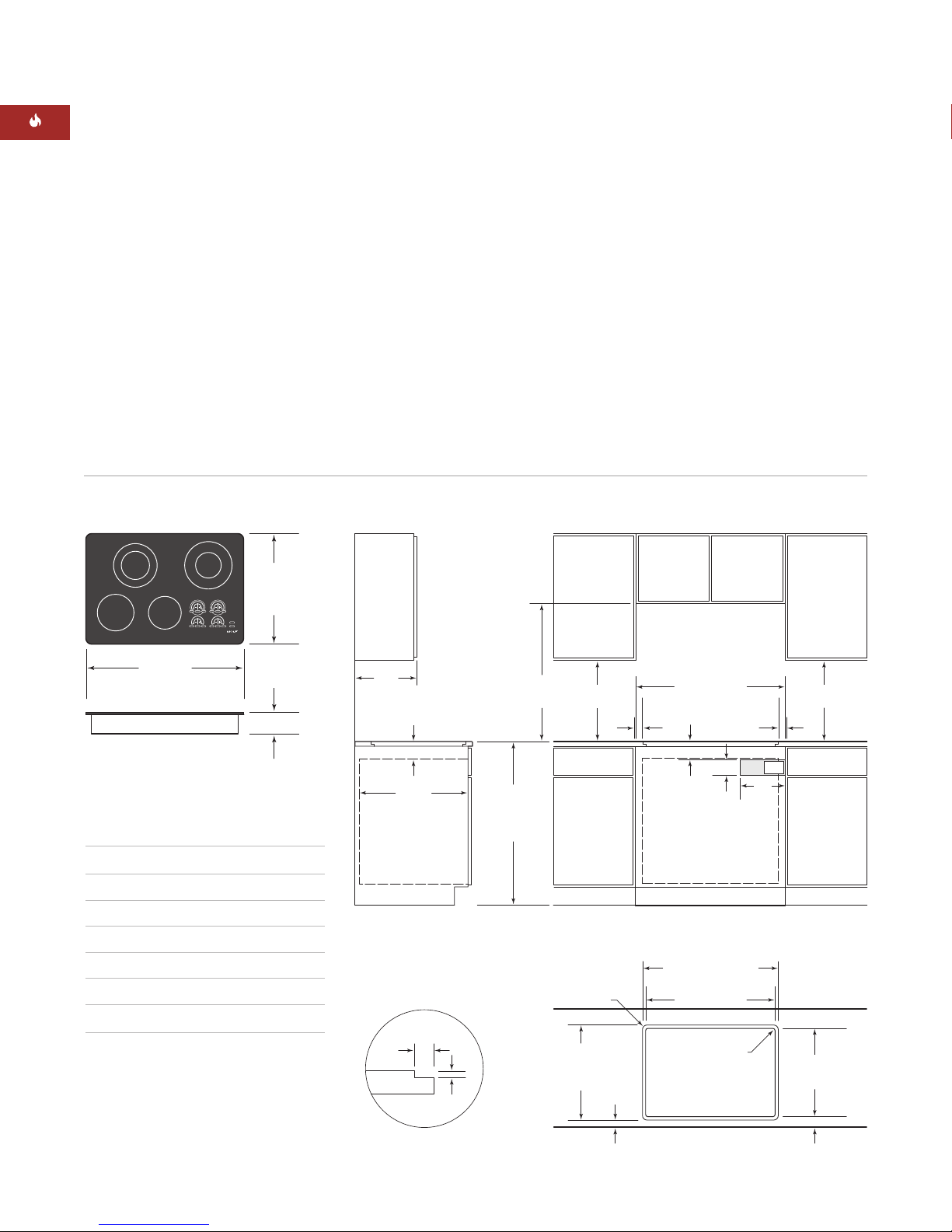
UNFRAMED INSTALLATIONS
MODELS CT30EU AND CT36EU
Unframed electric cooktop Models CT30EU and
CT36EU can be mounted flush with the top of
the countertop or as a frameless installation
with the glass mounted on top of the counter-
top surface.
IMPORTANT NOTE:
The materials required
for a flush mount installation are provided with
the unframed Models CT30EU and CT36EU.
Refer to the instructions provided with the
unframed cooktop installation package (part
#806299) for additional specifications.
FLUSH MOUNT INSTALLATION
There are two options for a flush mount
installation of the unframed electric cooktop;
Option 1 and Option 2.
OPTION 1:
For this flush mount installation, a
recessed area surrounding the standard coun-
tertop cut-out is required. Fabrication of the
recessed area must take place before the final
countertop installation. A template of the coun-
tertop cut-out is provided with the unframed
cooktop for fabrication purposes.
IMPORTANT NOTE:
This fabrication method is
not recommended for molded backsplash style
countertops (triple cove).
For countertop cut-out dimensions, refer to
the Installation Specifications illustration on
page 8 for Model CT30EU and page 9 for
Model CT36EU.
In order to rout the required recessed area for
this flush mount installation, a second
template must be made from 1/2"(13) plywood.
The template will be used as a guide for a top
bearing router bit.
Make the wood template wide enough so that
clamps used to hold this template to the coun-
tertop do not interfere with the router base.
The cut-out dimension of the wood template
should match the outer perimeter of the
template supplied with the cooktop.
Center the wood template over the existing
cut-out in the countertop and clamp. It may be
helpful to use medium-strength double-sided
tape to adherethe template to the countertop;
this will keep the template from shifting during
the routing operation. Make sure that the
adhesive can be easily removed by testing it
on a scrap piece of the countertop. Using a top
bearing router bit with the wood template as a
guide, rout out a 5/16"(8) deep recessed area in
the countertop cut-out.
Flush mount installations are intended
for granite, solid surface or stone coun-
tertop surfaces only. Failure to use high
heat resistant surface will result in coun-
tertop damage if hot cooking utensils are
accidentally moved off the cooking
surface.