WOOD'S POWR-GRIP PFHS69DC User manual

KEEP FOR FUTURE REFERENCE
INSTRUCTIONS
International Version
MODEL NUMBERS: PFHS69DC, PFHL69DC,
PFV69DC, PFHS89DC, PFHL89DC
SERIAL NUMBER: ___________
(please see serial label and record number here)
POWR-FRAME
DC-VOLTAGE
READ ALL INSTRUCTIONS AND WARNINGS
BEFORE OPERATING THIS LIFTER
DESIGNED FOR THE MATERIALS HANDLING PROFESSIONAL
P.O. Box 368 –908 West Main
Laurel, MT USA 59044
phone 800-548-7341
phone 406-628-8231
fax 406-628-8354


Rev 27.3/8-20 1 PF-DC: #35131
TABLE OF CONTENTS
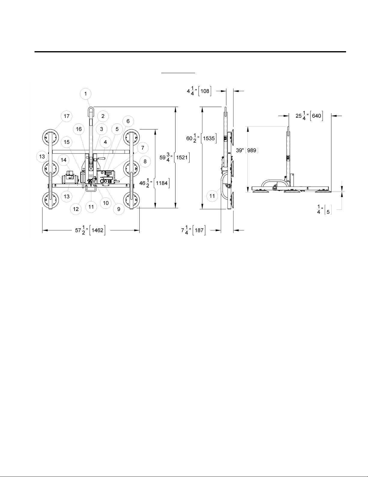
SPECIFICATIONS...........................................................................................................3
WARNINGS....................................................................................................................4
OPERATING FEATURES..................................................................................................5
ASSEMBLY .....................................................................................................................6
INTENDED USE ..............................................................................................................7
LOAD CHARACTERISTICS ...............................................................................................................7
OPERATING ENVIRONMENT ...........................................................................................................8
DISPOSAL OF THE LIFTER ..............................................................................................................8
OPERATION ...................................................................................................................9
BEFORE USING THE LIFTER............................................................................................................9
Taking Safety Precautions..........................................................................................................................9
Performing Inspections and Tests...............................................................................................................9
TO APPLY THE PADS TO A LOAD....................................................................................................10
Positioning the Lifter on the Load ............................................................................................................. 10
Sealing the Pads against the Load ............................................................................................................ 10
Reading the Vacuum Gauge..................................................................................................................... 11
Vacuum Level on Optimal Surfaces........................................................................................................... 11
Vacuum Level on Other Surfaces.............................................................................................................. 11
TO LIFT AND MOVE THE LOAD ......................................................................................................12
Positioning the Lift Bar ............................................................................................................................ 12
Load Capacity and the Warning Light........................................................................................................ 12
Monitoring Vacuum Indicators.................................................................................................................. 12
Monitoring the Low Vacuum Warning Buzzer (if applicable) ........................................................................ 13
Controlling the Lifter and Load ................................................................................................................. 13
In Case of Power Failure.......................................................................................................................... 13
TO ROTATE THE LOAD EDGEWISE .................................................................................................14
TO TILT THE LOAD......................................................................................................................15
TO RELEASE THE PADS FROM THE LOAD .........................................................................................15
AFTER USING THE LIFTER............................................................................................................16
Storing the Lifter..................................................................................................................................... 16
MAINTENANCE ............................................................................................................17
INSPECTION SCHEDULE...............................................................................................................17
Every-Lift Inspection ............................................................................................................................... 17
Frequent Inspection ................................................................................................................................ 17
Periodic Inspection.................................................................................................................................. 17
Infrequent Use ....................................................................................................................................... 18
TESTING SCHEDULE....................................................................................................................18
Operational Tests.................................................................................................................................... 18
Load Test............................................................................................................................................... 18
MAINTENANCE SCHEDULE ...........................................................................................................19

Rev 27.3/8-20 2 PF-DC: #35131
BATTERY TEST .......................................................................................................................... 19
BATTERY RECHARGE .................................................................................................................. 20
BATTERY CHARGER TEST ............................................................................................................ 20
VACUUM PAD MAINTENANCE....................................................................................................... 20
Friction Coefficient .................................................................................................................................. 20
Inspection .............................................................................................................................................. 21
Cleaning................................................................................................................................................. 21
VACUUM TEST ........................................................................................................................... 22
AIR FILTER MAINTENANCE −SMALL ............................................................................................ 23
Filter Function and Conditions Requiring Service ........................................................................................ 23
Filter Service Procedures ......................................................................................................................... 23
VACUUM PUMP MAINTENANCE −DYNAFLO DV1032102 ............................................................... 24
Replacing the Diaphragm......................................................................................................................... 24
Replacing the Head Assembly .................................................................................................................. 24
VACUUM PUMP MAINTENANCE −THOMAS 107CDC20................................................................... 25
Replacing the Diaphragm......................................................................................................................... 25
Replacing the Intake Valve Flapper........................................................................................................... 25
Replacing the Exhaust Valve Flapper and Head Gasket............................................................................... 25
VACUUM SWITCH ADJUSTMENT ................................................................................................... 26
Vacuum Switch Function.......................................................................................................................... 26
Conditions Requiring Readjustment .......................................................................................................... 26
Adjustment Procedure ............................................................................................................................. 27
REPLACEMENT PARTS LIST......................................................................................... 28
LIMITED WARRANTY .................................................................................................. 29

Rev 27.3/8-20 3 PF-DC: #35131
SPECIFICATIONS
Model Number:
8 Vacuum Pads
Vertical Configuration:
―
Horizontal / Small Configuration:
PFHS89DC
Horizontal / Large Configuration:
PFHL89DC
Maximum Pad Spread: (to outer edges)
Vertical Configuration:
―
Horizontal / Small Configuration:
39½" x 47½" [1006 x 1209 mm]
Horizontal / Large Configuration:
39½" x 59½" [1006 x 1514 mm]
Lifter Weight: (for larger configurations)
6 Vacuum Pads
PFV69DC
PFHS69DC
PFHL69DC
57½" x 46½" [1463 x 1184 mm]
37½" x 46½" [955 x 1184 mm]
46½" x 57½" [1184 x 1462 mm]
100 lbs [46kg]
130 lbs [59 kg]
Load Capacity: (rated at 16" Hg [-54 kPa] on clean, smooth, nonporous flat surfaces1)
Per-Pad:
125 lbs [56.5 kg]
125 lbs [57 kg]
Maximum:
700 lbs [320 kg]
1000 lbs [455 kg]
Description:
Designed for use with a crane or other hoisting equipment, PF-9DC lifters employ
vacuum to hold a load for lifting, and they provide manual 180° rotation and manual
90° tilt movements for load manipulation.
Power Source:
12 volts DC, 10 amps (with Thomas pump) or 3.5 amps (with Dynaflo pump)
Battery Capacity:
7 amp-hours
Vacuum Pads:
9" [23 cm] nominal diameter (Model VPFS9), standard rubber, spring-mounted (¼" [7
mm] travel), with #60 filter screen
Rotation Capability:
Manual, 180°, with automatic locking at each ¼ revolution (when desired)
Tilt Capability:
Manual, 90°, with automatic locking in vertical position
Vacuum Pump:
Diaphragm type, 1 SCFM [28 liters/minute] nominal airflow
Vacuum Reserve Tank:
Vacuum reservoir helps prevent immediate vacuum loss in case of power failure and
extends battery life by reducing pump cycles required to maintain vacuum.
Vacuum Gauge:
Dial gauge indicates current vacuum level in positive inches of Hg and negative kPa.
Low Vacuum Warning Light: Red light is energized until vacuum level is sufficient to lift maximum load weight
(higher than 16" Hg [-54 kPa]) and whenever vacuum loss causes pump to re-engage.
Low Vacuum Warning Buzzer (if applicable): Maximum Alarm Volume = 103 dBA at 2' [60 cm]. While lifter is
powered up, audible alarm warns the operator whenever vacuum is not sufficient for
lifting the maximum load weight.
Options:
See separate instructions about optional features.
Operating Elevation:
Maximum = 6,000' [1,828 m]
Operating Temperatures:
32° to 104° F [0° to 40° C]
Service Life:
This lifter is designed to have a service life of 20,000 lifting cycles, when used and
maintained as intended. Vacuum pads, filter elements and other wear-out items are
excluded; see MAINTENANCE and REPLACEMENT PARTS LIST for more information.
For the DISPOSAL OF THE LIFTER after its service life, see INTENDED USE.
ASME Standard BTH-1:
Design Category "B", Service Class "0" (see www.wpg.com for more information)
!!‒CE‒!! Note: This symbol appears in the
INSTRUCTIONS
manual only when requirements of a CE Standard are
different
from requirements of other
standards that also apply to this vacuum lifter. CE requirements are mandatory in geographical areas where CE Standards apply, but may be optional in
other locations.
1Load Capacity is based on a friction coefficient of 1; see MAINTENANCE: VACUUM PAD MAINTENANCE: Friction Coefficient for
additional information.

Rev 27.3/8-20 4 PF-DC: #35131
WARNINGS
Powr-Grip is pleased to offer the most reliable vacuum lifters available.
Despite the high degree of security provided by this product, certain
precautions must be observed to protect the operator and others.
Always
wear personal protective equipment that is appropriate for the material being handled.
Follow trade association guidelines.
Always
operate the lifter under conditions approved for its design (see INTENDED USE:
OPERATING ENVIRONMENT).
Never
operate a lifter that is damaged, malfunctioning, or missing parts.
Never
operate a lifter if the sealing edge of any vacuum pad is cut or otherwise damaged.
Never
remove or obscure warning labels.
Never
operate a lifter if the Maximum Load Capacity or any warning appears to be missing or
obscured.
Always
make certain the contact surfaces of the load and all vacuum pads are clean prior to
attaching the pads (see MAINTENANCE: VACUUM PAD MAINTENANCE).
Never
exceed the Maximum Load Capacity or attempt to lift loads that the lifter is not designed
for (see INTENDED USE: LOAD CHARACTERISTICS).
Never
attempt to lift cracked or broken glass with this lifter.
Always
position the vacuum pads correctly on the load prior to lifting (see OPERATION: TO
ATTACH THE PADS TO A LOAD).
Never
lift a load when any vacuum indicator shows inadequate vacuum.
Never
touch the vacuum release controls during a lift. This may result in loss of vacuum and
release of the load.
Never
allow people to ride on the lifter or the load being lifted.
Never
lift a load higher than necessary or leave suspended loads unattended.
Never
lift a load over people.
Always
keep other personnel far enough away from the lifter to avoid injury in the event of an
unexpected load release.
Always
place the power control in the inactive position and, when possible, disconnect the
power source before opening any enclosure on the lifter. (Only applicable to powered lifters)
Always
remember that modifications to the lifter could compromise its safety. Wood’s Powr-
Grip cannot be responsible for the safety of a lifter that has been modified by others. For
consultation, contact Wood's Powr-Grip (see LIMITED WARRANTY).
Never
disengage both the rotation latch and the tilt latch at the same time.

Rev 27.3/8-20 5 PF-DC: #35131
OPERATING FEATURES
Note: Components featured in the following instructions for assembling, operating or
maintaining the vacuum lifter are underlined on their first appearance in each section.
Standard PFHL69DC shown.
1 LIFT BAIL
7 BATTERY TEST BUTTON
12 VACUUM GAUGE
2 LIFT BAR
8 VALVE HANDLE
13 VACUUM RESERVE TANK
3 PAD FRAME
9 BATTERY GAUGE
14 BATTERY CHARGER
4 TILT RELEASE LEVER
10 AIR FILTER
15 BATTERY
5 LOW VACUUM WARNING LIGHT
11 CONTROL HANDLES
16 ROTATION RELEASE LEVER
6 Enclosure with VACUUM PUMP, VACUUM SWITCH, and LOW VACUUM WARNING
BUZZER (if applicable)
17 VACUUM PAD

Rev 27.3/8-20 6 PF-DC: #35131
ASSEMBLY
1) Open the shipping container and remove all materials for restraining or protecting the vacuum
lifter. Save the container for use whenever lifter is transported.
2) Suspend the lifter from a crane as follows: Select hoisting equipment (crane and hoist, when
applicable) rated to carry the maximum load weight plus the lifter weight (see
SPECIFICATIONS: Maximum Load Capacity and Lifter Weight).
Note: Any application of the lifter must conform to all statutory or regulatory standards that
relate to the hoisting equipment when used in its geographical location (eg, relevant OSHA
standards in the USA).
Tilt the lifter upward on its parking feet (integrated in pad frame) high enough for the lift bar
to move freely, without interference from the shipping container. Swing the lift bar to the
center position of the 180° rotation range, where it latches in position automatically.
WARNING: Hoisting equipment hook must be fitted with restraining latch to
prevent lift bail from slipping off under any circumstances.
Disengage the tilt latch (see OPERATION: TO TILT THE LOAD) and raise the lift bar to a vertical
orientation. Then attach the hoisting equipment hook to the lift bail.
Note: Some hoisting equipment hooks could interfere with an upright load that extends
beyond the lifter's pad frame. If the load would contact the hook during lifter operation, the
operator must prevent this by attaching a sling (or other rigging that does not interfere with
the load) between the hook and the lift bail.
WARNING: Any sling used must be rated to carry maximum load weight plus
lifter weight.
Use the hoisting equipment to raise the lifter out of the shipping container. Be careful to
avoid damaging any vacuum pads. Remove the pad covers and save them for use whenever
the lifter is stored.
3) Connect the electrical connectors uniting the battery to the battery charger and the vacuum
generating system. The lifter is now operational.
4) Perform Operational and Load Tests for the lifter as directed in MAINTENANCE: TESTING
SCHEDULE.

Rev 27.3/8-20 7 PF-DC: #35131
INTENDED USE
LOAD CHARACTERISTICS
WARNING: This lifter is NOT intended for lifting hazardous materials, such as
explosives or radioactive substances.
The operator must verify that the lifter is intended to handle each load, in accordance with the
following requirements:
• The load must not exceed the maximum allowable weight specified under Load Capacity (see
SPECIFICATIONS).
• The load must be a single piece of nonporous or semiporous material with a flat and relatively
smooth contact surface.
2
To determine whether the load is too porous or rough, perform the
test under Vacuum Level on Other Surfaces (see OPERATION: TO ATTACH THE PADS TO A LOAD).
• The load's contact surface must be suitable for obtaining a friction coefficient of 1 with the
lifter's vacuum pads (see MAINTENANCE: VACUUM PAD MAINTENANCE: Friction Coefficient), as
verified by a friction test, or capacity should be derated appropriately. If necessary, contact
Wood's Powr-Grip for help in conducting a friction test.
• In order to avoid damaging the vacuum pads, the load's surface temperature must not exceed
the allowable Operating Temperatures (see SPECIFICATIONS). However, if such an
application cannot be avoided, Wood's Powr-Grip does offer a heat-resistant rubber
compound and other solutions that may enable you to lift loads with higher surface
temperatures. Contact Wood’s Powr-Grip or an authorized dealer for more information.
•While the
minimum
length and width of the load are determined by the Pad Spread (see
SPECIFICATIONS), the
maximum
length and width are determined by the allowable
overhang, or the amount of load material that can extend sideways beyond the vacuum pads
without breaking or otherwise being damaged.
The allowable overhang depends on the kind of load material being lifted, the thickness of the
material, and the angle at which it is handled (if any). Since materials such as glass, stone or
sheet metal each have different physical properties, the allowable overhang must be
evaluated separately for each type of load. If necessary, contact Wood’s Powr-Grip or an
authorized dealer for help in determining the recommended overhang in a specific situation.
• 1" [2.5 cm] is the maximum allowable thickness of loads at the maximum weight (see
SPECIFICATIONS: Maximum Load Capacity). However, allowable thickness increases as load
weight decreases. If necessary, contact Wood’s Powr-Grip for help in determining the
maximum thickness permitted when handling any specific load.
Note: Vacuum pads can stain or deform load surfaces with light colors or soft coatings. The
operator should test such surfaces for detrimental effects before using the lifter on them.
2
Lifters that feature concave vacuum pads can also attach to some kinds of curved loads. Since curvature affects the lifting
capacity, contact WPG for help in determining the Maximum Load Capacity for a particular curved load.

Rev 27.3/8-20 8 PF-DC: #35131
OPERATING ENVIRONMENT
The operator must determine whether the lifter is intended to be used in each work environment,
in accordance with the following restrictions:
WARNING: Never use lifter in dangerous environments.
• This lifter is not intended for use in any environment that is inherently dangerous to the
operator or likely to compromise the lifter's ability to function. Environments containing
explosives, caustic chemicals and other dangerous substances must be avoided when using
the lifter.
• The lifter's work environment is limited by the Operating Elevation and Operating Temperatures
indicated in SPECIFICATIONS.
• The lifter's work environment must be free of metal particles or any other contaminates that
could damage lifter components through airborne contact or any other means of transmission
in the environment. If such contaminates cause a vacuum pump failure, they could result in a
load release and injury to the operator or others nearby.
WARNING: Environmental contaminates could result in vacuum pump failure.
• Using the lifter in wet environments may require the operator to take special precautions:
Moisture on contact surfaces of the load or vacuum pads diminishes the lifter’s slip resistance,
thereby reducing the lifting capacity (see MAINTENANCE: VACUUM PAD MAINTENANCE: Friction
Coefficient).
WARNING: Moisture reduces slip resistance of vacuum pads.
Although the lifter's exterior surfaces can tolerate some exposure to water vapor, they are not
designed to be watertight. Submerging the lifter or using it in rain may damage lifter
components; these and similar conditions must be avoided.
• !!‒CE‒!! If the lifter is employed in a construction area, CE Standard EN 13155 requires the
use of a secondary positive holding device, such as a sling system, designed to support the
load in case of a vacuum system failure.
WARNING: Where CE Standards apply, secondary positive holding device is
required for lifting loads in construction zones.
DISPOSAL OF THE LIFTER
After the vacuum lifter has reached the end of its service life, you must dispose of the lifter in
compliance with all local codes and regulatory standards that are relevant for the geographical
region.
Note: This lifter is equipped with a battery, which may be subject to special disposal
regulations.

Rev 27.3/8-20 9 PF-DC: #35131
OPERATION
BEFORE USING THE LIFTER
The operator must determine whether the lifter is capable of performing each intended task, in
accordance with the SPECIFICATIONS and INTENDED USE sections of this
INSTRUCTIONS
manual. In addition, all of the following preparations must be completed prior to lifting any
load.
Taking Safety Precautions
The operator must be trained in all relevant industry and regulatory standards for the operation
of the vacuum lifter in its geographical location (eg, ASME B30.20 in the USA).
The operator must read and understand this
INSTRUCTIONS
manual, including all
WARNINGS
,
before using the lifter. If necessary, contact Wood’s Powr-Grip or an authorized dealer for
assistance.
WARNING: Always wear appropriate personal protective equipment.
The operator must wear any personal protective equipment and take any other precautions
required to handle the load safely. Consult appropriate trade association guidelines to
determine what precautions are necessary for each type of load material.
Performing Inspections and Tests
WARNING: Always check battery energy before using lifter.
(See MAINTENANCE: BATTERY TEST)
Perform all inspections and tests required by the INSPECTION and TESTING
SCHEDULES (see MAINTENANCE). In addition, if the lifter has been in
storage, always conduct a VACUUM TEST before placing it in service (see
MAINTENANCE).
CAUTION: Examine each air filter regularly, and empty when necessary.
The lifter is equipped with one or more air filters to help protect the vacuum system from
contaminants. In order for a filter to function, the operator must empty the filter bowl before
enough liquid accumulates to contact any portion of the filter element (see MAINTENANCE: AIR
FILTER MAINTENANCE).
If the lifter is equipped with a low vacuum warning buzzer, the volume of the alarm may be
adjusted by rotating the shutter of the warning buzzer. Make sure the alarm is loud enough to
be heard over any other noise that may be present while the lifter is in use. In addition, the
alarm must be clearly audible at the maximum distance the operator may be from the lifter, as
well as through any barriers or obstructions between the operator and the lifter.
WARNING: Make sure alarm is clearly audible over ambient noise at operator
position.

Rev 27.3/8-20 10 PF-DC: #35131
In order to be considered clearly audible,
the alarm volume must exceed ambient noise by
at least 15 dBA at the operator position.
3
Since the Maximum Alarm Volume is 103 dBA,
ambient noise must not exceed 88 dBA under any circumstances. Furthermore, if ambient noise
measures 88 dBA, the alarm volume must be set to maximum and the operator must remain
within 2 ft [60 cm] of the warning buzzer, in order for it to be effective.
TO APPLY THE PADS TO A LOAD
Positioning the Lifter on the Load
Make certain that the contact surfaces of the load and all vacuum pads are free of any
contaminates that could prevent the pads from sealing against the load (see MAINTENANCE:
VACUUM PAD MAINTENANCE).
Center the lifter’s rotation axis to within 2" [5 cm] of the load center, since off-center loading can
cause the load to rotate or tilt unexpectedly (see TO ROTATE THE LOAD EDGEWISE or TO TILT THE LOAD
to follow), and it may also damage the lifter.
4
Make sure that all vacuum pads will fit entirely on
the load’s contact surface (see SPECIFICATIONS: Maximum Pad Spread) and that they will be
loaded evenly while lifting (see SPECIFICATIONS: Per-Pad Load Capacity). Then apply the lifter
to the load so that all pads are touching the contact surface.
Sealing the Pads against the Load
Firm pressure at the center of the lifter
helps the vacuum pads begin to seal
against the load. Pull the valve handle
outward until it latches securely in the
“apply”( ) position (power on), as
shown. This energizes the vacuum
pump, causing air to be drawn at the
pads immediately. The red low vacuum
warning light also turns on and remains illuminated until the lifter attains sufficient vacuum to lift
the maximum load weight (see TO LIFT AND MOVE THE LOAD: Load Capacity and the Warning Light
to follow). The valve handle must remain in the “apply”( ) position throughout the entire
lift.
WARNING: Keep valve handle latched securely in “APPLY” position throughout
lift.
Note: If a vacuum pad has been lying against a hard object (as during shipping), it may be
slightly distorted. Although initially it may be difficult to apply the pad to a load, this condition
should correct itself with continued use.
3
Consult CE Standard EN 457 for alternative ways to determine whether the alarm is clearly audible to operators.
4
The lifter is designed to handle the maximum load weight (see SPECIFICATIONS: Maximum Load Capacity) when the load’s
center of gravity is positioned within 2" [5 cm] of the lifter’s rotation axis. Occasional loading deviations are permissible,
provided that the operator can maintain control of the load at all times and that the load weight is low enough to avoid damaging
the lifter.
TO APPLY

Rev 27.3/8-20 11 PF-DC: #35131
Reading the Vacuum Gauge
The vacuum gauge indicates the current vacuum level in the lifter’s vacuum system. The
green
range indicates vacuum levels sufficient for lifting the maximum load weight, whereas the
red
range indicates vacuum levels that are
not
sufficient for lifting the maximum load weight. The
gauge needle should show a sudden surge in vacuum as the vacuum pads seal against the load.
If it takes more than 5 seconds for the vacuum level to reach 5" Hg [-17 kPa], press on any pad
that has not yet sealed.
Vacuum Level on Optimal Surfaces
When the lifter is attached to clean, smooth, nonporous load surfaces, it should be able to
maintain a vacuum level in the green range on the vacuum gauge, except when used at high
elevations (see SPECIFICATIONS: Operating Elevation). If not, make sure the vacuum switch is
adjusted correctly (see MAINTENANCE: VACUUM SWITCH ADJUSTMENT). If the vacuum switch
cannot be adjusted to maintain a vacuum of 16" Hg [-54 kPa], perform the VACUUM TEST (see
MAINTENANCE) to determine whether there is a deficiency in the vacuum generating system.
Vacuum Level on Other Surfaces
When the lifter is attached to contaminated, rough or porous load surfaces, it may not be able to
maintain a vacuum level in the green range on the vacuum gauge, due to leakage in the seal
between the vacuum pads and the load surface.
5
In the case of contamination, thoroughly
clean the contact surfaces of the load and the vacuum pads (see MAINTENANCE: VACUUM PAD
MAINTENANCE: Cleaning), and reapply the lifter to the load. If the load has rough or porous
surfaces,
the operator must conduct a test to determine whether the lifter is designed
to lift the load
, as follows:
1) Make sure the lifter's vacuum generating system is functioning correctly (see MAINTENANCE:
VACUUM TEST).
2) Apply the vacuum pads to the load as previously directed.
3) After the vacuum pump stops running, disconnect the electrical connector uniting the battery
with the vacuum generating system.
Note: After the test is completed, move the valve handle to the “release”( ) position
(power
off
) before reconnecting the battery.
4) Raise the load a minimal distance, to assure that it is supported by the lifter.
5) Monitor the vacuum gauge while the load is suspended for 5 minutes:
The lifter must
maintain a minimum vacuum level of 10" Hg [-34 kPa] during this time.
If not, the
load does not possess the characteristics required for using this lifter.
6
5
Contaminated loads can also cause the vacuum pump to run frequently or continuously. Since excessive pumping quickly
reduces battery energy, the operator should clean the load when possible, to minimize pumping.
6
Certain load materials are too rough or porous to allow the lifter to form a seal which can be maintained for 5 minutes without
power. However, in geographical locations where CE Standards do not apply, it may be possible to use the lifter to lift such
loads. Contact Wood’s Powr-Grip for more information.

Rev 27.3/8-20 12 PF-DC: #35131
TO LIFT AND MOVE THE LOAD
Positioning the Lift Bar
WARNING: Lift bar must be oriented vertically to lift
load.
Never lift the load from a flat position with the lift bar latched parallel to
the load. Always disengage the tilt latch (see TO TILT THE LOAD to
follow) and raise the lift bar to a vertical orientation before attempting to
lift.
Load Capacity and the Warning Light
A lifter's Load Capacity is rated at a vacuum level of 16" Hg [-54 kPa] (see SPECIFICATIONS).
After the lifter has attained this level, the vacuum pump turns off automatically, to conserve
battery energy. At the same time, the low vacuum warning light turns off, to indicate that the
lifter is ready to lift the maximum load weight.
WARNING: Never attempt to lift load while red warning light is illuminated.
Do not attempt to lift the load while the warning light is illuminated; such an attempt could result
in a load release and possible injury to the operator.
Monitoring Vacuum Indicators
The low vacuum warning light and the vacuum gauge must remain completely visible to the
operator, so that they can be monitored throughout the entire lift.
WARNING: Vacuum indicators must be visible to operator throughout entire
lift.
If the vacuum system experiences leakage while the lifter is attached to the load, the vacuum
pump turns on automatically, as required to maintain sufficient vacuum for lifting the maximum
load weight. The low vacuum warning light also turns on and remains illuminated while the
pump is running, to signal the reduction in vacuum to the operator.
If the pump and warning light turn on while you are lifting a load, make sure the vacuum gauge
shows a vacuum level of 16" Hg [-54 kPa] or higher. If not, move away and stay clear of the
load until it can be lowered to the ground or a stable support.
WARNING: Stay clear of any suspended load while vacuum level is lower than
16" Hg [-54 kPa].
Discontinue lifter use until the cause of the vacuum loss can be determined. If the pump runs
at intervals of ten minutes or less while the lifter is attached to clean, smooth, nonporous
materials, the leakage is likely to be in the vacuum system. In this event, perform the VACUUM
TEST (see MAINTENANCE) and inspect the vacuum pads for damage (see MAINTENANCE: VACUUM
PAD MAINTENANCE: Inspection). If the vacuum loss cannot be remedied immediately, perform
inspection and maintenance as needed to identify and correct any deficiency before resuming
normal operation of the lifter.

Rev 27.3/8-20 13 PF-DC: #35131
Monitoring the Low Vacuum Warning Buzzer (if applicable)
If the lifter is equipped with a low vacuum warning buzzer, an alarm sounds until the lifter attains
sufficient vacuum to lift the maximum load weight (see SPECIFICATIONS: Load Capacity). After
the lifter has attained this vacuum level, the alarm stops sounding, to indicate that the lifter is
ready to lift the load.
WARNING: Never attempt to lift load while alarm is sounding.
Do not attempt to lift the load while the alarm is sounding; such an attempt could result in a load
release and possible injury to the operator.
If the vacuum system experiences leakage while the lifter is attached to the load, the vacuum
pump turns on automatically, as required to maintain sufficient vacuum. The alarm also sounds
while the pump is running, to signal the reduction in vacuum to the operator. If the alarm
sounds while you are lifting a load, make sure the vacuum gauge shows a vacuum level of 16"
Hg [-54 kPa] or higher. If not, immediately move away and stay clear of the load until it can be
lowered to the ground or a stable support.
WARNING: Stay clear of any suspended load while alarm is sounding.
Discontinue lifter use until the cause of the vacuum loss can be determined. Using the lifter on
contaminated, rough or porous surfaces may result in a vacuum loss, due to leakage between
the vacuum pads and the load. Since the alarm may sound in such circumstances, consult the
section TO APPLY THE PADS TO A LOAD: Vacuum Level on Other Surfaces to determine whether the
lifter can be used to lift the load. If the vacuum loss is due to any other cause, perform
inspection and maintenance as needed to identify and correct any deficiency before resuming
normal operation of the lifter.
Controlling the Lifter and Load
When the vacuum indicators show that the lifter is ready, use the hoisting equipment to raise the
lifter and load as needed to clear any obstacles in their path. Use the control handle to keep the
lifter and load in the desired orientation while they are suspended from the crane. Once
sufficient clearance is established, the load can be rotated or tilted as desired (see TO ROTATE THE
LOAD EDGEWISE or TO TILT THE LOAD to follow).
In Case of Power Failure
The lifter is equipped with a vacuum reserve tank, designed to maintain vacuum temporarily in
case of a power failure (ie, in battery).
WARNING: Stay clear of any suspended load in the event of a power failure.
Although the lifter is designed to support the load for at least 5 minutes without power, this
depends on many factors, including the condition of the load and the lifter’s vacuum system (see
INTENDED USE: LOAD CHARACTERISTICS and MAINTENANCE: VACUUM PAD MAINTENANCE,VACUUM
TEST). If a power failure occurs, keep all personnel clear of the suspended load until it can
safely be placed on the ground or a stable support. Correct any deficiency before resuming
normal operation of the lifter.

Rev 27.3/8-20 14 PF-DC: #35131
TO ROTATE THE LOAD EDGEWISE
WARNING: Never disengage both the rotation latch and the tilt latch at the same
time.
This lifter is not designed for rotation and tilt functions to be used at the same time.
Disengaging the rotation and tilt latches simultaneously could cause uncontrolled and
unpredictable load movement, potentially resulting in load damage or injury to the operator.
CAUTION: Rotation function only works when pad frame is latched in vertical
orientation.
Make sure the pad frame is latched in the vertical position of the tilt range (see TO TILT THE LOAD
to follow), as shown in the OPERATING FEATURES illustration, because the rotation function is
not designed to work in any other position.
WARNING: Make sure load is positioned correctly on lifter (see TO APPLY);
unbalanced loads may rotate unexpectedly when latch is
disengaged.
Remember that the load is longer in its diagonal dimensions than in its
side dimensions. Make sure there is sufficient clearance for the load to
rotate without contacting the operator or any nearby objects. Maintain
a firm grip on one control handle to keep the load under control at all
times. Pull the rotation release lever to disengage the rotation latch,
and rotate the load to the desired position. To stop the load’s motion
automatically at each quarter turn, simply let go of the rotation release
lever immediately after initiating the rotation, so that the rotation latch
engages at the next stop. Whenever rotation is not required, keep the
rotation latch engaged, to prevent accidental damage to the load and possible injury to the
operator.

Rev 27.3/8-20 15 PF-DC: #35131
TO TILT THE LOAD
WARNING: Never disengage both the rotation latch and the tilt latch at the same
time.
This lifter is not designed for rotation and tilt functions to be used at the same time.
Disengaging the rotation and tilt latches simultaneously could cause uncontrolled and
unpredictable load movement, potentially resulting in load damage or injury to the operator.
CAUTION: Tilt function only works when pad frame is latched in center position of
rotation range.
Make sure the pad frame is latched in the center position of the rotation range (see TO ROTATE
THE LOAD EDGEWISE preceding), as shown in the OPERATING FEATURES illustration, because the
tilt function is not designed to work in any other position.
WARNING: Make sure load is positioned correctly on lifter (see TO APPLY);
unbalanced loads may tilt unexpectedly when latch is disengaged.
Remember that the load requires more vertical space when tilted
to the upright position, as well as more horizontal space when
tilted to the flat position. Make sure there is sufficient clearance
for the load to tilt without contacting the operator or any nearby
objects. Maintain a firm grip on one control handle to keep the
load under control at all times. If the pad frame is latched in the
vertical position, pull the tilt release lever to disengage the tilt
latch, and prepare for a slight surge of motion as the load begins
to tilt. If load size permits, maintain control with the handle
throughout the tilt. For loads with overhang, it may be
necessary to release the control handle as the load approaches the flat position. If so, keep the
load under control using hand cups or other appropriate means. The pad frame automatically
latches in place when it returns to the vertical position.
TO RELEASE THE PADS FROM THE LOAD
WARNING: Load must be fully supported before releasing vacuum pads.
When the load is at rest and fully
supported, pinch the valve release lever
against the valve handle, to unlatch the
handle. Then push the valve handle
inward to the “RELEASE” position (power
off), as shown. Do not attempt to move
the lifter until the vacuum pads disengage
completely from the load.
TO RELEASE

Rev 27.3/8-20 16 PF-DC: #35131
AFTER USING THE LIFTER
Leave the valve handle in the “RELEASE” position (power off).
CAUTION: Do not set the lifter against any surfaces which could soil or damage the
vacuum pads.
Built-in parking feet can be used to support an unloaded lifter when not suspended from a crane:
Make sure the pad frame is oriented vertically with the parking feet at the bottom. Use the
hoisting equipment to gently lower the lifter until the parking feet support its entire weight.
Make sure the lifter leans securely against an appropriate support; then detach the hoisting
equipment hook from the lift bail.
If the lifter is transported to another location, use the original shipping container and secure the
lifter so as to protect the vacuum pads and all other components from damage while in transit.
Storing the Lifter
Use the covers supplied to keep the vacuum pads clean.
!!‒CE‒!! In accordance with CE Standard EN 13155, the lifter is designed to rest on relatively
horizontal surfaces without tipping over. To store the lifter in this way, set the lifter with the
pads facing downward on a clean, smooth, flat surface. Then lower the lift bar to a horizontal
orientation and place a support under the lift bail.
Charge the battery completely when placing it in storage and at six-month intervals thereafter
(see MAINTENANCE: BATTERY RECHARGE). After charging the battery, disconnect the electrical
connectors uniting the battery to the battery charger and to the vacuum generating system, in
order to minimize power drainage. Preferred temperatures for storing the battery are 32° to
70° Fahrenheit [0° to 21° Celsius]. Higher temperatures require the battery to be charged more
frequently. Storage at temperatures above 100° Fahrenheit [38° Celsius] should be avoided.

Rev 27.3/8-20 17 PF-DC: #35131
MAINTENANCE
WARNING: Always make sure battery is disconnected before servicing lifter.
Note: One or more wiring diagrams are provided in the final section of this
INSTRUCTIONS
manual for reference when servicing the lifter or trouble-shooting a deficiency.
INSPECTION SCHEDULE
Perform inspections routinely, according to the following frequency schedule:
Every-Lift Inspection
• Examine the vacuum pads and load surface for contamination or debris (see VACUUM PAD
MAINTENANCE to follow).
• Examine the vacuum pads, controls and indicators for visual damage (see VACUUM PAD
MAINTENANCE to follow).
• Test the battery for adequate charge (see BATTERY TEST to follow).
If a battery’s charge appears to be inadequate, charge and retest the battery (see BATTERY
RECHARGE to follow). If any other deficiency is detected during the inspection, correct it before
using the lifter and perform the Frequent Inspection to follow.
Frequent Inspection
(
following every 20-40 hours’ use; or whenever lifter is out of service for 1 month or more
)
• Examine the lifter’s structure for visual damage.
• Examine the vacuum system (including vacuum pads, fittings and hoses) for visual damage.
• Examine the air filter for conditions requiring service (see AIR FILTER MAINTENANCE to follow).
• Perform the VACUUM TEST to follow.
• Check for unusual vibrations or noises while operating the lifter.
If any deficiency is detected during the inspection, correct it before using the lifter and perform
the Periodic Inspection to follow.
Periodic Inspection
(
following every 250-500 hours’ use; or whenever lifter is out of service for 1 year or more
)
• Examine the entire lifter for external evidence of looseness, excessive wear, deformation,
cracks, excessive corrosion, dents to structural or functional components, cuts, or any
deficiency which might constitute a hazard.
• Inspect all parts of the electrical system for damage, wear or contamination that could
constitute a hazard, in compliance with all local codes and regulatory standards that are
relevant for the geographical region.

Rev 27.3/8-20 18 PF-DC: #35131
CAUTION: Be sure to use appropriate cleaning methods for each type of electrical
component, as specified by codes and standards. Improper cleaning
can damage components.
• Keep a written record of all Periodic Inspections.
If any deficiency is detected during the inspection, correct it before using the lifter. If
necessary, return the lifter to Powr-Grip or an authorized dealer for repair (see LIMITED
WARRANTY).
Infrequent Use
If a lifter is used less than 1 day in a 2-week period, perform the Periodic Inspection
each time
before using the lifter
.
TESTING SCHEDULE
Perform these tests when placing the lifter in service
initially
and
each time following a repair or
modification
. Correct any deficiency and retest before using the lifter.
Operational Tests
• Perform the VACUUM TEST to follow.
• Test all features and functions of the lifter (see OPERATING FEATURES, OPERATION and
MAINTENANCE).
Load Test
Prove that the lifter can lift 100% of its Maximum Load Capacity (see SPECIFICATIONS), using an
actual load or an equivalent simulation.
7
Employ the following method to test with an actual
load:
1) Place a test load with appropriate LOAD CHARACTERISTICS (see INTENDED USE) on a stable
support. Make sure the load is oriented in the upright position.
8
2) Apply the vacuum pads to the load as previously directed.
3) After the vacuum pump stops running, disconnect the electrical connector uniting the battery
with the vacuum generating system.
Note: After the test is completed, move the valve handle to the “release” ( ) position
(power
off
) before reconnecting the battery.
4) Raise the load a minimal distance, to assure that it is supported by the lifter.
5) Hold the load for 5 minutes. The load must not slip or fall during this time period. If it
does, conduct a VACUUM TEST and inspect each vacuum pad as indicated under VACUUM PAD
MAINTENANCE: Inspection (see sections to follow). Correct any deficiency that is found and
retest the lifter.
7
ASME Standard B30.20 requires the lifter to be tested to 125% of its Maximum Load Capacity.
8
Flat Lifters are exempt from this requirement.
This manual suits for next models
4
Table of contents
Other WOOD'S POWR-GRIP Farm Equipment manuals
Popular Farm Equipment manuals by other brands

Posch
Posch SpaltFix S-415 Multi operating instructions

Highline Manufacturing
Highline Manufacturing Bale Pro Feed Chopper 651 Operator's manual

Krone
Krone Fortima F 1250 Original operating instructions

Berthoud
Berthoud BOXER II-1800 manual

Amazone
Amazone Hektor operating manual

Case IH
Case IH VISION PRO Guide