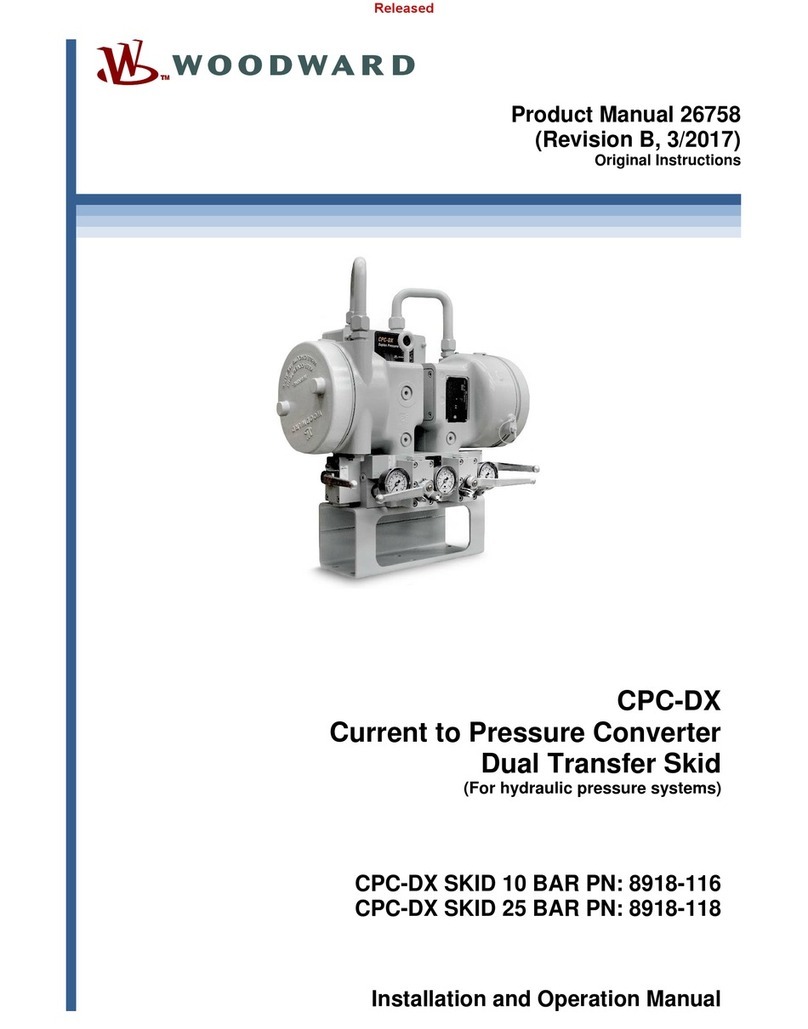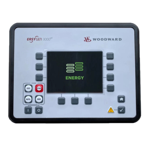
Manual 35162 EPG Governors with Single Phase Droop RoHS Compliant
Woodward 1
Contents
WARNINGS AND NOTICES............................................................................ 3
ELECTROSTATIC DISCHARGE AWARENESS.................................................. 4
CHAPTER 1. GENERAL INFORMATION .......................................................... 5
Application..............................................................................................................5
Part Number Selection ...........................................................................................5
Reference...............................................................................................................6
CHAPTER 2. INSTALLATION,CHECK,AND CALIBRATION............................... 7
General...................................................................................................................7
Speed Control Mounting.........................................................................................7
Actuator Mounting and Linkage..............................................................................7
Install Magnetic Pickup...........................................................................................8
CHAPTER 3. OPERATION........................................................................... 19
CHAPTER 4. DESCRIPTION ........................................................................ 20
Speed Control Applications..................................................................................20
Paralleled Generator Applications........................................................................23
CHAPTER 5. TROUBLESHOOTING............................................................... 24
CHAPTER 6PRODUCT SUPPORT AND SERVICE OPTIONS............................ 25
Product Support Options......................................................................................25
Product Service Options.......................................................................................25
Returning Equipment for Repair...........................................................................26
Replacement Parts...............................................................................................26
Engineering Services............................................................................................27
Contacting Woodward’s Support Organization ....................................................27
Technical Assistance............................................................................................28
REVISION HISTORY ................................................................................... 29
DECLARATIONS......................................................................................... 30

