wtw Cond 315i User manual

ba52300e02 03/2004
Handheld meter
Cond 315i
ba52300e
Operating manual
AR
S/
cm
Tref25
nLF
0
5
2
AR
CAL
M
30
5
°
C
TP
O
Conductivity measuring instrument

Accuracy when
going to press The use of advanced technology and the high quality standard of our
instruments are the result of continuous development. This may result
in differences between this operating manual and your instrument. Al-
so, we cannot guarantee that there are absolutely no errors in this man-
ual. Therefore, we are sure you will understand that we cannot accept
any legal claims resulting from the data, figures or descriptions.
Warranty We guarantee the instrument described for 3 years from the date of
purchase.
The instrument warranty covers manufacturing faults that are discov-
ered within the warranty period. The warranty does not cover compo-
nents that are replaced during maintenance work, e.g. batteries.
The warranty claim extends to restoring the instrument to readiness for
use but not, however, to any further claim for damages. Improper han-
dling or unauthorized opening of the instrument invalidates any warran-
ty claim.
To ascertain the warranty liability, return the instrument and proof of
purchase together with the date of purchase freight paid or prepaid.
Copyright ©Weilheim 2004, WTW GmbH
Reproduction in whole - or even in part - is prohibited without the ex-
press written permission of WTW GmbH, Weilheim.
Printed in Germany.

Cond 315i List of contents
3
Contents
1 Overview . . . . . . . . . . . . . . . . . . . . . . . . . . . . . . . . . . . . . . 5
1.1 SETs of equipment . . . . . . . . . . . . . . . . . . . . . . . . . . . . . . 6
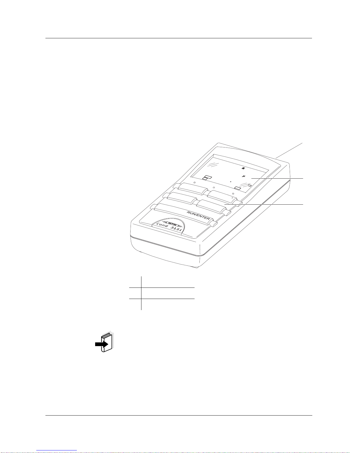
1.2 Keypad . . . . . . . . . . . . . . . . . . . . . . . . . . . . . . . . . . . . . . . 7
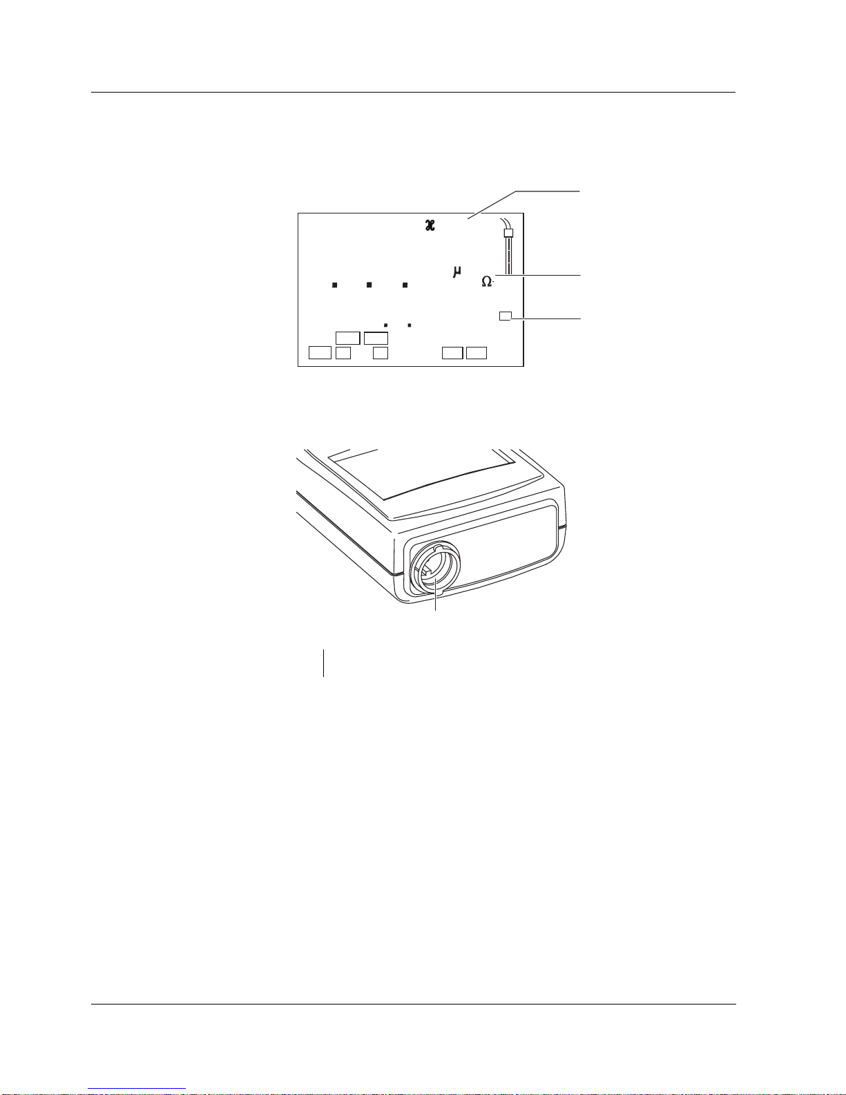
1.3 Display . . . . . . . . . . . . . . . . . . . . . . . . . . . . . . . . . . . . . . . 8
1.4 Jack field . . . . . . . . . . . . . . . . . . . . . . . . . . . . . . . . . . . . . 8
2 Safety . . . . . . . . . . . . . . . . . . . . . . . . . . . . . . . . . . . . . . . .9
2.1 Authorized use . . . . . . . . . . . . . . . . . . . . . . . . . . . . . . . . . 9
2.2 General safety instructions . . . . . . . . . . . . . . . . . . . . . . . 10
3 Commissioning . . . . . . . . . . . . . . . . . . . . . . . . . . . . . . . 11
4 Operation . . . . . . . . . . . . . . . . . . . . . . . . . . . . . . . . . . . . 13
4.1 Switching on the measuring instrument . . . . . . . . . . . . . 13
4.2 Measuring . . . . . . . . . . . . . . . . . . . . . . . . . . . . . . . . . . . 13
4.2.1 General information . . . . . . . . . . . . . . . . . . . . . . 13
4.2.2 Conductivity / Specific resistance . . . . . . . . . . . 14
4.2.3 Salinity . . . . . . . . . . . . . . . . . . . . . . . . . . . . . . . . 15
4.3 Cell constant / Temperature compensation . . . . . . . . . . 17
4.3.1 Setting the cell constant C . . . . . . . . . . . . . . . . 17
4.3.2 Switching the temperature compensation (TC) on/
off 18
4.4 Configuration . . . . . . . . . . . . . . . . . . . . . . . . . . . . . . . . . 21
4.5 Reset . . . . . . . . . . . . . . . . . . . . . . . . . . . . . . . . . . . . . . . 23
5 Maintenance, cleaning, disposal . . . . . . . . . . . . . . . . . 25
5.1 Maintenance . . . . . . . . . . . . . . . . . . . . . . . . . . . . . . . . . . 25
5.2 Cleaning . . . . . . . . . . . . . . . . . . . . . . . . . . . . . . . . . . . . . 26
5.3 Disposal . . . . . . . . . . . . . . . . . . . . . . . . . . . . . . . . . . . . . 26
6 What to do if... . . . . . . . . . . . . . . . . . . . . . . . . . . . . . . . . 27
7 Technical data . . . . . . . . . . . . . . . . . . . . . . . . . . . . . . . . 29
8 Lists . . . . . . . . . . . . . . . . . . . . . . . . . . . . . . . . . . . . . . . . . 33

List of contents Cond 315i
4

Cond 315i Overview
5
1Overview
The compactprecisionCond 315ihandheld meter enablesyou to carry
out conductivity measurements rapidly and reliably.
The Cond 315i handheld meter provides the maximum degree of op-
erating comfort, reliability and measuring certainty for all applications.
The proven procedure for adjusting the cell constant and the special
AutoRead function support you in your work with the conductivity mea-
suring instrument.
Note
If you need further information or application notes, you can obtain the
following material from WTW:
lApplication reports
lPrimers
lSafety datasheets.
You will find information on available literature in the WTW catalog or
via the Internet.
1Keypad
2Display
3Jack field
AR
S/
cm
Tref25
nLF
0
5
2
AR
CAL
M
30
5
°
C
TP
O
1
2
3

Overview Cond 315i
6
1.1 SETs of equipment
The measuring instrument is also available as part of individual SETs
of equipment.
You will find additional information on this and other accessories in the
WTW catalog or via the Internet.
Set (sample configuration):
1 Measuring instrument, Cond 315i
2 Stand
3 – 50 ml control standard for conductivity measuring cells
– Beaker, 50 ml
4 Conductivity measuring cell

Cond 315i Overview
7
1.2 Keypad
Key functions
RUN/ENTER
AR
CAL
M
Select the measuring mode <M>:
–Conductivity/Specific resistance
–Salinity
Switch measuring instrument on/off
<ON/OFF>
–Determine or set up the cell
constant
–Select temperature compensation
<CAL>
Activate/deactivate the AutoRead
function
<AR>
Confirm entries,
start AutoRead
<RUN/ENTER>
M
CAL
AR
RUN/ENTER

Overview Cond 315i
8
1.3 Display
1.4 Jack field
1Conductivity measuring cell
TDS
mg/l
%/K
RCL
Auto
Store
Lin
Time
Baud
Day.Month No.
Ident
Year
S
AutoCal DIN
AutoCalTEC
%
mV/pH
Sal
°
F
mbar
OUpH
8
8.
8
88
8
°
LoBat
Cal
ARng AR
TP
1
m
S/
cm
Sal
cm
1/
C
Tref25 Tref20
nLF
M
cm
Status display
Meas. value display
Function and
temperature display
Sensor symbol
1

Cond 315i Safety
9
2 Safety
This operating manual contains basic instructions that you must follow
during the commissioning, operation and maintenance of the measur-
ing instrument. Consequently, all responsible personnel must read this
operating manual carefully before working with the measuring system.
Theoperatingmanualmustalwaysbeavailablewithinthevicinityofthe
measuring system.
Target group The measuring instrument was developed for work in the field and in
the laboratory.
We assume that, as a result of their professional training and experi-
ence, the operators will know the necessary safety precautions to take
when handling chemicals.
Symbols
used
Warning
indicates instructions that must be followed to prevent damage to your
instrument.
Note
indicates notes that draw your attention to special features.
Note
indicates cross-references to other documents, e.g. application re-
ports, operating manuals of probes, etc.
2.1 Authorized use
The authorized use ofthe measuring instrument consists exclusively of
the measurement of the conductivity and salinity in the field and labo-
ratory.
Thetechnicalspecificationsasgivenin chapter7 TECHNICAL DATA must
be observed. Only the operation and running of the measuring instru-
ment according to the instructions given in this operating manual is au-
thorized.
Any other use is considered to be unauthorized.

Safety Cond 315i
10
2.2 General safety instructions
This instrument is built and inspected according to the relevant guide-
lines and norms for electronic measuring instruments (see chapter 7
TECHNICAL DATA).
It left the factory in a safe and secure technical condition.
Function and operating
safety The smooth functioning and operational safety of the measuring instru-
ment can only be guaranteed if the generally applicable safety mea-
sures and the specific safety instructions in this operating manual are
followed during operation.
The smooth functioning and operational safety of the measuring instru-
ment can only be guaranteed under the environmental conditions that
are in specified in chapter 7 TECHNICAL DATA.
If the instrument was transported from a cold environment to a warm
environment, the formation of condensate can lead to the faulty func-
tioning of the instrument. In this event, wait until the temperature of the
instrument reaches room temperature before putting the instrument
back into operation.
Safe operation If safeoperationisnolongerpossible,theinstrumentmust betakenout
of service and secured against inadvertent operation!
Safe operation is no longer possible if the measuring instrument:
lhas been damaged in transport
lhas been stored under adverse conditions for a lengthy period of
time
lis visibly damaged
lno longer operates as described in this manual.
If you are in any doubt, please contact the supplier of the instrument.
Obligations of
the purchaser The purchaser of the measuring instrument must ensure that the fol-
lowing laws and guidelines are observed when using dangerous sub-
stances:
lEEC directives for protective labor legislation
lNational protective labor legislation
lSafety regulations
lSafety datasheets of the chemical manufacturers.

Cond 315i Commissioning
11
3 Commissioning
Scope of delivery lHandheld meter, Cond 315i
lOperating manual and short operating manual
l4 batteries, 1.5 V Mignon type AA (in the instrument)
For details of scope of delivery of SETs, see chapter 1.1 SETSOF
EQUIPMENT and WTW catalog.

Commissioning Cond 315i
12

Cond 315i Operation
13
4 Operation
4.1 Switching on the measuring instrument
4.2 Measuring
4.2.1 General information
Preparatory activities Perform the following preparatory activities when you want to measure:
Temperature probe Only carry out measurements with a temperature probe. The tempera-
ture probe is shown on the display by TP.
The WTW TetraCon325 conductivity measuring cell has a temperature
sensor integrated in it.
Note
The conductivity measuring instrument automatically recognizes the
type of the temperature probe used. This enables the measuring cells
to be connected with the NTC30 or Pt1000.
Temperature
compensation The instrument has a nonlinear temperature compensation that can be
switched off (see section 4.3 CELL CONSTANT / TEMPERATURE COMPEN-
SATION).
Reference temperature,
Tref The reference temperature (Tref) can be switched between 20 °C and
25 °C. It appears on the display as Tref20 or Tref25.To switch over the
reference temperature, see section 4.4 CONFIGURATION.
1Connect a conductivity measuring cell to the measuring instru-
ment.
2 Press the <ON/OFF> key.
Display test appears briefly on the display. Subsequently, the
selectedcellconstantsandthetemperaturecompensationthat
was set up appear for approx. one second one after the other.
The measuring instrument then switches to the measuring
mode that was last selected.
1Connect a conductivity measuring cell to the measuring instru-
ment.
2 Set up the correct cell constant for the conductivity measuring
cell (see section 4.3.1).
3Use <M> to change between the conductivity measuring mode
(in
µS/cm) or salinity (SAL).

Operation Cond 315i
14
4.2.2 Conductivity / Specific resistance
Note
You can display measured values in the units µS/cm (conductivity) or
MΩcm (specific resistance). This basic setting is described in section
4.4 CONFIGURATION.
Thus, you can carry out conductivity measurements or measurements
of the specific resistance:
Conductivity µS/cm
Specific resistance
MΩ⋅cm
1Perform the preparatory activities according to section 4.2.1.
2 Immerse the conductivity measuring cell in the test sample.
3Press the <M> key until appears on the status display. De-
pending on the basic setting in the CONFIGURATION menu, one
of the following display indicators appears on the display:
AR
8
1
cm
1/ /
K
%
°
F
ARng RCL
Cal
Lin
Tref20
LoBat
M
m
Sal
TDS
S
Auto
Store
Sal
mbar
%
mg/l
OUpH
mV/pH
cm
AutoCal DIN
AutoCalTEC
Time
Baud
Day.Month No.
Ident
Year
0
5
2
30
5
°
TP
S/
cm
C
Tref25
nLF
4Wait for a stable measured value.
m
%
mg/l
S/
cm
S
AR
8
cm
1/ /
K
%
°
F
ARng RCL
Cal
Lin
Tref20
LoBat
Sal
TDS
Auto
Store
Sal
mbar
OUpH
mV/pH
AutoCal DIN
AutoCalTEC
Time
Baud
Day.Month No.
Ident
Year
0
5
2
86
8
°
TP
C
Tref25
nLF
1
M
cm

Cond 315i Operation
15
4.2.3 Salinity
You can carry out the salinity measurements as follows:
AutoRead AR
(Drift control) The AutoRead function (drift control) checks the stability of the mea-
surement signal. The stability has a considerable effect on the repro-
ducibility of the measured value.
1Perform the preparatory activities according to section 4.2.1.
2 Immerse the conductivity measuring cell in the test sample.
3Press the <M> key until Sal appears on the status display. The
salinity value appears on the display.
4Wait for a stable measured value.
Tref25
/
K
cm
1/
°
F
%
8
mg/l
1
RCL
ARng AR
LoBat
Cal
Tref20
Lin
m
S/
cm
M
TDS
S
Auto
Store
Sal
mbar
%
OUpH
mV/pH
cm
AutoCal DIN
AutoCalTEC
Time
Baud
Day.Month No.
Ident
Year
2
1
2
23
3
°
TP
Sal
C
nLF
1Select the required measuring mode with <M>.
2 Activate the AutoRead function with <AR>.
The current measured value is frozen (hold function).
3Start AutoRead with <RUN/ENTER>.
AR flashes until a stable measured value is reached.
8
1
cm
1/ /K
%
°
F
ARng RCL
Cal
Lin
Tref20
LoBat
M
m
Sal
TDS
S
Auto
Store
Sal
mbar
%
mg/l
OUpH
mV/pH
cm
AutoCal DIN
AutoCalTEC
Time
Baud
Day.Month No.
Ident
Year
0
5
2
30
5
°
AR
TP
S/cm
C
Tref25
nLF

Operation Cond 315i
16
Note
The current AutoRead measurement can be terminated at any time
(accepting the current value) by pressing <RUN/ENTER>.
4If necessary, start the next AutoRead measurement with
<RUN/ENTER>.
5 To terminate AutoRead: Press the <AR> key.

Cond 315i Operation
17
4.3 Cell constant / Temperature compensation
You can adjust the cell constant and switch the temperature compen-
sation on/off.
4.3.1 Setting the cell constant C
The cell constant of the conductivity measuring cell can be set to one
of the following values:
l0.475 cm-1
l0.100 cm-1
l0.875 cm-1
Note
Thecellconstanttobeselectedmusteitherbetakenfrom theoperating
manual of the measuring cell or is printed on the measuring cell.
Setting
the cell constant You can select a cell constant from the fixed values
0.475 cm-1, 0.1 cm-1, 0.875 cm-1 :
1Press the <CAL> key repeatedly until the status display
CELL appears.
2Press the <RUN/ENTER> key.
3 Press the <CAL> key repeatedly until the required cell con-
stant, e.g. 0.475 cm-1, appears on the display.
OUpH
F
L
Store
RCL
AR
Auto
AutoCal DIN
AutoCalTEC
LoBat
Cal
ARng
Tref25 Tref20
Lin
nLF
Sal
%
mg/l
mV/pH
cm
°
°
TP
m
S/
cm
cm
1/
FC
%/
K
M
TDS
Sal
8
1
S
mbar
Time
Baud
Day.Month No.
Ident
Year
L
CL
E
Cal
L
S
A
C
1
LoBat
Lin
nLF
Tref20
RCL
AR
°
°
TP
FC
%/
K
M
%
mg/l
mV/pH
m
S/
cm
Sal
TDS
Auto
Store
Sal
mbar
OUpH
cm
AutoCal DIN
AutoCalTEC
Time
Baud
Day.Month No.
Ident
Year
5
07
4
cm
1/
Tref25
ARng

Operation Cond 315i
18
4.3.2 Switching the temperature compensation (TC) on/off
The basis for calculating the temperature compensation is the selected
reference temperature, Tref 25 or Tref 20. For details of how to select
the reference temperature, see section 4.4 CONFIGURATION.
You can select from the following settings:
lNonlinear temperature compensation (nLF) according to EN 27
888
l
ll
lNo temperature compensation (- - - -)
Note
ips Select the temperature compensations given in the following table ac-
cording to the respective test sample:
Application tips
4To return to the measuring mode: Press the <M> key.
Sample Temperature compensation Display in-
dicator
Natural water (ground
water, surface water
and drinking water)
nLF
according to DIN 38404
EN 27 888
Ultrapure water nLF
according to DIN 38404
EN 27 888
Other aqueous solu-
tions Measure without temperature
compensation - - - -
Salinity
(seawater) Automatic nLF according to
IOT Sal,

Cond 315i Operation
19
Switching on the
nonlinear temperature
compensation
You can switch on the nonlinear temperature compensation as follows:
1Press the <CAL> key repeatedly until the status display tc
appears on the display.
2Press the <RUN/ENTER> key.
3 Press the <CAL> key repeatedly until nLF appears on the dis-
play.
4To return to the measuring mode: Press the <M> key.
O Sal
LF
Tref25 Tref20
AutoCalTEC
RCL
LoBat
Cal
ARng AR
Lin
nLF
Store
Sal
°
°
TP
cm
1/
FC
%/
K
88
8
1
S/
cm
m
M
TDS
S
Auto
mbar
%
mg/l
UpH
mV/pH
cm
AutoCal DIN
Time
Baud
Day.Month No.
Ident
Year
c
t
S
m
cm
M
mbar
%
mg/l
mV/pH
8
Sal
°
°
TP
cm
1/
FC
%/
K
RCL
AR
LoBat
Cal
Tref20
Lin
Sal
TDS
Auto
Store
OUpH
AutoCal DIN
AutoCalTEC
Time
Baud
Day.Month No.
Ident
Year
F
L
n
ARng
Tref25
nLF
3
1
4
S/
cm
1

Operation Cond 315i
20
Switching the tempera-
ture compensation off You can switch off the temperature compensation as follows:
1Press the <CAL> key repeatedly until tc appears on the dis-
play.
2Press the <RUN/ENTER> key.
3 Pressthe <CAL> key repeatedly until4 dashes appears onthe
display.
4The temperature compensation is switched off.
5 To return to the measuring mode: Press the <M> key.
O Sal
LF
Tref25 Tref20
AutoCalTEC
RCL
LoBat
Cal
ARng AR
Lin
nLF
Store
Sal
°
°
TP
cm
1/
FC
%/
K
88
8
1
S/
cm
m
M
TDS
S
Auto
mbar
%
mg/l
UpH
mV/pH
cm
AutoCal DIN
Time
Baud
Day.Month No.
Ident
Year
c
t
S
m
cm
M
mbar
%
mg/l
Tref25
nLF
Cal
Lin
Sal
°
°
TP
cm
1/
FC
%/
K
RCL
AR
LoBat
Tref20
Sal
TDS
Auto
Store
OUpH
mV/pH
AutoCal DIN
AutoCalTEC
Time
Baud
Day.Month No.
Ident
Year
-
-
-
ARng
-
3
11
S/
cm
4
Other manuals for Cond 315i
1
Table of contents
Other wtw Measuring Instrument manuals

wtw
wtw SenTix 950 User manual

wtw
wtw Cond 315i User manual

wtw
wtw OxiTop IS 6 User manual

wtw
wtw pH 3150i User manual

wtw
wtw Cond 7310 User manual

wtw
wtw Turb 2000 Series User manual

wtw
wtw Oxi 3310 IDS User manual

wtw
wtw inoLab Oxi Level 2 User manual

wtw
wtw SenTix FET-D User manual

wtw
wtw inoLab Cond 730 User manual