wurth SWS 180/230 Power User manual

Bedienungsanleitung
Operating Instructions
Notice d’utilisation
Instrucciones para el manejo
Instruções de utilização
Istruzioni d‘uso
Gebruiksaanwijzing
Betjeningsvejledning
Bruksanvisning
Bruksanvisning
Käyttöohje
√‰ËÁ›Â˜ ¯ÂÈÚÈÛÌÔ‡
Kullanım kılavuzu
Winkelschleifer SWS 180/230 Power
Angle Grinder SWS 180/230 Power
Meuleuse angulaire SWS 180/230 Power
Amaoladora SWS 180/230 Power
Rebarbadora SWS 180/230 Power
Smerigliatrice angolare SWS 180/230 Power
Haakse slijpmachine SWS 180/230 Power
Vinkelsliber SWS 180/230 Power
Vinkelslib SWS 180/230 Power
Vinkelsliber SWS 180/230 Power
Kulmahiomakone SWS 180/230 Power
°ˆÓÈ·Îfi˜ ÏÂÈ·ÓÙ‹Ú·˜ SWS 180/230 Power
Taµlama makinesi SWS 180/230 Power

1
2
9 8 7 6
3
1
9
7
1
10
8
4
5

8
Tool Specifications
Angle Grinder SWS 180 Power SWS 230 Power
Article number 702 496 X 702 498 X
Input power 2 500 W 2 500 W
Output power 1 700 W 1 700 W
No-load speed 8 500 RPM 6 600 RPM
Grinding disc dia. max. 180 mm max. 230 mm
Grinding disc thickness min. 1 mm, max. 10 mm min. 1 mm, max. 8 mm
Mounting hole 22.2 mm 22.2 mm
Weight approx. 5.4 kg approx. 5.4 kg
Safety class / II / II
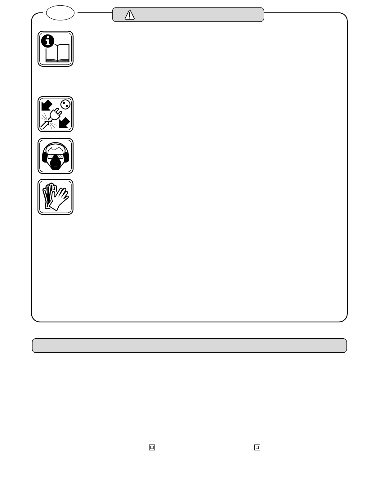
Working safely with this machine is
possible only when the operating
and safety information are read
completely and the instructions con-
tained therein are strictly followed.
In addition, the general safety in-
structions in the enclosed booklet
must be followed.
If the cable is damaged or cut through
while working, do not touch the cable
but immediately pull the mains plug.
Never use the machine with a dam-
aged cable.
Wear protective goggles, ear protec-
tors and face mask.
Wear protective gloves and sturdy
shoes. When necessary, also wear an
apron.
When working with the machine, al-
ways hold it firmly with both hands
and provide for a secure stance.
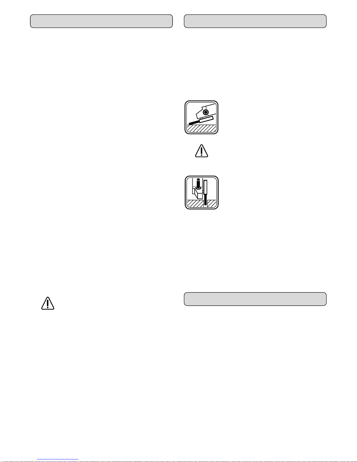
❑For all work with the machine, the auxiliary han-
dle 6 and the protective guard 7 must be mounted.
❑Use only grinding tools whose allowable speed is
at least as high as the no-load speed of the ma-
chine.
❑Observe the dimensions for the grinding disc. The
mounting hole diameter must fit the centring flange
(square form part). Do not use reducer pieces or
adapters.
❑Check grinding tools before use. The grinding tool
must be properly mounted and turn freely. Perform
a test run for at least 30 seconds without load. Do
not use damaged, out of round or vibrating grind-
ing tools.
❑Do not clamp the machine in a vice.
❑Always direct the cable to the rear away from the
machine.
❑Clamp the workpiece in case it does not remain
stationary from its own weight.
❑When grinding metal, flying sparks are produced.
Take care that no persons are endangered. Be-
cause of the danger of fire, no combustible mate-
rials should be located in the vicinity (spark flight
zone).
❑Apply the machine to the workpiece only when
switched on.
❑Always switch off the machine and allow to come
to a stop before putting down.
❑Keep hands away from rotating grinding tools.
❑Connect machines that are used in the open via a
residual current circuit breaker with a triggering
current of 30 mA maximum. Use only extension
cables that are intended for outdoor use and are
protected against splash water.
❑For the labelling of the machine, do not drill into
the housing or attach with rivets. The protective in-
sulation is then no longer ensured. Use stickers.
❑Use only original WÜRTH parts and accessories.
For your safety
GB
☞ For further notes on safety refer to enclosed Sheet

9
1Clamping lever
2Switch-on lock
3On/Off switch
4Release button
5Ventilation slots
6Auxiliary handle
7Protective guard
8Grinding disc
9Latching lever for the protective guard
10 Clamping unit for the cutting/roughing disc
Not all of the accessories illustrated or described are included
as standard delivery.
The machine is intended for the grinding and cutting of
metal and stone materials without the use of water.
For the cutting of stone, a guide sled (optional extra) is
prescribed.
Mounting the Protective Devices
❑Before any work on the machine itself, pull the
mains plug.
Protective Guard 7
The protective guard 7 remains mounted on the ma-
chine for all work.
Before putting into operation for the first time, mount the
protective guard. For this purpose, insert the nose of the
protective guard into the groove of the machine and
turn the protective guard.
To adjust the protective guard, loosen the locking le-
ver 9and rotate the protective guard 7to the required
position (working position) (Figure A). Select only posi-
tions in which the protective guard latches. The closed
side of the protective guard 7 must always point to the
operator.
Auxiliary Handle 6
The machine may be operated only with the auxiliary
handle 6 mounted. Firmly screw in the auxiliary han-
dle 6 on the right or left of the machine head depending
on the working to be performed (Fig. D).
Rotating the Machine Handle
The machine handle can be rotated with respect to the
machine housing in 90° steps.
In this manner, the on/off switch can be brought into a
favourable handling position for special working situa-
tions, for example, for cut-off work with the guide sled
(optional accessory) and for left-handed persons.
For this purpose, press the unlocking button 4and rotate
the machine handle to the desired position until the ma-
chine handle distinctly latches. The machine handle can
berotatedtothe rightby 90°,to theleft by90° and180°.
Mounting the Grinding Tools (Accessory)
The allowable speed [RPM] or circumferential
speed [m/s] of the grinding wheels used must at least
conform to those given in the table. Therefore, always
pay attention to the allowable RPM/circumferential
speed on the label of the grinding wheel.
Roughing/Cutting Disc
Pull the clamping lever 1 from the latched position and
swing completely forwards to the stop (Fig. B).
Turn over the machine and unscrew the clamping
unit 10 counter clockwise by hand out of the drive spin-
dle (Fig. C).
Place the grinding tool on the drive spindle. Take care
that it us correctly centred.
Screw the clamping unit 10 clockwise (to the right) into
the drive spindle until one or two detent points can be
felt. Do not use tools!
Swing the clamping lever 1 back to its initial position
and latch.
Elastic Grinding Plate (Accessory)
Place the elastic grinding plate together with the sand-
ing sheet on the drive spindle.
Screw the special clamping unit (Accessory) in the
clockwise direction (to the right) into the drive spindle
until one or two detent points can be felt. Do not use
tools!
Unscrewing of the clamping unit takes place by hand in
the counter clockwise direction (to the left). Do not use
tools.
Operating controls
Use as intended
Before Use
D
max.
[mm]
b
max.
[mm]
d
[mm] [RPM] [m/s]
180
230 10
822.2 8 500
6 600 80
180
230 ––
8 500
6 600 80
b
d
D
,,,,,,
,,,,,,
,,,,,,
,,,,,,
D

10
Always use the correct supply voltage: The power sup-
ply voltage must match the information quoted on the
tool identification plate. Tools with a rating of 230 V
can also be connected to a 220 V supply.
Switching On/Off
Switching on: Press the switch-on lock 2and the
on/off switch 3at the same time.
Locking: Leave the switch-on lock 2pressed and
release the on/off switch 3.
Switching off: Press the on/off switch 3and release.
Switch configuration without locking
(Dead-man switch, specific countries)
Switching on: Press the on/off switch 3.
Switching off: Release the on/off switch 3.
Note: The on/off switch 3 can be actuated only when
the clamping lever 1 in the machine head is latched (in-
itial position).
Soft Start
As a result of soft starting of the machine, a 16-A fuse
in the power circuit is adequate.
Restarting Protection
This function prevents uncontrolled restarting after a
power failure or when the mains plug was pulled. To put
back into operation, switch off with the on/off switch 3
and back on again.
Motor Brake
The grinding tool is braked to a stop in a few seconds
when switched off.
When the mains fail or the mains plug
is pulled, the machine runs on without
being braked. The grinding tool is
braked when the machine is switched
off.
❑Clamp the workpiece in case it does not remain sta-
tionary from its own weight.
❑Do not load the machine so heavily that it comes to
a standstill.
❏Roughing and cutting discs become very hot while
working; do not touch before they have cooled.
Grinding The best result are achieved with an an-
gle of 20° to 40° for grinding. Move the
machine back and forth with light pres-
sure. In this manner, the workpiece does
not become too hot, no discoloration oc-
curs and no ridges are produced.
Under no circumstances should a cut-
ting disk be used for roughing work.
Cutting When cutting, do not press, tilt or oscil-
late. Work with a moderate feed rate
that is suited to the material to be
worked.
The direction in which one cuts is important. The ma-
chine must always rotate opposite to the direction of
motion (Fig. E); therefore never move the machine in the
other direction! Otherwise, the danger exists that it will
be forced uncontrolled out of the cut.
Storage
To protect against damage and dirt, screw in the clamp-
ing unit and latch the quick clamping lever.
❑Before any work on the machine itself, pull the
mains plug.
Always keep the machine and the ventilation slots
clean. Blow out the motor regularly with dry com-
pressed air.
If the machine should happen to fail despite the care
taken in manufacture and testing, repair should be car-
ried out by an authorised customer services agent for
Würth power tools.
For inquiries and replacement parts orders, always in-
clude the article number from the nameplate of the ma-
chine.
Initial Operation Operating Instructions
Maintenance and Cleaning

11
Recycle raw materials instead of dis-
posing as waste.
Machine, accessories and packaging
should be sorted for environment-friend-
ly recycling.
The plastic components are labelled for categorized re-
cycling.
For this Würth machine, we provide a 12 -month guar-
antee against material and workmanship defects from
the date of purchase (verified by invoice or delivery
document). Damage that has occurred will be corrected
by replacement or repair.
Damage caused by normal wear, overloading or im-
proper handling is excluded from the guarantee.
Claims can be recognised only when the machine is
presented undisassembled to a Würth branch office or
a Würth field service employee.
Measured values determined according to EN 50 144.
The A-weighted noise levels of the tool are typically:
Sound pressure level: 86 dB (A). Sound power level:
99 dB (A).
Wear ear protectors!
The weighted acceleration is typically 6.0 m/s2.
We declare under our sole responsibility that this prod-
uct is in conformity with the following standards or
standardization documents: EN 50 144, EN 55 014,
EN 61 000-3-2, EN 61 000-3-3 according to the pro-
visions of the regulations 98/37/EC, 89/336/EEC,
73/23/EEC.
98
Adolf Würth GmbH & Co. KG
ppa. Otto Steck Karl Weidner
Environmental Protection
Guarantee
Noise/vibration information
Declaration of conformity
Subject to change without notice
Table of contents
Other wurth Grinder manuals