manuals.online logo
Brands
  1. Home
  2. •
  3. Brands
  4. •
  5. Wyrestorm
  6. •
  7. Extender
  8. •
  9. Wyrestorm EX-1UTP-IR-50-POH User manual

Wyrestorm EX-1UTP-IR-50-POH User manual

Place the IR TX transmitter eye directly over the infrared receiving area
of the source device (.i.e. Blu-Ray, cable/satellite box etc.), and secure
with the adhesive backing. Location of the transmitter eye on the source
device may need to be adjusted later to achieve best IR performance.
NOTE: Infrared windows can be seen by shining a flashlight onto
the front of the device – the IR sensor will appear as a small,
round diode behind the fascia.
Connect the IR TX 3.5mm jack to the IR TX port on the EX-1UTP-IR-50-
POH TRANSMITTER. For bidirectional control of source and display from
either location, connect an IR link cable between the IR RX port and your
control system.
A control system can be connected using an IR link cable to pass
remote control commands between source and display via the extender.
Connect the stereo end of the IR link cable to the IR RX port of the
TRANSMITTER and the mono end to the to the control system used.
Alternatively, control of the display from the source location can be
achieved by placing the IR RX receiving eye in clear line of sight with the
remote handset used to control. Adjustment of the IR RX eye may be
required later to achieve the best performance.
NOTE: An infrared signal can be passed from TRANSMITTER
location to display RECEIVER e.g. a control system transmitting a
“TV off” command.
Connect the IR RX 3.5mm jack to the IR RX port on the EX-1UTP-IR-50-
POH RECEIVER. For bidirectional control, connect an IR TX transmitter
eye from IR TX port of the RECEIVER.
Place the IR TX eye directly over the infrared receiving area of the display,
securing with the adhesive backing. Location of the eye on the display
device may need to be adjusted later to achieve best IR performance.
We strongly recommend using supplied mounting brackets to
secure TRANSMITTER & RECEIVER baluns. Sudden movement of
these devices could lead to loss of picture/sound if connections
become loose or strained, resulting in unnecessary service call-
backs.
Connect the TRANSMITTER & RECEIVER baluns with a good quality, well
terminated and tested Cat5e/6/7 cable with RJ45 connectors wired to
the 568B standard at both ends.
Ensure all connectors are pushed securely to each port and supported
by the connector strain relief clip to prevent them from becoming loose.
The quality of cable and RJ45 termination is essential for
successful distribution of video, audio, control and power from
TRANSMITTER to RECEIVER. Poor cable and terminations lead to
intermittent performance and longer install times.
Finally, add the provided 12v power supply to the TRANSMITTER. The
PoH function carries power along the length of the cable to power the
display RECEIVER so no additional power is required at the display
location. Illuminated LINK lights on TRANSMITTER and RECEIVER will
indicate a successful connection.
1
2
3
4
5
6
!
!
Single Cable HD Extenders with bidirectional IR and PoH
Part Number EX-1UTP-IR-50-POH
Cat5e Wiring Guide
The quality of termination for every RJ45
is essential. Poor terminations leads to
intermittent performance and longer install
times.
SOURCE DEVICE
DISPLAY OUTPUT
12v power
hdmi
hdmi
cat 5e/6 cable up to 50m (164ft)
ir tx cable ir tx cable
COntrol
System
ir rx cable
ir rx
ir link cable
1
3
2
4
6
4
5
NOTE: Although WyreStorm
products are tested with Cat5e,
we recommend Cat6 due
to increased bandwidth and
improved capacity for handling
large transmissions and power
along a single cable.
TRANSMITTER
RECEIVER Optional 5v power
available should
power transmission
issues be
encountered from
TRANSMITTER
location.
Extending HDMI using Cat5e/6 to 50m/164ft
WyreStorm Quickstart Guide
Cat5e/6 Cable Performance Guide EX-1UTP-IR-50-POH
0ft 328ft32ft 65ft 98ft 131ft 164ft 197ft 230ft 262ft 295ft
0m 100m10m 20m 30m 40m 50m 60m 70m 80m 90m
Troubleshooting
Regardless of manufacturer or product, the majority of installation
difculties can typically be attributed to communication problems
between devices or when high bandwidth transmissions are attempted
with insufcient cable/connections. Should you nd yourself in such a
situation, we have drawn up the following checklist of general issues
and causes that should help you shoot your way out of trouble without
seeking further assistance.
No or poor quality picture?
Device Connection - Are you connected and powered? Double check
all HDMI, UTP and 12v power connections are rmly inserted into correct
ports and that all devices are powered. In the event of a poor quality or
excessive cable run, the 5v DC input of the RECEIVER may have to be
used.
Cable length – is your signal struggling to transmit signals or power
the distance of your cable? If you are approaching the maximum capacity
of your transmission cable distance, try changing to long cable mode on
the DIP switch.
Signal strength – the use of cable joins, stranded patch panels, wall
outlets and stranded patch leads as interconnects between them, can
signicantly reduce signal strength. Use solid core straight, straight
through connections wherever possible.
Resolution - If you reduce the resolution of the source, do you get a
picture? If so, this suggests a conicting resolution between source and
display or a bandwidth capacity issue with your cable. Check all inputs
and outputs share the same resolution and make sure the signal is being
successfully transmitted the full length of your cable run.
Picture ‘snow’ / HD ‘noise’ – signies a failure to fully establish
a signal and can often be caused by poorly terminated RJ45 connectors
or excessive cable lengths. Ensure your cable is correctly wired to
568B standards. Try swapping in a display and RECEIVERs from a fully
functioning location – if the problem continues on the same output, turn
off all equipment and swap your signal carrying cables at both ends.
Cable quality and condition – HDMI cable/connectors can be easily
damaged and the quality of material can vary, especially in lower price
brackets. Successful transmission of video, audio and control, as well
as POH functionality can all be affected by cable and termination quality.
Always use good quality leads and cables, with RJ45 connectors wired
to the 568B standard at both ends. Should transmission problems be
experienced, try swapping cables/leads for those already working to see
if this improves your image to identify cable issue as source of probem.
Blu-Ray, 3D - Make sure all your equipment has been congured
and enabled to transmit and accept the signal, or is capable of passing
a signal. Are resolutions between source and display compatible and
cable adequate for the large bandwidth required by Blu-ray and 3D
transmissions?
4K - Are you trying to pass a 4K signal? This product is not designed
to pass 4K resolutions.
IR Control
Check IR transmitter and receiver eyes are correctly positioned
to allow infrared signals to be transmitted and received through the
extenders. IR TX transmitter eye should be xed rmly over infrared
sensors of devices. IR RX receiver eye should be attached on or near
devices ensuring a clear line of sight to the remote control used to
operate.
Is your remote control powered and sending a signal? As IR is invisible
to the naked eye, check your remote is transmitting a signal by viewing
the remote handset sensor through a digital camera/camera phone – the
sensor should ash when a button on the handset is held down.
IR signal dropout can be experienced due to exterior emissions of
infrared radiation. Ensure IR transmitters and receivers are away from
direct sunlight, halogen lighting and plasma screens that may interfere
with IR signals.
Safety Recommendations:
Do not expose this apparatus to any form of moisture, including the
placement of anything containing liquids on the unit.
To prevent risk of electric shock or re hazard, ensure apparatus is
installed in an unobstructed, well ventilated area away from any external
heat sources - including other electrical devices which may produce heat.
Only use attachments / accessories specied by the manufacturer and
refer all servicing to qualied service personnel.
Failure to adhere to these recommendations may invalidate your
warranty.
Warranty Information
This product is covered by a 3 year limited parts and labour warranty.
During this period there will be no charge for unit repair, component
replacement or complete product replacement in the event of
malfunction. The decision to repair or replace will be made by the
manufacturer.
This limited warranty only covers defects in materials or workmanship and
excludes normal wear and tear or cosmetic damage.
Please visit the website product page to download the full user guide
including specication and warranty terms & conditions.
www.wyrestorm.com
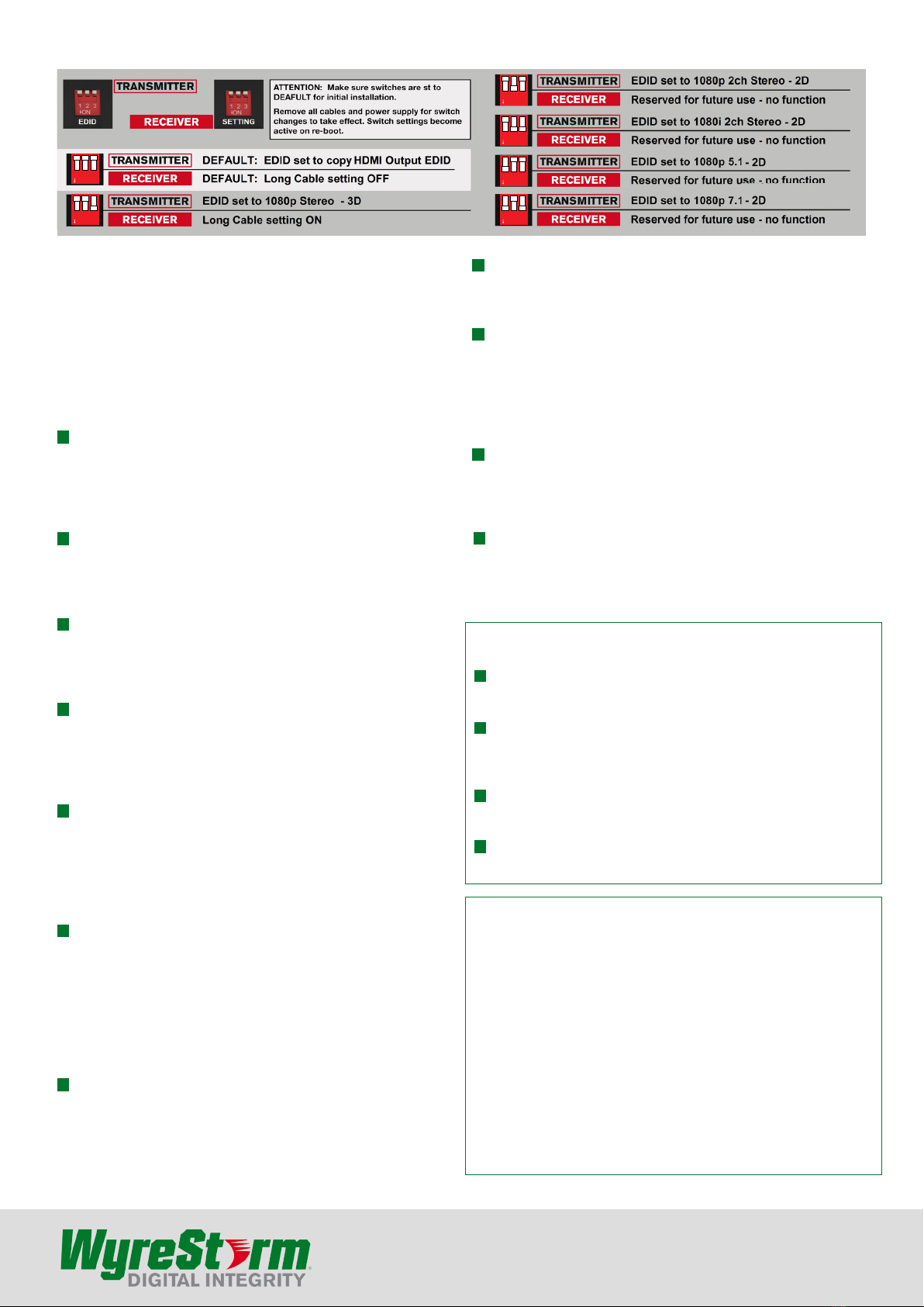
TRANSMITTER EDID & RECEIVER Setting Adjustment
1 2 3
ON
1 2 3
ON
123
ON
123
ON
123
ON
123
ON
For technical support, please call:
US: 901 384 3575
RoW: +44 (0) 1793 230343
Email: [email protected]

Other Wyrestorm Extender manuals

Wyrestorm EX-1UTP-IR-50 User manual

Wyrestorm

Wyrestorm EX-1UTP-IR-50 User manual

Wyrestorm EX-70-G2 Series User manual

Wyrestorm

Wyrestorm EX-70-G2 Series User manual

Wyrestorm EX-SW-0301-H2 User manual

Wyrestorm

Wyrestorm EX-SW-0301-H2 User manual

Wyrestorm EX-35-4K User manual

Wyrestorm

Wyrestorm EX-35-4K User manual

Wyrestorm EX-70-4K-ARC Quickstart Guide User manual

Wyrestorm

Wyrestorm EX-70-4K-ARC Quickstart Guide User manual

Wyrestorm EX-100-4K-PRO User manual

Wyrestorm

Wyrestorm EX-100-4K-PRO User manual

Wyrestorm eX-70-4K User manual

Wyrestorm

Wyrestorm eX-70-4K User manual

Wyrestorm EX-70-H2X User manual

Wyrestorm

Wyrestorm EX-70-H2X User manual

Wyrestorm EXP-EX-COAX-50 User manual

Wyrestorm

Wyrestorm EXP-EX-COAX-50 User manual

Wyrestorm HDBT EX-1UTP-IR-100 User manual

Wyrestorm

Wyrestorm HDBT EX-1UTP-IR-100 User manual

Wyrestorm EXP-EX-COAX-50 User manual

Wyrestorm

Wyrestorm EXP-EX-COAX-50 User manual

Wyrestorm EX-35-H2 User manual

Wyrestorm

Wyrestorm EX-35-H2 User manual

Wyrestorm EX-1UTP-IR-40 User manual

Wyrestorm

Wyrestorm EX-1UTP-IR-40 User manual

Wyrestorm EX-SW-0401-H2-PRO User manual

Wyrestorm

Wyrestorm EX-SW-0401-H2-PRO User manual

Wyrestorm EX-100-H2 User manual

Wyrestorm

Wyrestorm EX-100-H2 User manual

Wyrestorm EX-1UTP-IR-100-EDID User manual

Wyrestorm

Wyrestorm EX-1UTP-IR-100-EDID User manual

Wyrestorm EX-35-H2-ARC User manual

Wyrestorm

Wyrestorm EX-35-H2-ARC User manual

Wyrestorm EX-SW-0201-4K User manual

Wyrestorm

Wyrestorm EX-SW-0201-4K User manual

Wyrestorm EX-70-H2 User manual

Wyrestorm

Wyrestorm EX-70-H2 User manual

Wyrestorm ex-1utp-ir-70-AMP User manual

Wyrestorm

Wyrestorm ex-1utp-ir-70-AMP User manual

Wyrestorm EX-35-4K User manual

Wyrestorm

Wyrestorm EX-35-4K User manual

Wyrestorm EX-40-G2 User manual

Wyrestorm

Wyrestorm EX-40-G2 User manual

Wyrestorm Express exp-EX-HDBT-50 Operating and maintenance instructions

Wyrestorm

Wyrestorm Express exp-EX-HDBT-50 Operating and maintenance instructions

Wyrestorm EXP-EX-80-KVM User manual

Wyrestorm

Wyrestorm EXP-EX-80-KVM User manual

Popular Extender manuals by other brands

Scion-Tech SC08.9000 user manual

Scion-Tech

Scion-Tech SC08.9000 user manual

DPS Telecom NetGuardian E16 DX G2 user manual

DPS Telecom

DPS Telecom NetGuardian E16 DX G2 user manual

E3Switch DS3 Operating information

E3Switch

E3Switch DS3 Operating information

TP-Link RE505X Quick installation guide

TP-Link

TP-Link RE505X Quick installation guide

Appsys ProAudio ADX-32B user manual

Appsys ProAudio

Appsys ProAudio ADX-32B user manual

nedis VREP3460AT quick start guide

nedis

nedis VREP3460AT quick start guide

MuxLab 500464-V2 installation guide

MuxLab

MuxLab 500464-V2 installation guide

on networks N300RE user manual

on networks

on networks N300RE user manual

Hunter Hydrawise HC-1200M quick start guide

Hunter

Hunter Hydrawise HC-1200M quick start guide

Digitus DS-55309 manual

Digitus

Digitus DS-55309 manual

Gefen EXT-VGA-141LR user manual

Gefen

Gefen EXT-VGA-141LR user manual

Lindy 38398 user manual

Lindy

Lindy 38398 user manual

Manhattan IDATA EXT-E504KM instructions

Manhattan

Manhattan IDATA EXT-E504KM instructions

NETVIO EX-HT2-701-10 quick start guide

NETVIO

NETVIO EX-HT2-701-10 quick start guide

ADDER AdderLink X-DVI Guide

ADDER

ADDER AdderLink X-DVI Guide

Siemens PAD-4 Installation, operation and maintenance manual

Siemens

Siemens PAD-4 Installation, operation and maintenance manual

AV Access HDEX40-L user manual

AV Access

AV Access HDEX40-L user manual

CYP CH-1529TXPL Operation manual

CYP

CYP CH-1529TXPL Operation manual

manuals.online logo
manuals.online logoBrands
  • About & Mission
  • Contact us
  • Privacy Policy
  • Terms and Conditions

Copyright 2025 Manuals.Online. All Rights Reserved.